Electronics Production
Introduction
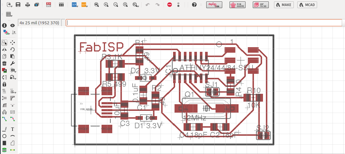
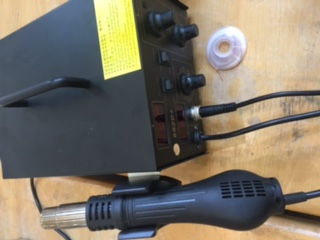
the task for this week is to build Milled circuit board. For this task I have downloaded eagle cad from Autodesk and reviewed basic tutorials on how to start using the application. Additional libraries can be downloaded for free from for example GITHUB.com. Download the library files. Copy the downloaded file into lib folder of eagle CAD. And open & use from within the application. Use schematic drawing and add all the required elements. After connecting them with lines. Convert to PCB drawing. There are two types of elements fixing which are Dip and surface mount. In the lap we will be using surface mount technique. Moreover, I have been introduced tp multimeter, Fulx, heaters, Air Vacuem.
Milling Circuit Board
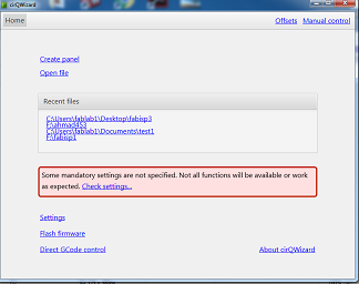
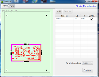
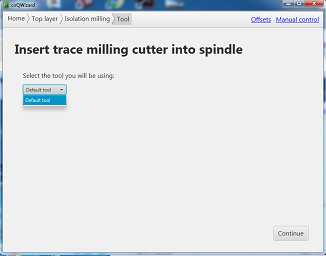
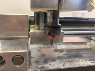
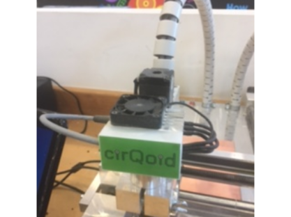
After preparing the BCP file we use the CirQuid Milling Machine LINK HERE CirQuid Milling Machine details .opening the BCP file with its installed software. We open Cirwizard application and the following screen shots demonstrate the Process of milling step by step:
1- Opening and adjusting the file location:
2- Milling the traces on the circuit board:
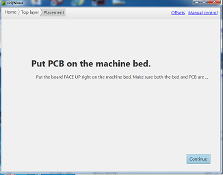
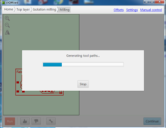
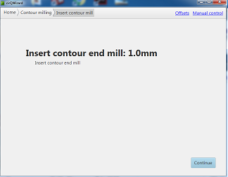
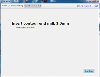
2- Cutting the boarder of the circuit board:
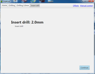
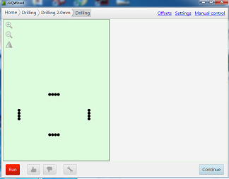
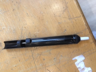
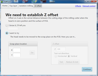
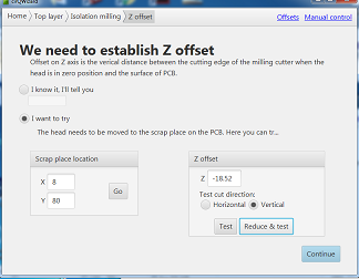
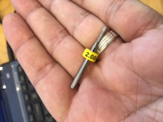
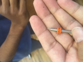
At the begging of miling the circuit I fix the pin of 20.50 mm, after milling the circuit board I changed the pin to 2.00 mm. It cut holes on the boarder of the design on each side to insure during cutting that the board will not get tilted and keeping in mind during all procedures that depth of cutting is well measured. then it cut the whole boarder.
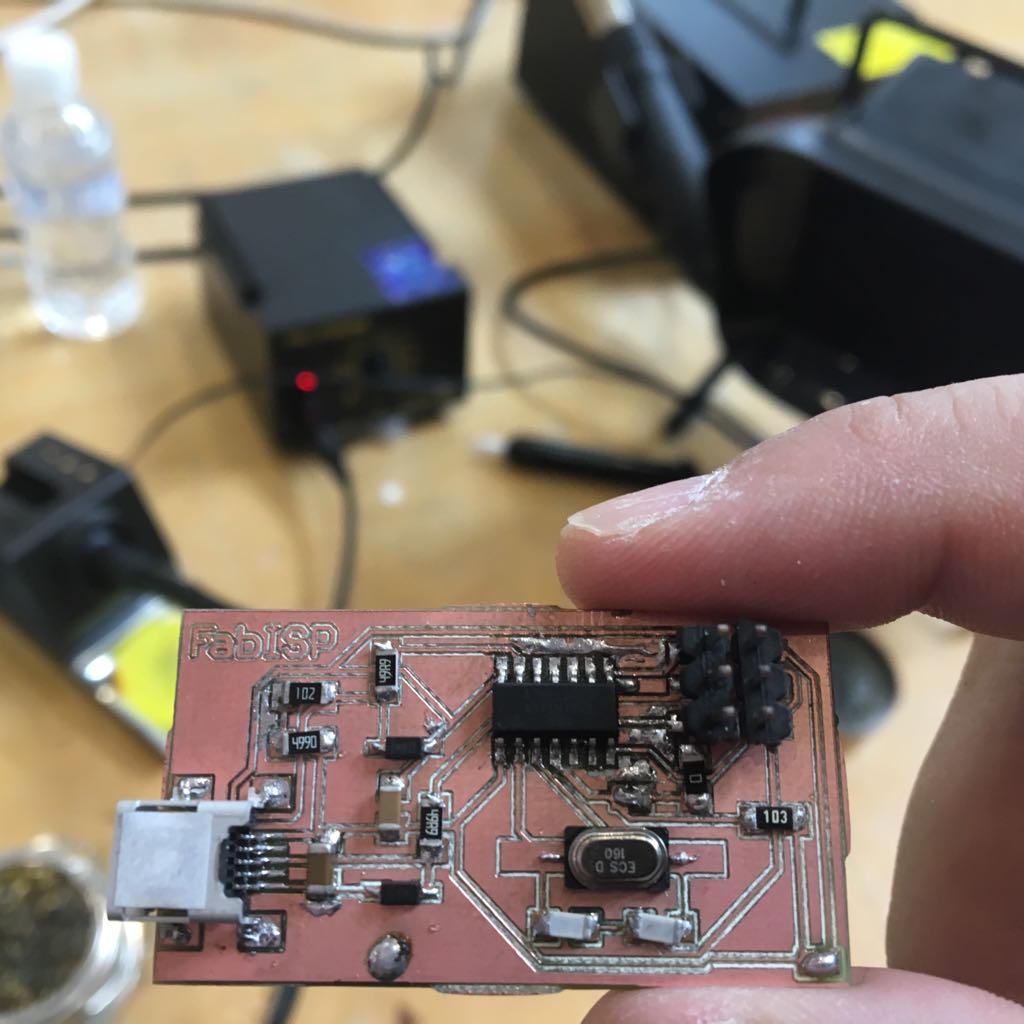
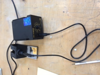
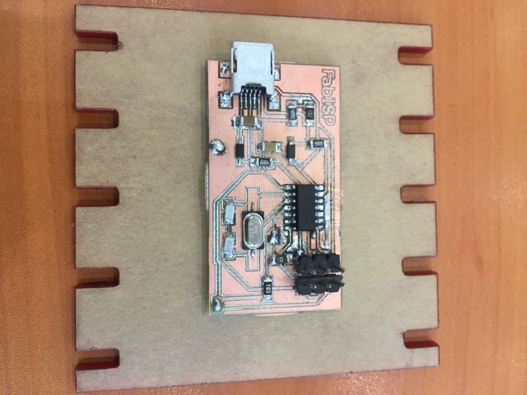
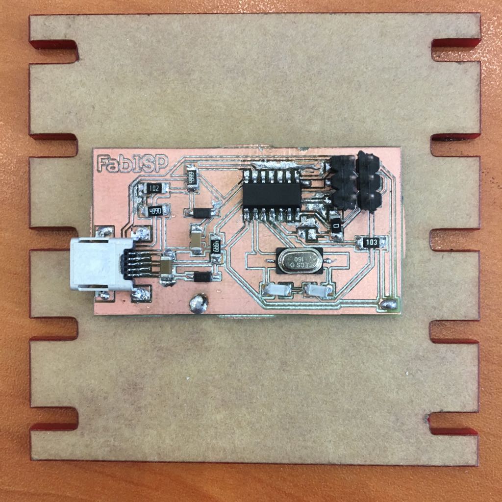
Soldering Board Elemnts
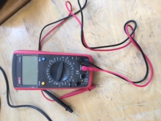
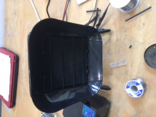
First of all I got familiar with the devices around the work shop. Then I started soldering the Attiny44 element and unfortunately I ruined the soldering by creating short circuit. I milled new circuit board and and start soldering the elements. Whenever I think my soldering is creating a short circuit I check by multimeter and continue Soldering other elements. Connecting the USB seemed an impossible mission. So the instructor advised me to rub flux before soldering the USB and that worked like a wonder.
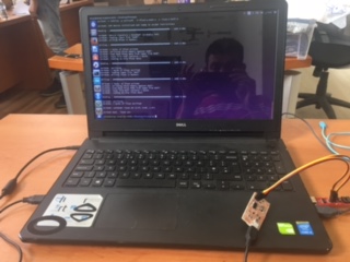
Programming the Circuit Board
After finishing the Soldering and before doing the programing. I had tested if the Circuit Board is connected properly. I googled Attiny44 Diagram and 2x3 Header Diagram and using the Multimeter I have confirmed that I have connected Ground with Ground, Vcc with Vcc … etc. Not to mention that after the check i had to remove the soldering as showmn in the images above.
To install the program have first downloaded some libraries on my PC as shown below:
sudo apt-get install flex byacc bison gcc libusb-dev avrdude
sudo apt-get install gcc-avr
sudo apt-get install avr-libc
sudo apt-get install libc6-dev
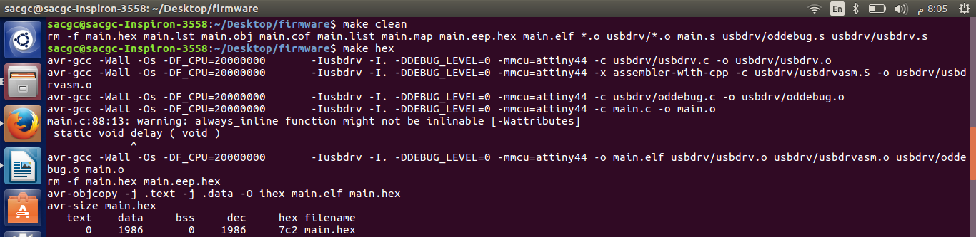
Then we get the Firmware and inside Firmware file are: a file developed in C-Langauge, Makefile in addition to other files.
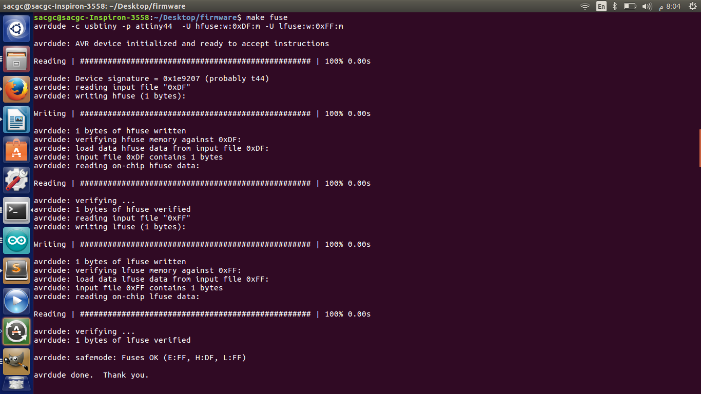
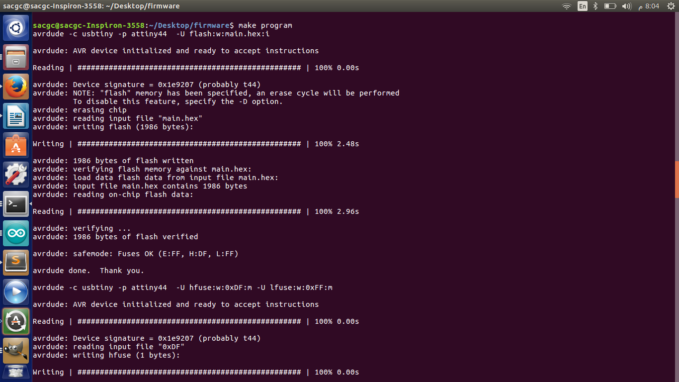
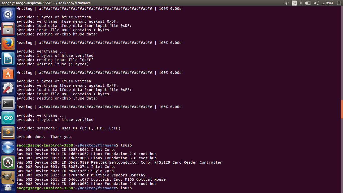
We Type Sudo Make clean to remove Hex files and other already created files. then we Type Sudo Make Hex to change the C-Language format into a hex format lines. then Sudo Make fuse and Sudo make Programe to download the program into my Cicuit Board.
Program Code:
make clean
make hex
make fuse
make program
if it all are ok then we will get a successful message.
Workflow and Area of improvement
The following is the workflow of making a circuit and by following them you will improve the outcome board:
1- Design the Schematic in eagle CAD.
2- Design the BRD file.
a- Add the elments.
b- Apply Design Rules.
c- Do Manual or Automatic Routing.
d- Avoid multible lines passing under the elements As much as possible.
e- After getting 100%, Increase the width of the lines specially VCC and GND.
f- Generate .CMP file for milling.
3- Mill and cut the board using milling machine.
4- Make Sure the copper path is NOT very then to avoid getting burned during testing the board.
5- Solder the elements.
a- Apply flux on the led then solder on the board.
b- Avoid merging the led with other copper lines.
c- Consider the direction of the elements before soldeing such as LED, Attiny ... etc.
6- Make sure of the order of connection for the 2X3 Pins to avoid burining the Attiny.
Download Files
fabisp.sch
fabisp.brd