Embedded Programming
Tasks:
Read a microcontroller data sheet
Program your board to do something, with as many different programming languages and programming environments as possible.
Optionally, experiment with other architectures
After I finished soldering my board, I had to program it. In order to save time, and just make sure that the board is working, I decided to take the short way and program it using the  .
.
To use the Arduino board, I had to patch it in advance adding the Attiny44, detailed instructions can be found HERE. After I patched the Arduino IDE, I connect my arduino board to the USB hub, in the tools menu select the right board (Arduino Uno/Genuino) and the port, after go to File--> examplesand open the Arduino as ISP sketch. Upload the code.
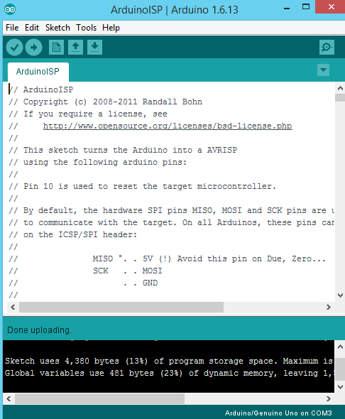
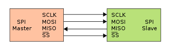
After I see done uploading, which means that the code is uploaded to the board, I disconnect the arduino from the PC. The next step is to connect my PCB board to Arduino using some wires. The connection scheme is this one:
- SCLK: Serial Clock (output from master).
- MOSI: Master Output Slave Input, or Master Out Slave In (data output from master).
- MISO: Master Input Slave Output, or Master In Slave Out (data output from slave).
- VCC: Positive supply voltage.
- GND: Ground.
- RST: Reset.
The right connection is very important, otherwise it is possible to damage the board. That is why, after I triple check the connections, I can go on setting the parameters for the Arduino IDE. I connect the arduino board to the USB hub, and select the right board/processor/frequency -> ATtiny24/44/84, ATtiny44, internal 20Mhz. Under Tools select Arduino as ISP programmer, double check the parameters, and press the Burn Bootloader button.

After everything is done, we can upload any code to our PCB board. I chose a simple example code Blink. It will make the LED blink for 3sec, switch it off for 3sec, and then switch on again, and so on for ever :D. The important thing is to choose the right pin, in my case Pin 7.

Here is a short video:
Ok, now when I am sure that the board is working, we can go deeper into the interesting stuff :p
First thing to do is better understand the microprocessor that I am going to use, ATtiny44 in my case. Honestly, I tried to read the datasheet, but this was so f*king boring. The useful thing which I took from it was the PinOut

After I actually forced myself to finish reading the datasheet, I came up with the conclusion that in order to properly parse the information in a sheet like this is drop everything and take four years of electric engineering, or have someone sit next to you to help you parse the information. These sheets are not consumer facing, they are meant only for experts in the field. In the meanwhile, there are plenty of other sources through Google search that yield the information needed that does not require the parsing of a datasheet such as this.

For this assignment, I decided to use my FabISP board which I made in the previous weeks to program my HelloBoard!
On the FabISP and HelloBoard I have all the necessary pins for the AVR connection, so I just connect them (VCC of the FabISP to VCC of the HelloBoard, MOSI to MOSI, MISO to MISO, GND to GND, RST to RST, and the SCK to the SCK accordingly)
After I connected the FabISP to my HelloBoard, I have to install the necessary software for AVR Programming. Because I use Ubuntu, I just have to follow the steps:
Get and install avrdude / GCC software and dependencies:
Open Terminal and type:
sudo apt-get install flex byacc bison gcc libusb-dev avrdude
Then type:
sudo apt-get install gcc-avr
- type "y" when asked to do so by your system
Then type:
sudo apt-get install avr-libc
Then type (may already be installed):
sudo apt-get install libc6-dev
So basically, I will need just three things to program my board:
- The necessary libraries (AVR, avr-gcc and avrdude)
- The Make and makefiles
- And the actual .c code which I want to upload
Since we normally use AVR microcontrollers in the Fab Academy, we need to write a C code for them, compile it with avr-gcc and send it to the microcontroller with avrdude. When you need to deal with multiple configurations and commands when compiling a software, you can use the make command on Mac/Linux for automatizing this task.
make reads automatically a Makefile file in the folder where you launch it (it should be the folder where your project can be found). Following the Fab Academy Turorial, I had to write my own MakeFile. I took the Neil's example from HERE and modified it for myself. The initial file had a general purpose, so I deleted all the unnecessary code lines, changed the name of the project,and changed the name of the commands.
Now it looks like this:
PROJECT=blink
SOURCES=$(PROJECT).c
MMCU=attiny44
F_CPU = 20000000

CFLAGS=-mmcu=$(MMCU) -Wall -Os -DF_CPU=$(F_CPU)

$(PROJECT).hex: $(PROJECT).out
	avr-objcopy -O ihex $(PROJECT).out $(PROJECT).c.hex;\
	avr-size --mcu=$(MMCU) --format=avr $(PROJECT).out

$(PROJECT).out: $(SOURCES)
	avr-gcc $(CFLAGS) -I./ -o $(PROJECT).out $(SOURCES)


program-fabISP: $(PROJECT).hex
	avrdude -p t44 -P usb -c usbtiny -U flash:w:$(PROJECT).c.hex
So I downloaded the AVR libraries, I have my MakeFile, the last missing component is the .C code!
Because I am not familiar with the C programming language, I had to spend some time on tutorials) I decided to write a simple code, which will involve two LED's.
Honestly, I was never expecting to use my board :D, so I had only one LED which I could control from a Digital Pin. Even the button that I have, one is for the reset of the board, another one is just a switch for the LED which is connected to the VCC. But luckily, I made one additional digital pin, as I said: Just in case :D and Here it is the right CASE!!!
That is why I will add an external LED on a breadboard, which I will control using my additional Digital Pin
The idea of the C code is to make one LED blink with a certain delay, as simple as that, but the second LED should adjust according to the behaviour of the first one. So, the First LED is ON, the Second LED is OFF, and the other way around, when the First LED is OFF, the Second should be ON. Easy?!, but not really when you program in C for the first time!)
And here is my code:
#include  <avr/io.h>
#include  <util/delay.h>

#define F_CPU20000UL
#define LED_YELLOW_PORT PORTA
#define LED_GREEN_PORT PORTB

int main (void){

  DDRA = 0xFF;  //set PORTA for output
  DDRB = 0xFF;  //set PORTB for output


  while (1){

      LED_YELLOW_PORT = 0b10000000;  //set PORTA.7 high
      switchGreenLED();

      _delay_ms(1000);

      LED_YELLOW_PORT = 0b00000000;  //set PORTA.7 low
      switchGreenLED();

      _delay_ms(1000);
  }
}

 void switchGreenLED() {

   if ( LED_YELLOW_PORT == 0b10000000) {

       LED_GREEN_PORT = 0b00000000;

   }else
   if ( LED_YELLOW_PORT == 0b00000000) {

       LED_GREEN_PORT = 0b00000100;
   }
 }
I tried to use comments, to make clear what the code is doing. In the main funtion, the first LED is blinking with a delay of one second. The switchGreenLED funtion, which is the second LED, is constantly checking the status of the first LED, and reacts accordingly!
Easy shit :D
So I have the AVR libraries, the makefile, and the C code. I am ready to upload it to the microcontroller!
I double check the connections between the FabISP and HelloBoard, and connect the FabISP to the USB hub
I placed the makefile and the C code together in one folder. Then using the bash command, I go to the folder where the files are located, and use the make command together with the programming command which I defined in the makefile, in my case it is make program-fabISP
After the code is compiled, the upload is successful!
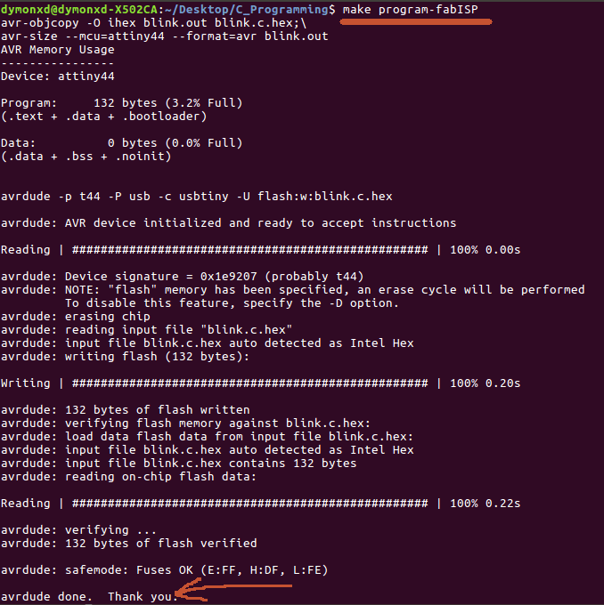
Here is the log of my commands:
dymonxd@dymonxd-X502CA:~/Desktop/C_Programming$ make
avr-objcopy -O ihex blink.out blink.c.hex;\
avr-size --mcu=attiny44 --format=avr blink.out
AVR Memory Usage
----------------
Device: attiny44

Program:     132 bytes (3.2% Full)
(.text + .data + .bootloader)

Data:          0 bytes (0.0% Full)
(.data + .bss + .noinit)


dymonxd@dymonxd-X502CA:~/Desktop/C_Programming$ make program-fabISP
avr-objcopy -O ihex blink.out blink.c.hex;\
avr-size --mcu=attiny44 --format=avr blink.out
AVR Memory Usage
----------------
Device: attiny44

Program:     132 bytes (3.2% Full)
(.text + .data + .bootloader)

Data:          0 bytes (0.0% Full)
(.data + .bss + .noinit)


avrdude -p t44 -P usb -c usbtiny -U flash:w:blink.c.hex

avrdude: AVR device initialized and ready to accept instructions

Reading | ################################################## | 100% 0.00s

avrdude: Device signature = 0x1e9207 (probably t44)
avrdude: NOTE: "flash" memory has been specified, an erase cycle will be performed
         To disable this feature, specify the -D option.
avrdude: erasing chip
avrdude: reading input file "blink.c.hex"
avrdude: input file blink.c.hex auto detected as Intel Hex
avrdude: writing flash (132 bytes):

Writing | ################################################## | 100% 0.20s

avrdude: 132 bytes of flash written
avrdude: verifying flash memory against blink.c.hex:
avrdude: load data flash data from input file blink.c.hex:
avrdude: input file blink.c.hex auto detected as Intel Hex
avrdude: input file blink.c.hex contains 132 bytes
avrdude: reading on-chip flash data:

Reading | ################################################## | 100% 0.22s

avrdude: verifying ...
avrdude: 132 bytes of flash verified

avrdude: safemode: Fuses OK (E:FF, H:DF, L:FE)

avrdude done.  Thank you.

dymonxd@dymonxd-X502CA:~/Desktop/C_Programming$
Here is the proof video :D
Now let's make something else! I cannot say that there are many options of what you can do with the Hello Board, but I wanted to use an input device as well. Because the buttons on my board have no use, and I cannot control it digitaly, I have to add an external button, which I placed on the bread board. I used the following wiring schematics:
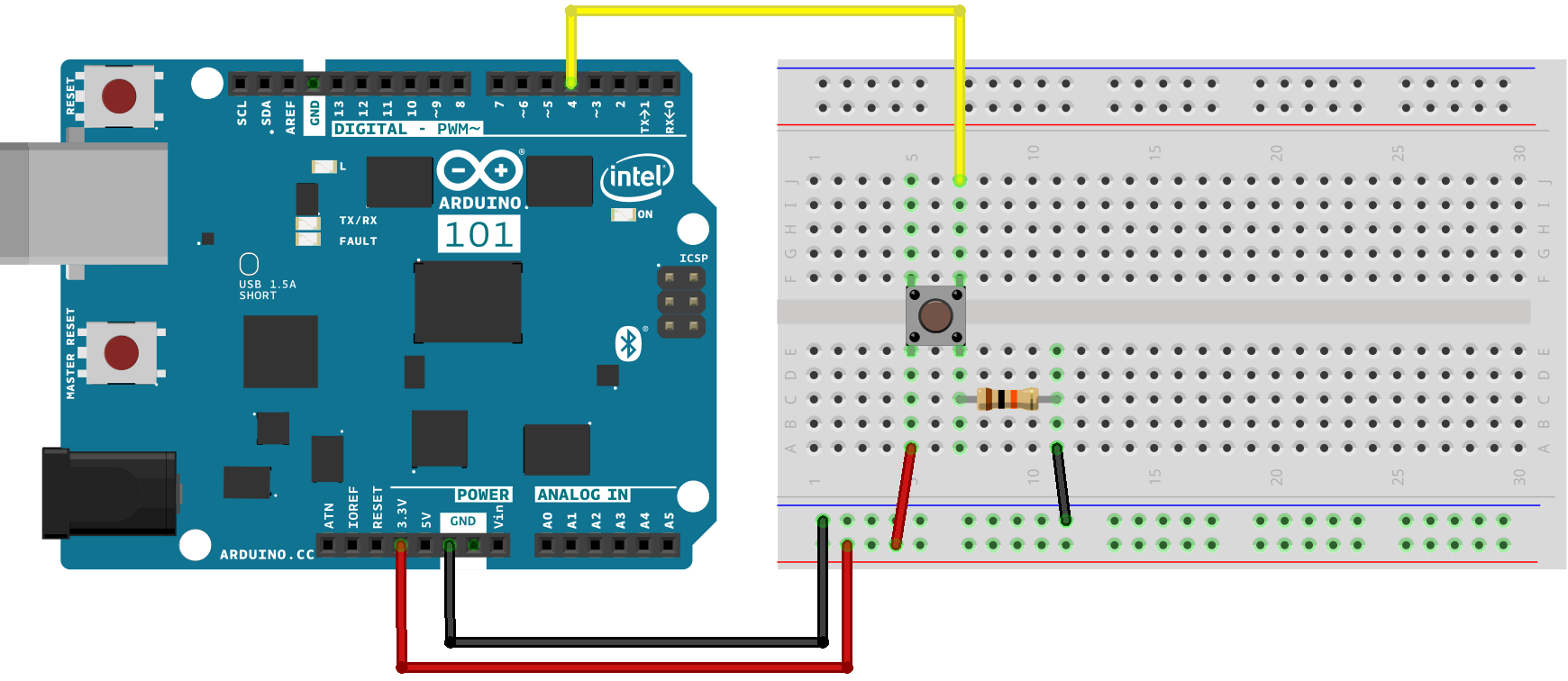
And let's write the code! The idea is that when I press the button, the LED will switch on, when I press second time, the LED is off. Here is how I implemented it:
#include  <avr/io.h>
#include  <util/delay.h>

int Button_Pressed();
int pressed;
int state ;

void init() {

 DDRB = 0b00000000; //Makes PORTB as Input
 DDRA = 0b11111111; //Makes PORTA as Output
 PORTA= 0b00000000; //Turns OFF All Outputs
 state=0;
}
int Button_Pressed(){

  /* the button is pressed*/
  if (bit_is_set(PINB, PB2)){

    //wait a certain time for button debounce
    _delay_ms(5); //5 milli second delay

     if (bit_is_set(PINB, PB2)){

      return 1;

  }}

  return 0;

}
int main(void)
{
    init();

  while(1) //infinite loop
  {
pressed=Button_Pressed();

  if(pressed&&state==0){PORTA = 0b10000000; //Turns ON LED In my case it's Pin Number 7
    _delay_ms(500); //0.5 second delay
    pressed=0;
    state=1;
  }
   if(pressed&&state==1){    PORTA= 0b00000000; //Turns OFF All LED
    _delay_ms(500); //0.5 second delay
    pressed=0;
    state=0;
  }

  }

  }
Here is the video:
Download Files: