Electronics Production
Tasks:
Make an in-circuit programmer by milling the PCB
Optionally, trying other processes.
Finally we are approaching the most exciting in my opinion topic Electronics. This week I will create my first PCB circuit board.
PCB stands for Printed Circuit Board and is a good solutions for mounting/assembling/soldering our electronic components together. So the board is something solid covered with a thin sheet of copper that we etch or mill (or other process), leaving just the path where we want to conduce electrons to our electronic components.
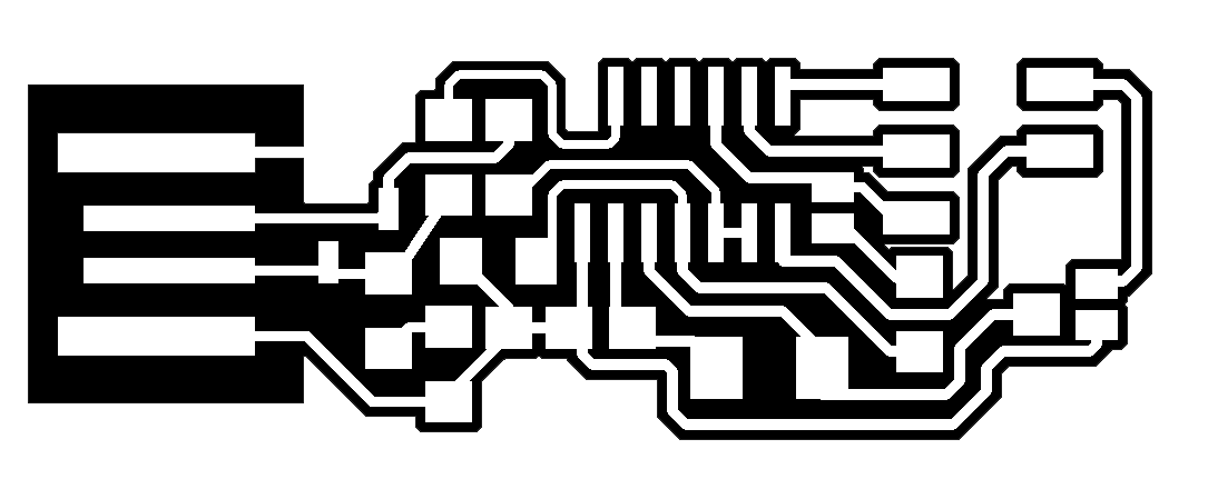
I started the construction of my board by using the Roland MDX-40A milling machine, to create the path. In order to do so, we used some already designed models. We had 2 .PNG files from the already existing design, one is the outline (I call it a frame) that is the cut out frame, and the other file represents the traces which are the paths inside.
We used FabModules to convert the .PNG files into Gcodes for the Roland machine. Fab Modules is a Computer-Aided-Manufacturing (CAM) software developed as an web application, which can operate several FabLab machines. It is released as custom MIT-like license on the Fab Modules github repository and it is currently being actively developed from the Fab Academy and FabLabs.
The MDX-40A machine, which is available for us, seems to not be supported directly by the Fab Modules, yet instead there is support for similar machines such as the MDX-40 and the SRM20. The MDX-40A doesn’t support the serial connection but only the parallel, so it requires a similar driver of the SRM20, that is another machine that supports only the parallel connection. So what we had to do is connect to the FabLab Wi-Fi network, open the browser, and go to the ip adress indicated in the server.
Before using the Fab Modules, we had to be sure that the machine is connected to the Fab Modules computer near the MDX-40A.
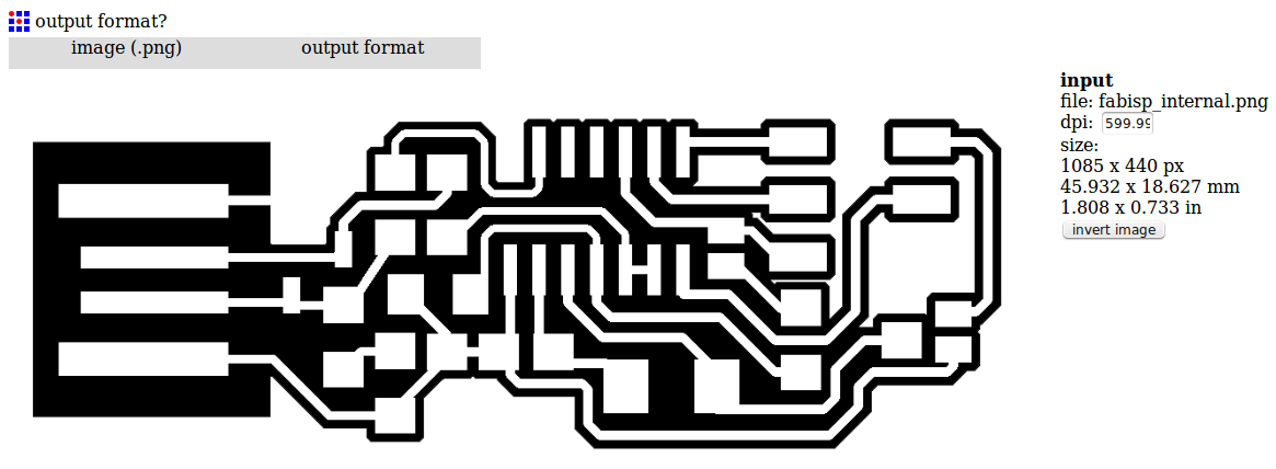
Let’s start to work with the Fab Modules. When I introduce the ip adress into the browser window, the first interface that will appear is:

After I press on th gray button input format, a new menu should appear with the option to load the .PNG image. Here I upload the first image, which is the inside engraving. After doing that, the preview of the image will appear in the Fab Modules and also other fields and other parameters will show up:
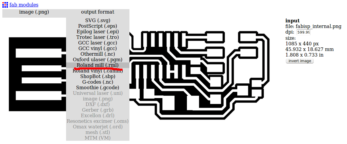
Now you have to choose the output format, that will be the Roland mill (.rml)
And finally as process I choose PCB traces (1/64). Is possible to use exactly the same process for making the outline cut of the board and making the holes.
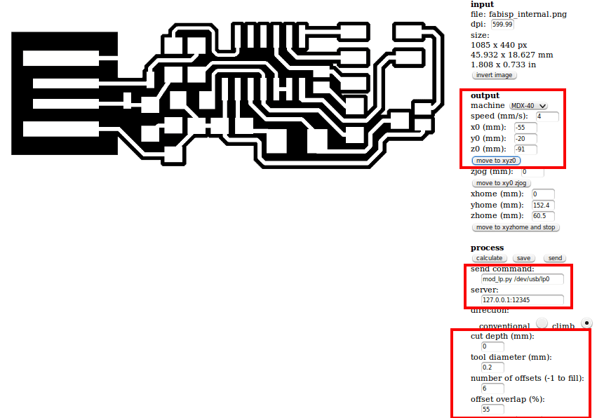
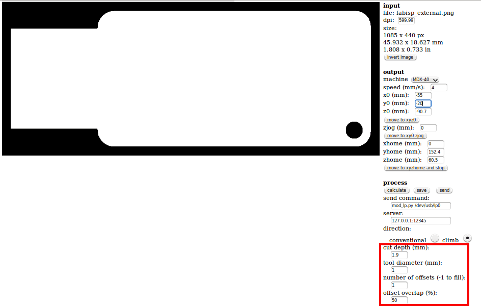
Now let's set the parameters for the Roland machine. On the right side of the window, we have many input parameters. In order to be able to move the machine, we have to input the following parameters:

mod_lp.py /dev/usb/lp0 into the send command field
hostname_of_your_machine into the server field (just the address without http or /)
In order to move the machine I just enter in the respective fields the x, y and z position coordinates. Before moving the machine I have to make sure that the zjog parameter is always set to 0, even if it will change automatically. To move the machine I have to press the move to xyz0 button.
The hard thing to do was to adjust the x0 y0 z0 for the machine, took me a while :) After I found the right coordinates, I had to make sure that the tool is actually touching the copper surface.
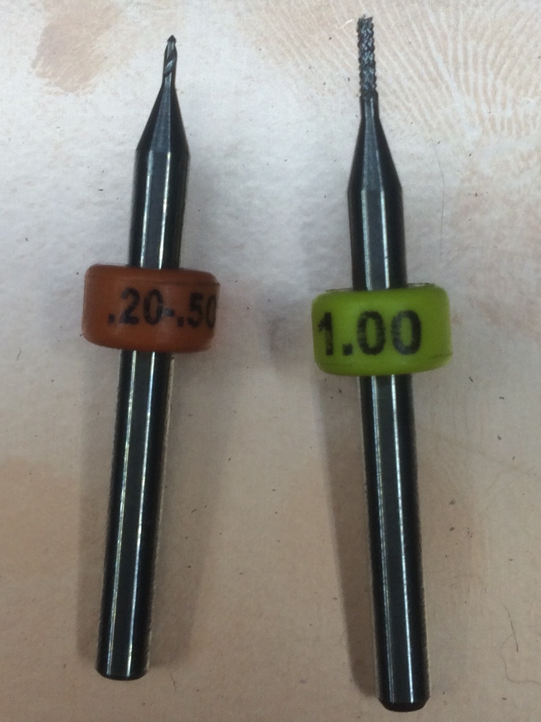
* A small life hack is to use the multimeter and check if there is connection between the tool and the surface. As a tool to engrave PCB is suggested to use diameter from 0.2 mm and below, while for cutting we can use a 1 mm tool.
So my final settings look like this:
After I double check all the settings, I press the calculate button. This is what I get:

On this picture we can see all the paths and the jumps that the machine will do. Now I am ready to send the job to the MDX-40A by pressing the send button.
For the outside cut the settings remain the same with the exception of the value of the Z-Axis, as I replaced the 0.2mm tool with the 1mm tool, and the parameters of the CAM. This is how it looks:
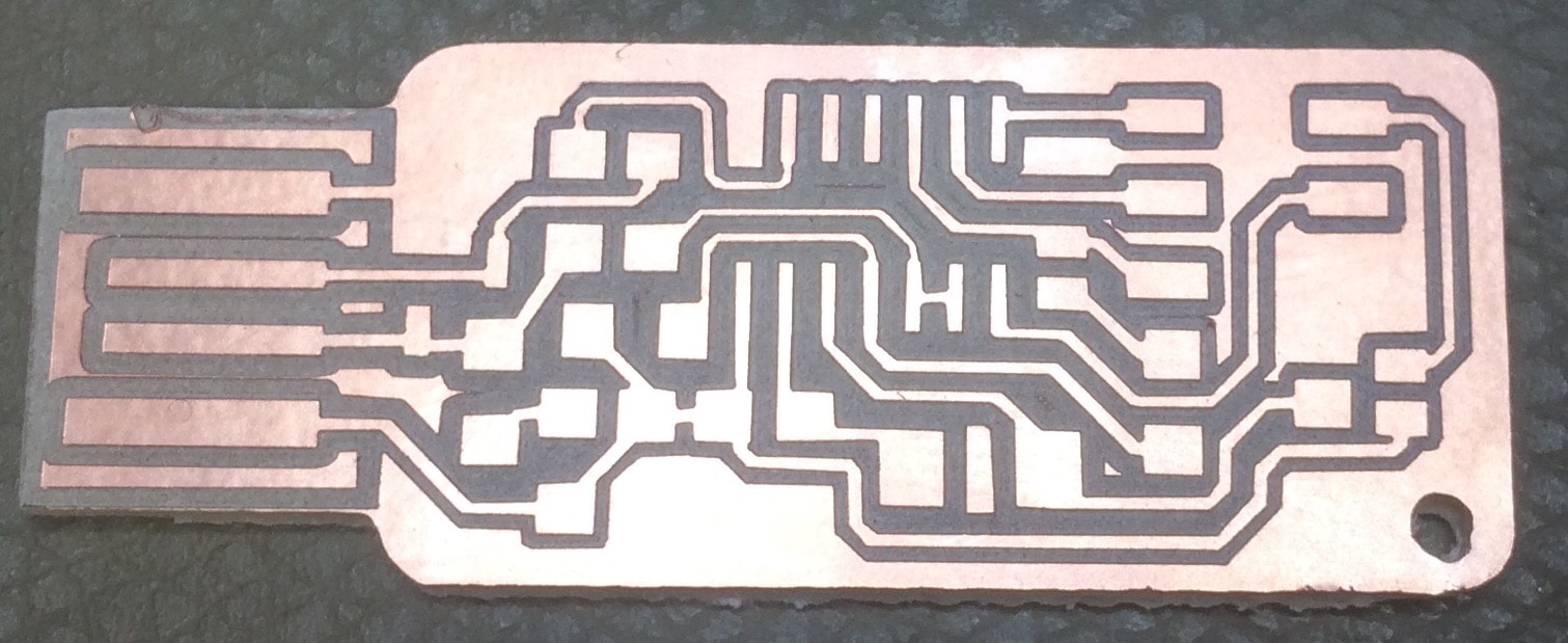
The first job, the inside engraving, took about 20 min, but the result was really good. Analyzing the draft circuit, the result proves that the parameters chosen in the CAM software were the right ones.
After the inside engraving was finished, I was ready to launch the second job, which is the outside cut. I changed the tool from 0.2mm to 1mm, fixed the new z0 position, and set the right parameters. Because copper is a strong material, and the tool diameter is only 1mm, I had to decrease the speed dramaticly, from 4mm/s to 0.5mm/s, which as a result took more time to cut. This is how the final result of both cuts looks:
And now comes the HARDCORE! Time to solder all the components on my PCB board. Because it was not my first experience in soldering, it did not take me much time. The components that I used are:
- 1 ATTiny 44 microcontroller
- 1 Capacitor 1uF
- 0.1 Capacitor 1uF
- 2 Capacitor 10 pF
- 2 Resistor 100 ohm
- 1 Resistor 499 ohm
- 1 Resistor 1K ohm
- 1 Resistor 10K
- one 6 pin header
- 1 Cystal 20MHz
In order to make sure that I soldered everything in a right way, after each component soldered, I used the multimeter to check if there is conductivity between the component and the traces. Honestly saying, the begining was hell, but at the end I really liked soldering :)
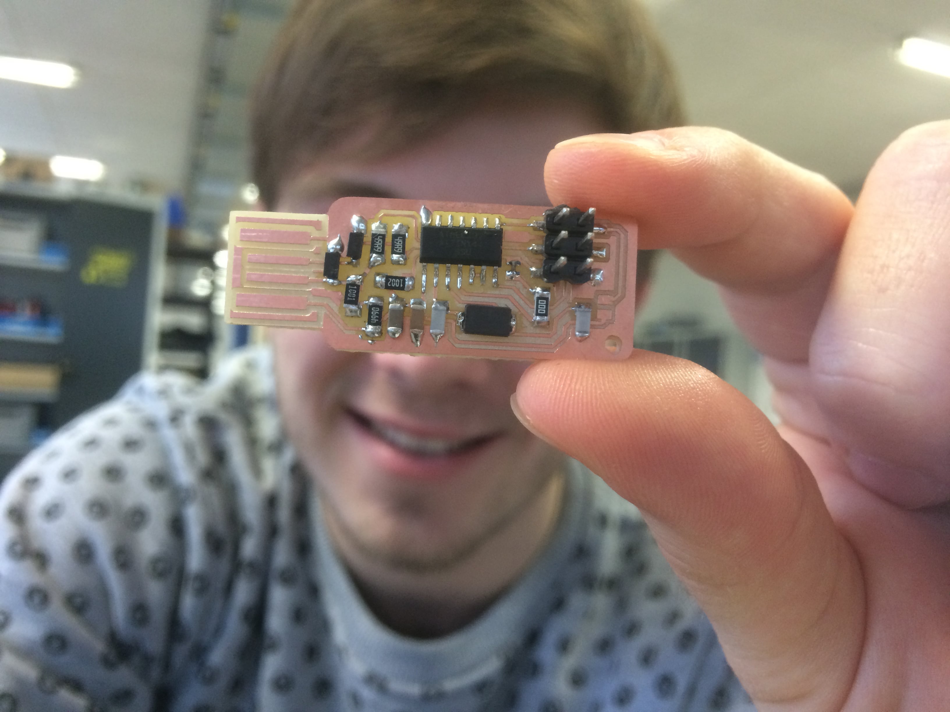
My PCB with all the components on it looks like this:
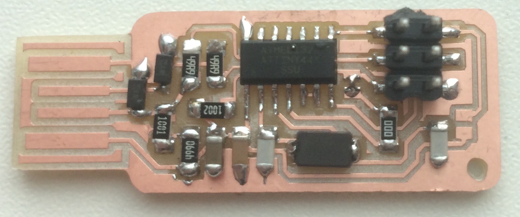
Just look at this. Isn't it beautiful? :D
The next step is to Program It! Now I have only a board with some components on it, but let's give it LIFE. The software wich I am using is  , an open source software which allows to program newly created boards. And yes, in order to program a board we have to use another board; its like Egg / Chicken situation - what appeared first :D
In-system programming (ISP) is the ability of some programmable logic devices, microcontrollers, and other embedded devices to be programmed while installed in a complete system, rather than requiring the chip to be programmed prior to installing it into the system. This may allow manufacturers to program the chips in their own system's production line instead of buying pre-programmed chips from a manufacturer or distributor, making it feasible to apply code or design changes in the middle of production run.

First, I have to install the necessary software for AVR Programming. Because I use Ubuntu, I just have to follow the steps:
Get and install avrdude / GCC software and dependencies:
Open Terminal and type:
sudo apt-get install flex byacc bison gcc libusb-dev avrdudeThen type:
sudo apt-get install gcc-avr- type "y" when asked to do so by your system
Then type:
sudo apt-get install avr-libcThen type (may already be installed):
sudo apt-get install libc6-dev
Download and Unzip the Firmware:
Move to the desktop
cd ~/Desktop Download the firmware from the Fab Academy Electronics Production page.
wget http://academy.cba.mit.edu/classes/embedded_programming/firmware.zip Unzip the firmware
unzip firmware.zip Now, I connect an Arduino UNO to my computer, open the Arduino IDE, and select the proper Port and Board from the Tools menu.
ArduinoISP, and press Upload sketch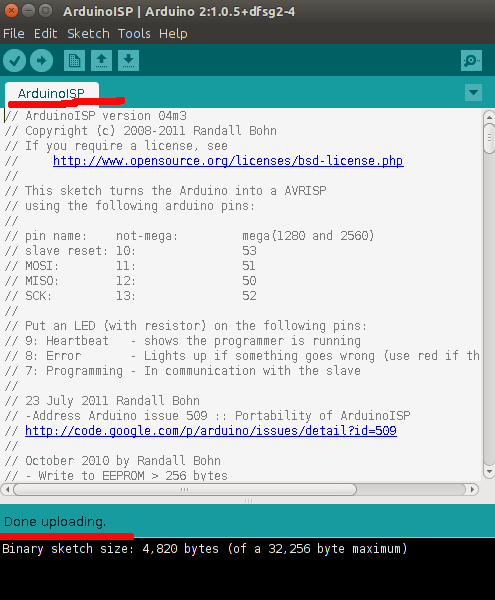
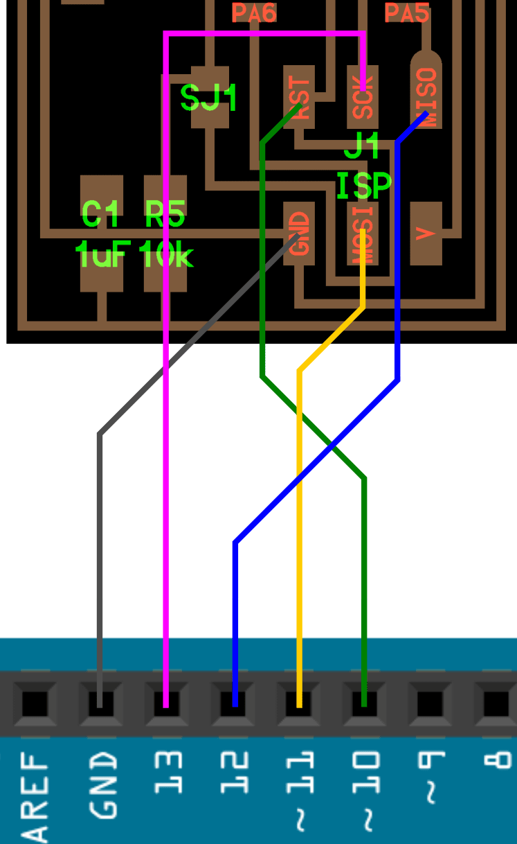
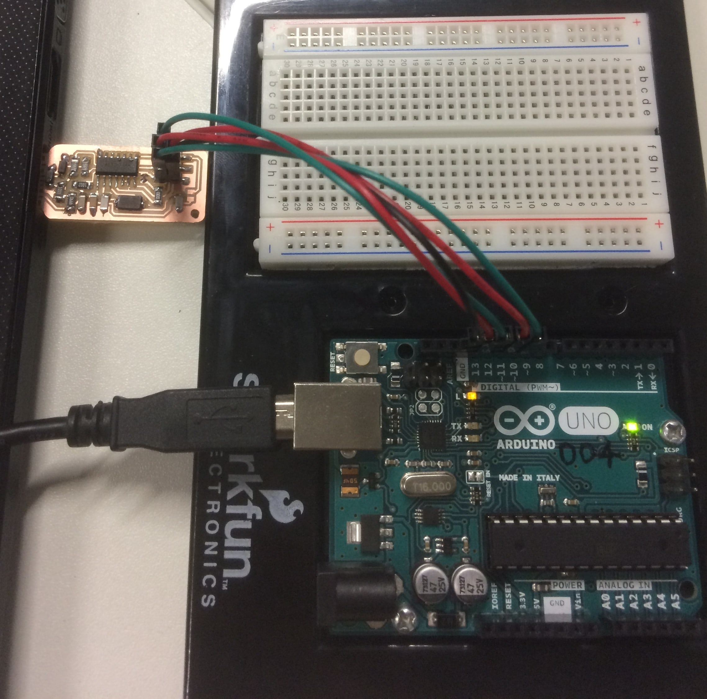
Then I can connect the Arduino to the FabISP as shown below:
After I double checked the connections, I connect the Arduino to my computer and place the FabISP into the USB port.
Using the command line, I go to the unziped firmware folder. After I do this, I type the following commands:
make cleanThen type:
make hexAfter I do these steps, I open the MakeFile with a text editor and change this line:
AVRDUDE = avrdude -c avrisp2 -P usb -p $(DEVICE), to this one AVRDUDE = avrdude -c stk500v1 -P /dev/ttyACM0 -b19200 -p $(DEVICE).
I save the file, and do the following commands:
make fuseAnd then:
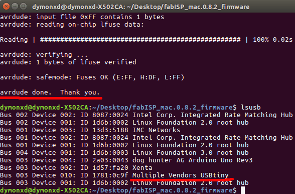
make programFinally, If i enter lsusb command, I should see in the list Multiple Vendors USB
Here is my hystory of commands:
dymonxd@dymonxd-X502CA:~/Desktop/fabISP_mac.0.8.2_firmware$ make clean
rm -f main.hex main.lst main.obj main.cof main.list main.map main.eep.hex main.elf *.o usbdrv/*.o main.s usbdrv/oddebug.s usbdrv/usbdrv.s
dymonxd@dymonxd-X502CA:~/Desktop/fabISP_mac.0.8.2_firmware$ make hex
avr-gcc -Wall -Os -DF_CPU=20000000	 -Iusbdrv -I. -DDEBUG_LEVEL=0 -mmcu=attiny44 -c usbdrv/usbdrv.c -o usbdrv/usbdrv.o
avr-gcc -Wall -Os -DF_CPU=20000000	 -Iusbdrv -I. -DDEBUG_LEVEL=0 -mmcu=attiny44 -x assembler-with-cpp -c usbdrv/usbdrvasm.S -o usbdrv/usbdrvasm.o
avr-gcc -Wall -Os -DF_CPU=20000000	 -Iusbdrv -I. -DDEBUG_LEVEL=0 -mmcu=attiny44 -c usbdrv/oddebug.c -o usbdrv/oddebug.o
avr-gcc -Wall -Os -DF_CPU=20000000	 -Iusbdrv -I. -DDEBUG_LEVEL=0 -mmcu=attiny44 -c main.c -o main.o
main.c:88:13: warning: always_inline function might not be inlinable [-Wattributes]
 static void delay ( void )
             ^
avr-gcc -Wall -Os -DF_CPU=20000000	 -Iusbdrv -I. -DDEBUG_LEVEL=0 -mmcu=attiny44 -o main.elf usbdrv/usbdrv.o usbdrv/usbdrvasm.o usbdrv/oddebug.o main.o
rm -f main.hex main.eep.hex
avr-objcopy -j .text -j .data -O ihex main.elf main.hex
avr-size main.hex
   text	   data	    bss	    dec	    hex	filename
      0	   1986	      0	   1986	    7c2	main.hex
dymonxd@dymonxd-X502CA:~/Desktop/fabISP_mac.0.8.2_firmware$ make fuse
avrdude -c stk500v1 -P /dev/ttyACM0 -b19200 -p attiny44 -U hfuse:w:0xDF:m -U lfuse:w:0xFF:m

avrdude: AVR device initialized and ready to accept instructions

Reading | ################################################## | 100% 0.05s

avrdude: Device signature = 0x1e9207 (probably t44)
avrdude: reading input file "0xDF"
avrdude: writing hfuse (1 bytes):

Writing | ################################################## | 100% 0.02s

avrdude: 1 bytes of hfuse written
avrdude: verifying hfuse memory against 0xDF:
avrdude: load data hfuse data from input file 0xDF:
avrdude: input file 0xDF contains 1 bytes
avrdude: reading on-chip hfuse data:

Reading | ################################################## | 100% 0.02s

avrdude: verifying ...
avrdude: 1 bytes of hfuse verified
avrdude: reading input file "0xFF"
avrdude: writing lfuse (1 bytes):

Writing | ################################################## | 100% 0.06s

avrdude: 1 bytes of lfuse written
avrdude: verifying lfuse memory against 0xFF:
avrdude: load data lfuse data from input file 0xFF:
avrdude: input file 0xFF contains 1 bytes
avrdude: reading on-chip lfuse data:

Reading | ################################################## | 100% 0.02s

avrdude: verifying ...
avrdude: 1 bytes of lfuse verified

avrdude: safemode: Fuses OK (E:FF, H:DF, L:FF)

avrdude done.  Thank you.

dymonxd@dymonxd-X502CA:~/Desktop/fabISP_mac.0.8.2_firmware$ make program
avrdude -c stk500v1 -P /dev/ttyACM0 -b19200 -p attiny44 -U flash:w:main.hex:i

avrdude: AVR device initialized and ready to accept instructions

Reading | ################################################## | 100% 0.05s

avrdude: Device signature = 0x1e9207 (probably t44)
avrdude: NOTE: "flash" memory has been specified, an erase cycle will be performed
         To disable this feature, specify the -D option.
avrdude: erasing chip
avrdude: reading input file "main.hex"
avrdude: writing flash (1986 bytes):

Writing | ################################################## | 100% 3.41s

avrdude: 1986 bytes of flash written
avrdude: verifying flash memory against main.hex:
avrdude: load data flash data from input file main.hex:
avrdude: input file main.hex contains 1986 bytes
avrdude: reading on-chip flash data:

Reading | ################################################## | 100% 2.39s

avrdude: verifying ...
avrdude: 1986 bytes of flash verified

avrdude: safemode: Fuses OK (E:FF, H:DF, L:FF)

avrdude done.  Thank you.

avrdude -c stk500v1 -P /dev/ttyACM0 -b19200 -p attiny44 -U hfuse:w:0xDF:m -U lfuse:w:0xFF:m

avrdude: AVR device initialized and ready to accept instructions

Reading | ################################################## | 100% 0.05s

avrdude: Device signature = 0x1e9207 (probably t44)
avrdude: reading input file "0xDF"
avrdude: writing hfuse (1 bytes):

Writing | ################################################## | 100% 0.02s

avrdude: 1 bytes of hfuse written
avrdude: verifying hfuse memory against 0xDF:
avrdude: load data hfuse data from input file 0xDF:
avrdude: input file 0xDF contains 1 bytes
avrdude: reading on-chip hfuse data:

Reading | ################################################## | 100% 0.02s

avrdude: verifying ...
avrdude: 1 bytes of hfuse verified
avrdude: reading input file "0xFF"
avrdude: writing lfuse (1 bytes):

Writing | ################################################## | 100% 0.02s

avrdude: 1 bytes of lfuse written
avrdude: verifying lfuse memory against 0xFF:
avrdude: load data lfuse data from input file 0xFF:
avrdude: input file 0xFF contains 1 bytes
avrdude: reading on-chip lfuse data:

Reading | ################################################## | 100% 0.02s

avrdude: verifying ...
avrdude: 1 bytes of lfuse verified

avrdude: safemode: Fuses OK (E:FF, H:DF, L:FF)

avrdude done.  Thank you.

dymonxd@dymonxd-X502CA:~/Desktop/fabISP_mac.0.8.2_firmware$ lsusb
Bus 002 Device 002: ID 8087:0024 Intel Corp. Integrated Rate Matching Hub
Bus 002 Device 001: ID 1d6b:0002 Linux Foundation 2.0 root hub
Bus 001 Device 003: ID 13d3:5188 IMC Networks
Bus 001 Device 002: ID 8087:0024 Intel Corp. Integrated Rate Matching Hub
Bus 001 Device 001: ID 1d6b:0002 Linux Foundation 2.0 root hub
Bus 004 Device 001: ID 1d6b:0003 Linux Foundation 3.0 root hub
Bus 003 Device 004: ID 2a03:0043 dog hunter AG Arduino Uno Rev3
Bus 003 Device 002: ID 1d57:fa20 Xenta
Bus 003 Device 010: ID 1781:0c9f Multiple Vendors USBtiny
Bus 003 Device 001: ID 1d6b:0002 Linux Foundation 2.0 root hub
dymonxd@dymonxd-X502CA:~/Desktop/fabISP_mac.0.8.2_firmware$
Download Files:

