INTERFACE AND APPLICATION PROGRAMMING
ASSIGNMENT
Write an application that interfaces with an input &/or output device that you made,
RE-DESIGN OF BOARD
This week I redesigned the stepper motor board, added some pins and improved the layout.
Pictures below show the differences in trace sizes for the jc-watchobot-v1.0 (on the left) and the v2.0 (on the right).
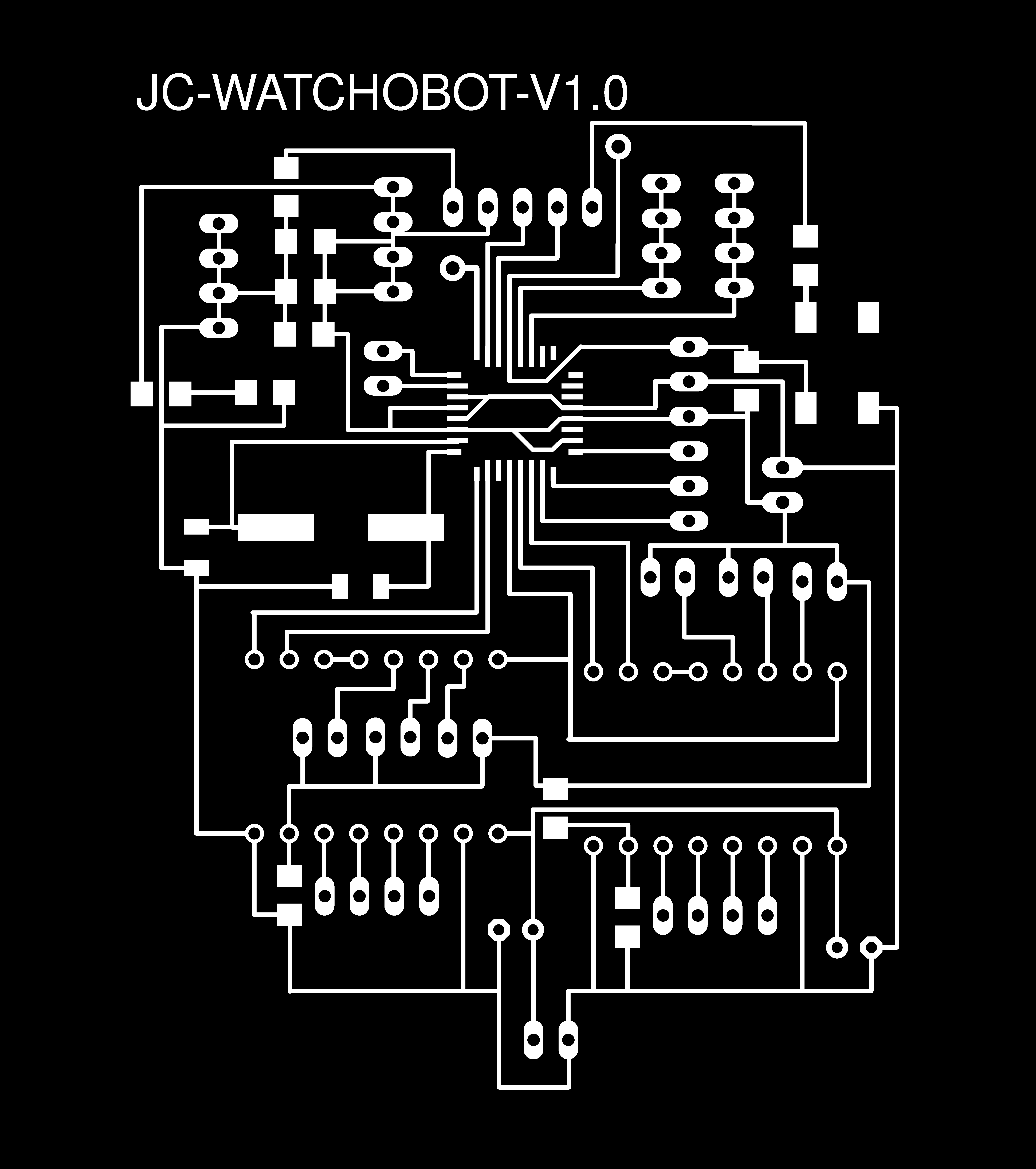
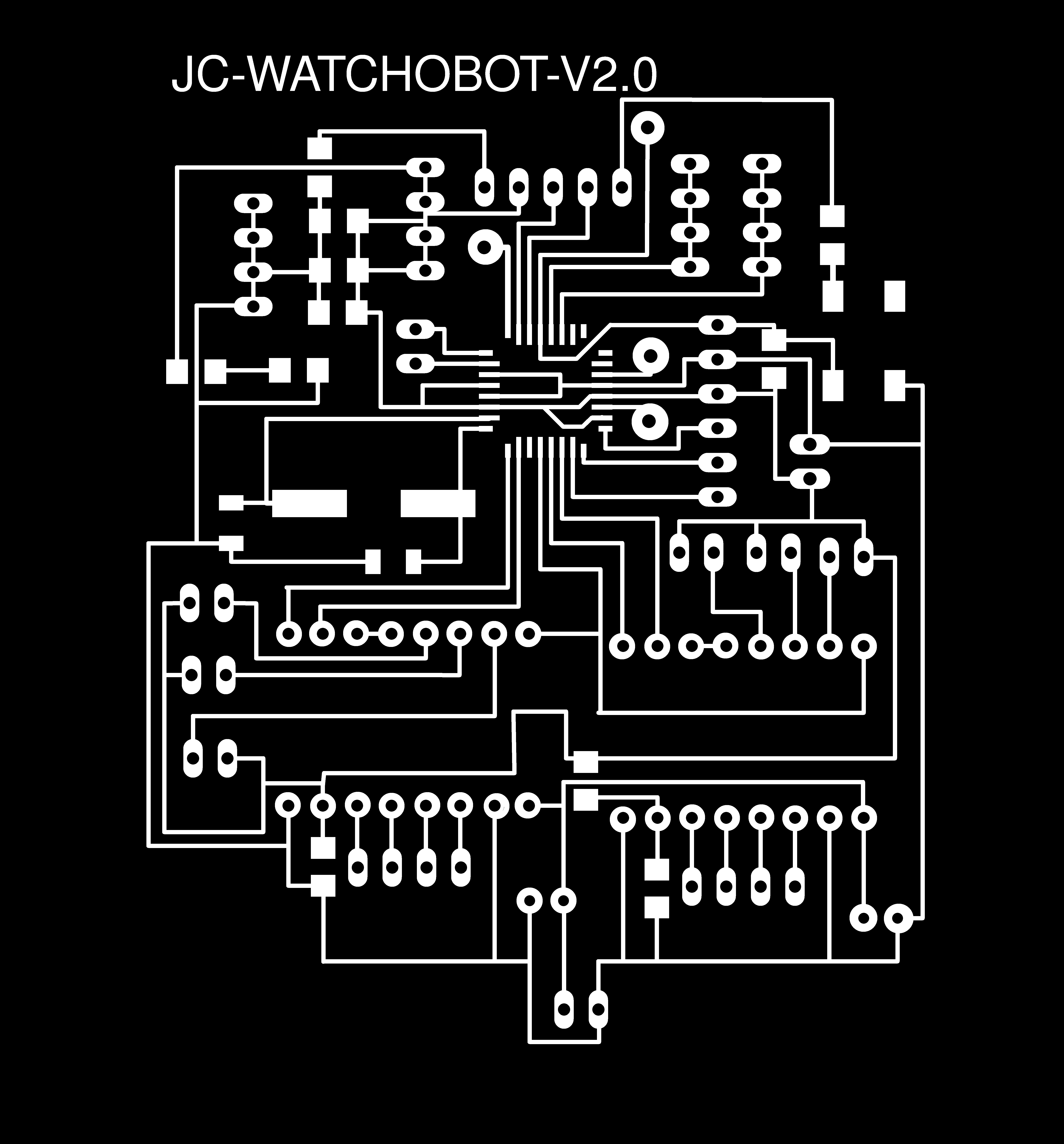
Further details can be found here.
I burned the bootloader using Arduino IDE to test the board is working:
/home/jc/Program Files/arduino-1.8.2/hardware/tools/avr/bin/avrdude -C/home/jc/Program Files/arduino-1.8.2/hardware/tools/avr/etc/avrdude.conf -v -patmega328p -cstk500v1 -P/dev/ttyACM3 -b19200 -e -Ulock:w:0x3F:m -Uefuse:w:0xFD:m -Uhfuse:w:0xDE:m -Ulfuse:w:0xFF:m

avrdude: Version 6.3, compiled on Jan 17 2017 at 11:00:16
         Copyright (c) 2000-2005 Brian Dean, http://www.bdmicro.com/
         Copyright (c) 2007-2014 Joerg Wunsch

         System wide configuration file is "/home/jc/Program Files/arduino-1.8.2/hardware/tools/avr/etc/avrdude.conf"
         User configuration file is "/home/jc/.avrduderc"
         User configuration file does not exist or is not a regular file, skipping

         Using Port                    : /dev/ttyACM3
         Using Programmer              : stk500v1
         Overriding Baud Rate          : 19200
         AVR Part                      : ATmega328P
         Chip Erase delay              : 9000 us
         PAGEL                         : PD7
         BS2                           : PC2
         RESET disposition             : dedicated
         RETRY pulse                   : SCK
         serial program mode           : yes
         parallel program mode         : yes
         Timeout                       : 200
         StabDelay                     : 100
         CmdexeDelay                   : 25
         SyncLoops                     : 32
         ByteDelay                     : 0
         PollIndex                     : 3
         PollValue                     : 0x53
         Memory Detail                 :

                                  Block Poll               Page                       Polled
           Memory Type Mode Delay Size  Indx Paged  Size   Size #Pages MinW  MaxW   ReadBack
           ----------- ---- ----- ----- ---- ------ ------ ---- ------ ----- ----- ---------
           eeprom        65    20     4    0 no       1024    4      0  3600  3600 0xff 0xff
           flash         65     6   128    0 yes     32768  128    256  4500  4500 0xff 0xff
           lfuse          0     0     0    0 no          1    0      0  4500  4500 0x00 0x00
           hfuse          0     0     0    0 no          1    0      0  4500  4500 0x00 0x00
           efuse          0     0     0    0 no          1    0      0  4500  4500 0x00 0x00
           lock           0     0     0    0 no          1    0      0  4500  4500 0x00 0x00
           calibration    0     0     0    0 no          1    0      0     0     0 0x00 0x00
           signature      0     0     0    0 no          3    0      0     0     0 0x00 0x00

         Programmer Type : STK500
         Description     : Atmel STK500 Version 1.x firmware
         Hardware Version: 2
         Firmware Version: 1.18
         Topcard         : Unknown
         Vtarget         : 0.0 V
         Varef           : 0.0 V
         Oscillator      : Off
         SCK period      : 0.1 us

avrdude: AVR device initialized and ready to accept instructions

Reading | ################################################## | 100% 0.02s

avrdude: Device signature = 0x1e950f (probably m328p)
avrdude: erasing chip
avrdude: reading input file "0x3F"
avrdude: writing lock (1 bytes):

Writing | ################################################## | 100% 0.01s

avrdude: 1 bytes of lock written
avrdude: verifying lock memory against 0x3F:
avrdude: load data lock data from input file 0x3F:
avrdude: input file 0x3F contains 1 bytes
avrdude: reading on-chip lock data:

Reading | ################################################## | 100% 0.01s

avrdude: verifying ...
avrdude: 1 bytes of lock verified
avrdude: reading input file "0xFD"
avrdude: writing efuse (1 bytes):

Writing | ################################################## | 100% 0.02s

avrdude: 1 bytes of efuse written
avrdude: verifying efuse memory against 0xFD:
avrdude: load data efuse data from input file 0xFD:
avrdude: input file 0xFD contains 1 bytes
avrdude: reading on-chip efuse data:

Reading | ################################################## | 100% 0.01s

avrdude: verifying ...
avrdude: 1 bytes of efuse verified
avrdude: reading input file "0xDE"
avrdude: writing hfuse (1 bytes):

Writing | ################################################## | 100% 0.02s

avrdude: 1 bytes of hfuse written
avrdude: verifying hfuse memory against 0xDE:
avrdude: load data hfuse data from input file 0xDE:
avrdude: input file 0xDE contains 1 bytes
avrdude: reading on-chip hfuse data:

Reading | ################################################## | 100% 0.01s

avrdude: verifying ...
avrdude: 1 bytes of hfuse verified
avrdude: reading input file "0xFF"
avrdude: writing lfuse (1 bytes):

/home/jc/Program Files/arduino-1.8.2/hardware/tools/avr/bin/avrdude -C/home/jc/Program Files/arduino-1.8.2/hardware/tools/avr/etc/avrdude.conf -v -patmega328p -cstk500v1 -P/dev/ttyACM3 -b19200 -Uflash:w:/home/jc/Program Files/arduino-1.8.2/hardware/arduino/avr/bootloaders/optiboot/optiboot_atmega328.hex:i -Ulock:w:0x0F:m

avrdude: Version 6.3, compiled on Jan 17 2017 at 11:00:16
         Copyright (c) 2000-2005 Brian Dean, http://www.bdmicro.com/
         Copyright (c) 2007-2014 Joerg Wunsch

         System wide configuration file is "/home/jc/Program Files/arduino-1.8.2/hardware/tools/avr/etc/avrdude.conf"
         User configuration file is "/home/jc/.avrduderc"
         User configuration file does not exist or is not a regular file, skipping

         Using Port                    : /dev/ttyACM3
         Using Programmer              : stk500v1
         Overriding Baud Rate          : 19200
Writing | ################################################## | 100% 0.02s

avrdude: 1 bytes of lfuse written
avrdude: verifying lfuse memory against 0xFF:
avrdude: load data lfuse data from input file 0xFF:
avrdude: input file 0xFF contains 1 bytes
avrdude: reading on-chip lfuse data:

Reading | ################################################## | 100% 0.01s

avrdude: verifying ...
avrdude: 1 bytes of lfuse verified

avrdude done.  Thank you.

         AVR Part                      : ATmega328P
         Chip Erase delay              : 9000 us
         PAGEL                         : PD7
         BS2                           : PC2
         RESET disposition             : dedicated
         RETRY pulse                   : SCK
         serial program mode           : yes
         parallel program mode         : yes
         Timeout                       : 200
         StabDelay                     : 100
         CmdexeDelay                   : 25
         SyncLoops                     : 32
         ByteDelay                     : 0
         PollIndex                     : 3
         PollValue                     : 0x53
         Memory Detail                 :

                                  Block Poll               Page                       Polled
           Memory Type Mode Delay Size  Indx Paged  Size   Size #Pages MinW  MaxW   ReadBack
           ----------- ---- ----- ----- ---- ------ ------ ---- ------ ----- ----- ---------
           eeprom        65    20     4    0 no       1024    4      0  3600  3600 0xff 0xff
           flash         65     6   128    0 yes     32768  128    256  4500  4500 0xff 0xff
           lfuse          0     0     0    0 no          1    0      0  4500  4500 0x00 0x00
           hfuse          0     0     0    0 no          1    0      0  4500  4500 0x00 0x00
           efuse          0     0     0    0 no          1    0      0  4500  4500 0x00 0x00
           lock           0     0     0    0 no          1    0      0  4500  4500 0x00 0x00
           calibration    0     0     0    0 no          1    0      0     0     0 0x00 0x00
           signature      0     0     0    0 no          3    0      0     0     0 0x00 0x00

         Programmer Type : STK500
         Description     : Atmel STK500 Version 1.x firmware
         Hardware Version: 2
         Firmware Version: 1.18
         Topcard         : Unknown
         Vtarget         : 0.0 V
         Varef           : 0.0 V
         Oscillator      : Off
         SCK period      : 0.1 us

avrdude: AVR device initialized and ready to accept instructions

Reading | ################################################## | 100% 0.02s

avrdude: Device signature = 0x1e950f (probably m328p)
avrdude: NOTE: "flash" memory has been specified, an erase cycle will be performed
         To disable this feature, specify the -D option.
avrdude: erasing chip
avrdude: reading input file "/home/jc/Program Files/arduino-1.8.2/hardware/arduino/avr/bootloaders/optiboot/optiboot_atmega328.hex"
avrdude: writing flash (32768 bytes):

Writing | ################################################## | 100% 0.00s

avrdude: 32768 bytes of flash written
avrdude: verifying flash memory against /home/jc/Program Files/arduino-1.8.2/hardware/arduino/avr/bootloaders/optiboot/optiboot_atmega328.hex:
avrdude: load data flash data from input file /home/jc/Program Files/arduino-1.8.2/hardware/arduino/avr/bootloaders/optiboot/optiboot_atmega328.hex:
avrdude: input file /home/jc/Program Files/arduino-1.8.2/hardware/arduino/avr/bootloaders/optiboot/optiboot_atmega328.hex contains 32768 bytes
avrdude: reading on-chip flash data:

Reading | ################################################## | 100% 0.00s

avrdude: verifying ...
avrdude: 32768 bytes of flash verified
avrdude: reading input file "0x0F"
avrdude: writing lock (1 bytes):

Writing | ################################################## | 100% 0.02s

avrdude: 1 bytes of lock written
avrdude: verifying lock memory against 0x0F:
avrdude: load data lock data from input file 0x0F:
avrdude: input file 0x0F contains 1 bytes
avrdude: reading on-chip lock data:

Reading | ################################################## | 100% 0.01s

avrdude: verifying ...
avrdude: 1 bytes of lock verified

avrdude done.  Thank you.
HTTP-SERVER AND WEB STEPPER MOTOR CONTROL
There are various libraries to control the ESP8266 module, for example, WeeESP, ESP8266_Simple or ESP8266wifi which needs pins necessary to directly program the ESP8266 board.
For this task a combination of hayes command sets and a A4988 stepper driver library.
Some information about the module commands can be found here and here.
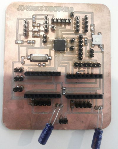
First, the board is hooked to the ESP8266 module and the stepper motor and battery.
Diagram below illustrates the wiring:

PROGRAM 1: ESP8266 WEBPAGE SERVER
The following program uses the ESP8266 module and the jc-watchobot-v2.0 board to implement a webserver.
Connections follow the schematic as described in the subsection above; however, without the stepper motor connection.
The ESP8266 module can be controlled via serial using AT commands or the hayes command set which consist of a series of short text strings that are put together for operations such as setting up a client, connecting to a wifi-router, obtaining ip address, etc.
The program below is written to create a web-server using AT commands and software serial communication.
The only library required for this code is the SoftwareSerial.h library, available by default in the Arduino IDE.
A boolean global variable is firstly defined, which can be turned on or off, depending on the user requirements.
Similarly, two global strings are added for easy modification, where the user must put the SSID of the router-wifi connection and the password, respectively.
Setup function
The setup function begins by specifying the baud rate to communicate with the ESP8266.
Similarly, software serial is initialised to monitor the connection via serial in the computer.
The next set of commands, use the function sendData.
Function sendData: This function is used to send commands to the ESP8266 via serial in order to operate the module by issuing AT commands, which are a set of strings. The function takes three arguments, the command to be sent, which is a string value, the timeout in miliseconds and a boolean (true or false) for the debugging.
The sendData function first resets the ESP8266 by issuing the command AT+RST, then it configures the module as an access point with the command AT+CWMODE=1.
Once the mode is selected, it proceeds to connect to my wifi network using the global strings where the SSID and password are stored. In this case, the command send is AT+CWJAP=ssid,pass,1000.
Next, the ip address is obtained using AT+CIFSR, multiple connections are accepted by AT+CIPMUX=1 and finally, the default port for web (i.e. 80) is used to start the server with AT+CIPSERVER=1,80
Loop function
The loop function starts by checking whether Serial is available, if it is true, after a delay, the connection ID is saved into a variable and a String is created with the webpage html content, which will be later parsed in the client.
In order to load the webpage from the client, we proceed similarly by using the AT+CIPSEND command and the sendData function.
Once CIPSEND command is issued, the ESP8266 sends data and waits for the AT+CIPCLOSE command to finish the connection.
In this way, each time the webpage is requested, the ESP8266 will send the data to the client, which in turn will load the test webpage.
The code:
#include <SoftwareSerial.h>
#define DEBUG true
String ssid =  "ssid_here";
String pass = "passhere";
SoftwareSerial mySerial(PD3,PD4);

void setup()
{
  // Serial at 115200 baud rate of the esp8266-f.
  Serial.begin(115200);

  // software serial to monitor
  mySerial.begin(9600);

  /*
   * start server
   */
  // reset module
  sendData("AT+RST\r\n",2000,DEBUG);
  // configure as access point
  sendData("AT+CWMODE=1\r\n",1000,DEBUG);
  // connect to wifi
  sendData("AT+CWJAP=\"" + ssid +"\",\"" + pass + "\"", 1000, DEBUG);
  // get ip address
  sendData("AT+CIFSR\r\n",1000,DEBUG);
  // configure multiple connections
  sendData("AT+CIPMUX=1\r\n",1000,DEBUG);
  // use port 80 and turn on the server
  sendData("AT+CIPSERVER=1,80\r\n",1000,DEBUG);
}

void loop()
{

  /*  ************************
   *  Parse webpage
   *  ************************/
  if(Serial.available()) // check if the esp is sending a message
  {
     delay(1000);

     int connectionId = Serial.read()-48; // subtract 48 because the read() function returns
                                           // the ASCII decimal value and 0 (the first decimal number) starts at 48

     String webpage = "<html> <h1>JC FabAcademy 2017</h1><hr>";
     webpage += "<iframe width=\"560\" height=\"315\" src=\"https://www.youtube.com/embed/DLzxrzFCyOs\" frameborder=\"0\" allowfullscreen></iframe>";

     String cipSend = "AT+CIPSEND=";
     cipSend += connectionId;
     cipSend += ",";
     cipSend +=webpage.length();
     cipSend +="\r\n";

     sendData(cipSend,1000,DEBUG);
     sendData(webpage,1000,DEBUG);

     String closeCommand = "AT+CIPCLOSE=";
     closeCommand+=connectionId; // append connection id
     closeCommand+="\r\n";

     sendData(closeCommand,3000,DEBUG);
  }
}

/*
* sendData function: Sends command to the ESP8266 and returns response.
*/
String sendData(String command, const int timeout, boolean debug)
{
    String response = "";

    Serial.print(command); // send the read character to the mySerial

    long int time = millis();

    while( (time+timeout) > millis())
    {
      while(Serial.available())
      {

        // The esp has data so display its output to the serial window
        char c = Serial.read(); // read the next character.
        response+=c;
      }
    }

    if(debug)
    {
      mySerial.print(response);
    }

    return response;
}
Code is uploaded using arduino as ISP:
avrdude: Version 6.3, compiled on Jan 17 2017 at 11:00:16
         Copyright (c) 2000-2005 Brian Dean, http://www.bdmicro.com/
         Copyright (c) 2007-2014 Joerg Wunsch

         System wide configuration file is "/home/jc/Program Files/arduino-1.8.2/hardware/tools/avr/etc/avrdude.conf"
         User configuration file is "/home/jc/.avrduderc"
         User configuration file does not exist or is not a regular file, skipping

         Using Port                    : /dev/ttyACM3
         Using Programmer              : stk500v1
         Overriding Baud Rate          : 19200
         AVR Part                      : ATmega328P
         Chip Erase delay              : 9000 us
         PAGEL                         : PD7
         BS2                           : PC2
         RESET disposition             : dedicated
         RETRY pulse                   : SCK
         serial program mode           : yes
         parallel program mode         : yes
         Timeout                       : 200
         StabDelay                     : 100
         CmdexeDelay                   : 25
         SyncLoops                     : 32
         ByteDelay                     : 0
         PollIndex                     : 3
         PollValue                     : 0x53
         Memory Detail                 :

                                  Block Poll               Page                       Polled
           Memory Type Mode Delay Size  Indx Paged  Size   Size #Pages MinW  MaxW   ReadBack
           ----------- ---- ----- ----- ---- ------ ------ ---- ------ ----- ----- ---------
           eeprom        65    20     4    0 no       1024    4      0  3600  3600 0xff 0xff
           flash         65     6   128    0 yes     32768  128    256  4500  4500 0xff 0xff
           lfuse          0     0     0    0 no          1    0      0  4500  4500 0x00 0x00
           hfuse          0     0     0    0 no          1    0      0  4500  4500 0x00 0x00
           efuse          0     0     0    0 no          1    0      0  4500  4500 0x00 0x00
           lock           0     0     0    0 no          1    0      0  4500  4500 0x00 0x00
           calibration    0     0     0    0 no          1    0      0     0     0 0x00 0x00
           signature      0     0     0    0 no          3    0      0     0     0 0x00 0x00

         Programmer Type : STK500
         Description     : Atmel STK500 Version 1.x firmware
         Hardware Version: 2
         Firmware Version: 1.18
         Topcard         : Unknown
         Vtarget         : 0.0 V
         Varef           : 0.0 V
         Oscillator      : Off
         SCK period      : 0.1 us

avrdude: AVR device initialized and ready to accept instructions

Reading | ################################################## | 100% 0.02s

avrdude: Device signature = 0x1e950f (probably m328p)
avrdude: NOTE: "flash" memory has been specified, an erase cycle will be performed
         To disable this feature, specify the -D option.
avrdude: erasing chip
avrdude: reading input file "/tmp/arduino_build_781939/sketch_may20a.ino.hex"
avrdude: writing flash (6372 bytes):

Writing | ################################################## | 100% 6.97s

avrdude: 6372 bytes of flash written
avrdude: verifying flash memory against /tmp/arduino_build_781939/sketch_may20a.ino.hex:
avrdude: load data flash data from input file /tmp/arduino_build_781939/sketch_may20a.ino.hex:
avrdude: input file /tmp/arduino_build_781939/sketch_may20a.ino.hex contains 6372 bytes
avrdude: reading on-chip flash data:

Reading | ################################################## | 100% 3.89s

avrdude: verifying ...
avrdude: 6372 bytes of flash verified

avrdude done.  Thank you.
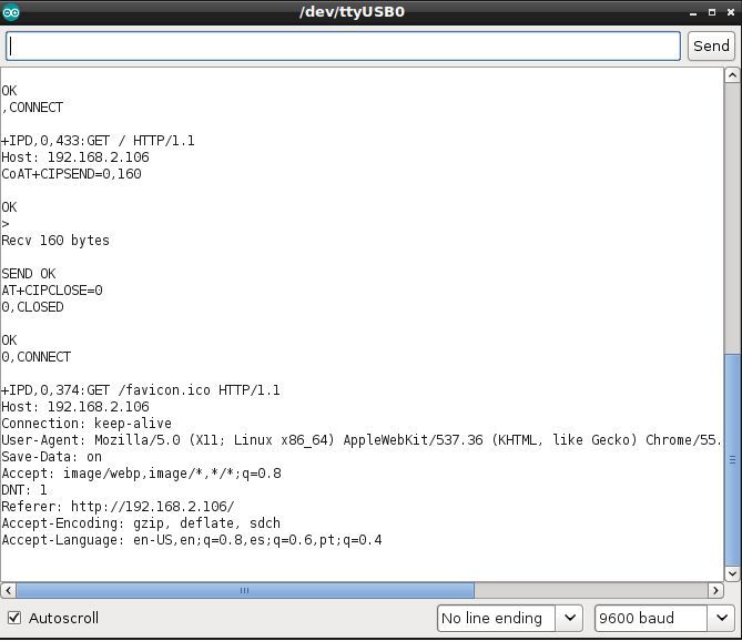
Using an ftdi cable to check the serial output, the program worked as expected:
A video of the web-server in action:
PROGRAM 2: WEB CONTROL OF STEPPER MOTOR
Next, an stepper motor is controlled wirelessly using a local webpage.
Similar to the website server above, AT commands are sent to the ESP8266 module by serial using the same sendData function.
For this, a library is used to set up the stepper motors.
Pololu offers an arduino library for their A4988 stepper motor driver.
It can be found here: https://github.com/laurb9/StepperDriver
First, the stepper motors are set-up using the A4988.h library. It needs for this case, the step/revolution setting (for my steppers this value is 200), the direction pin, the step pin and the ms1, ms2, ms3 pins (which are optional for microstepping).
The ESP8266 is then initialised as before using AT commands in the setup function.
Additionally, the stepper motor is also initialised. stepper.setRPM sets the rpm of the stepper motor as the name implies and stepper.setMicrostep(), sets the microstepping of the stepper motor, where 1 indicates full speed.
In the main loop function, communication is between the board and the ESP8266 is checked by using the conditional if(Serial.available()).
Similarly, Serial.find function is used to search for the start of the string +IPD. This is the string that the ESP8266 receives once a get or post request is sent using a client computer.
After the string is found, the substring stepper= is searched for and the 'state number' saved in the variable stepperNumber, which indicates what type of movement the stepper motor will do.
In this way, the stepper motor will move forward when the serial receives "stepper=1", stops when "stepper=2" and goes backwards when "stepper=3".
The commands are sent via a computer webpage to the ESP8266 using post or get request.
This code takes some inspiration from allaboutee blog.
#include <SoftwareSerial.h>


// Set up stepper
#include <Arduino.h>
#include "A4988.h"

// using a 200-step motor (most common)
// pins used are DIR, STEP, MS1, MS2, MS3 in that order
A4988 stepper(200, PD5, PD6, PC2, PC3, PD7);

#define DEBUG true

String ssid =  "ssid";
String pass = "wifipasshere";
SoftwareSerial mySerial(PD3,PD4); // make RX Arduino line is pin 2, make TX Arduino line is pin 3.
                             // This means that you need to connect the TX line from the esp to the Arduino's pin 2
                             // and the RX line from the esp to the Arduino's pin 3
void setup()
{
  Serial.begin(115200);
  mySerial.begin(9600); // your esp's baud rate might be different

  sendData("AT+RST\r\n",2000,DEBUG); // reset module
  sendData("AT+CWMODE=1\r\n",1000,DEBUG); // configure as access point
  sendData("AT+CWJAP=\"" + ssid +"\",\"" + pass + "\"", 1000, DEBUG);
  sendData("AT+CIFSR\r\n",1000,DEBUG); // get ip address
  sendData("AT+CIPMUX=1\r\n",1000,DEBUG); // configure for multiple connections
  sendData("AT+CIPSERVER=1,80\r\n",1000,DEBUG); // turn on server on port 80

  // set up stepper motor
  // Set target motor RPM to 1RPM
  stepper.setRPM(10);
  // Set full speed mode (microstepping also works for smoother hand movement
  stepper.setMicrostep(1);
  //stepper.rotate(360);

}

void loop()
{
  // motor control
    if(Serial.available()) // check if the esp is sending a message
  {
    if(Serial.find("+IPD,"))
    {
      mySerial.print("moving motor");
      delay(1000); // wait for the serial buffer to fill up (read all the serial data)
      // get the connection id so that we can then disconnect
      int connectionId = Serial.read()-48; // subtract 48 because the read() function returns
                                   // the ASCII decimal value and 0 (the first decimal number) starts at 48

      Serial.find("stepper="); // advance cursor to "stepper="
      int stepperNumber = (Serial.read()-48); // get number

      //go forward
        if (stepperNumber == 1){
          stepper.rotate(360);
        }

        if (stepperNumber == 2){
          stepper.rotate(0);
        }

        if (stepperNumber == 3){
          stepper.rotate(-360);
        }

        else {
          mySerial.print("error moving");
        }

      // make close command
      String closeCommand = "AT+CIPCLOSE=";
      closeCommand+=connectionId; // append connection id
      closeCommand+="\r\n";

      sendData(closeCommand,1000,DEBUG); // close connection
    }
  }
}

/*
* Name: sendData
*/
String sendData(String command, const int timeout, boolean debug)
{
    String response = "";

    Serial.print(command); // send the read character to the mySerial

    long int time = millis();

    while( (time+timeout) > millis())
    {
      while(Serial.available())
      {

        // The esp has data so display its output to the serial window
        char c = Serial.read(); // read the next character.
        response+=c;
      }
    }

    if(debug)
    {
      mySerial.print(response);
    }

    return response;
}
Code above worked but is not responsive enough.
For motor to move, with this code, whenever a request is sent with the browser in the format: x.x.x.x/?stepper=y ; where x.x.x.x represent the local ip address of the esp8266 and y is either 1,2 or 3, depending on the action required.
Code is greatly improved by the use of serial events, which act as some sort of interrupts on the main loop of the program:
#include <SoftwareSerial.h>
#define DEBUG true
String ssid =  "wifiSSID here";
String pass = "wifipasshere";
SoftwareSerial mySerial(PD3,PD4);

// Set up stepper
#include <Arduino.h>
#include "A4988.h"

// using a 200-step motor (most common)
// pins used are DIR, STEP, MS1, MS2, MS3 in that order
A4988 stepper(200, PD5, PD6, PC2, PC3, PD7);

// function declarations
String sendData(String command, const int timeout, boolean debug);

// function data
const byte numChars = 32;
char receivedChars[numChars];
boolean newData = false;

void setup()
{
  // Serial at 115200 baud rate of the esp8266-f.
  Serial.begin(115200);

  // software serial to monitor
  mySerial.begin(9600);

  /*
   * start server
   */
  // reset module
  sendData("AT+RST\r\n",2000,DEBUG);
  // configure as access point
  sendData("AT+CWMODE=1\r\n",1000,DEBUG);
  // connect to wifi
  sendData("AT+CWJAP=\"" + ssid +"\",\"" + pass + "\"", 1000, DEBUG);
  // get ip address
  sendData("AT+CIFSR\r\n",1000,DEBUG);
  // configure multiple connections
  sendData("AT+CIPMUX=1\r\n",1000,DEBUG);
  // use port 80 and turn on the server
  sendData("AT+CIPSERVER=1,80\r\n",1000,DEBUG);

  // set up stepper motor
  // Set target motor RPM to 1RPM
  stepper.setRPM(50);
  // Set full speed mode (microstepping also works for smoother hand movement
  stepper.setMicrostep(10);
  stepper.rotate(30);
  stepper.rotate(-30);
}

void loop()
{
    if (Serial.available() > 0){
      if (Serial.find("stepper=1")){
      stepper.rotate(360);
      Serial.flush();
      clearInput();

      }
    else if (Serial.find("stepper=2")){
      stepper.rotate(0);
      Serial.flush();
      clearInput();

    }
    else if (Serial.find("stepper=3")){
      stepper.rotate(-360);
      Serial.flush();
      clearInput();

    }
  }
}

void serialEvent(){
  /*
  while (Serial.available()){
    if (Serial.find("stepper=1")){
      stepper.rotate(360);
      Serial.flush();
    }
    if (Serial.find("stepper=2")){
      stepper.rotate(0);
      Serial.flush();

    }
    if (Serial.find("stepper=3")){
      stepper.rotate(-360);
      Serial.flush();

    }
    //check for error
    else {
      stepper.rotate(15);
      stepper.rotate(-15);
      Serial.flush();
    }
    Serial.flush();
  }
  */


}

/*
* sendData function: Sends command to the ESP8266 and returns response.
*/
String sendData(String command, const int timeout, boolean debug)
{
    String response = "";

    Serial.print(command); // send the read character to the mySerial

    long int time = millis();

    while( (time+timeout) > millis())
    {
      while(Serial.available())
      {

        // The esp has data so display its output to the serial window
        char c = Serial.read(); // read the next character.
        response+=c;
      }
    }

    if(debug)
    {
      mySerial.print(response);
    }

    return response;
}

void recvWithStartEndMarkers() {
    static boolean recvInProgress = false;
    static byte ndx = 0;
    char startMarker = '?';
    char endMarker = '_';
    char rc;

    while (Serial.available() > 0 && newData == false) {
        rc = Serial.read();

        if (recvInProgress == true) {
            if (rc != endMarker) {
                receivedChars[ndx] = rc;
                ndx++;
                if (ndx >= numChars) {
                    ndx = numChars - 1;
                }
            }
            else {
                receivedChars[ndx] = '\0'; // terminate the string
                recvInProgress = false;
                ndx = 0;
                newData = true;
            }
        }

        else if (rc == startMarker) {
            recvInProgress = true;
        }
    }
}

void showNewData() {
    if (newData == true) {
        mySerial.print("This just in ... ");
        mySerial.println(receivedChars);
        newData = false;
    }
}

void clearInput() {
  while (Serial.available() > 0) {
    Serial.read();
}
}
I included in code above, two very useful functions, as found here. recvWithStartEndMarkers() and showNewData(), I used to debug great part of the code.
Function clearInput(), clears the input buffer; as Serial.flush() blocks arduino until all outgoing data has been sent.
At first, code was included in an serialEvent but it was more appropriate to use it in the loop body.
A small webpage is set-up to contain the button controls of the motor.
<html>
<head>
  <title>Home</title>
  <link rel="stylesheet" type="text/css" href="home.css">
  <meta charset="UTF-8">
</head>

  <h1>STEPPER MOTOR CONTROL</h1>
  <hr>

  <form action="http://192.168.2.106" method="post">
    <button name="stepper" value="1_">forward</button>
  </form>

  <form action="http://192.168.2.106" method="post">
    <button name="stepper" value="2_">stop</button>
  </form>

  <form action="http://192.168.2.106" method="post">
    <button name="stepper" value="3_">backwards</button>
  </form>

</html>
Program worked as expected but with some lag when serial communication is overloaded.

Video below illustrates the motor control:
NOTES
Loopback addresses:
::1 for IPV6
127.0.0.1 for IPV4
How to represent IPv4 address as an IPv6 address:
192.0.2.30 to ::ffff:192.0.2.30
Class C network:
Three bytes of network and one byte of host.
Netmask: network portion of the IP address.
netmask: bitwise-AND IP address.
eg. for netmask 255.255.255.0
network number of 192.0.2.30 is 192.0.2.30 AND 255.255.255.0 = 192.0.2.0

other style:
192.0.2.30/40 (where number of network bits in decimal)

for IPv6:
2002:db8::/32 or 2002:db8:5413:4028::9db9/64.
Big-endian: Number that stores the big end first. A two byte hex, is stored in two bytes, sequentially..
Little-endian: storage of bytes is reversed.
Network byte order:
Helps set the correct 'host byte order'.
convertible numbers: short(2 bytes) and long (4 bytes)
eg.
htons(): host to network short.
nthl(): network to host long
C Pointers:
& is the address-of operator - "address of"
* is the dereference operator - "value pointed to by" or "value stored at"
LESSONS LEARNED
- Learned a lot about I/O and program flow.
- Learned a lot about http methods and serial communication.
FILES
jc-watchobotv2.0 - eagle files