Week 14 - Composites
Menu
Composites
Composites are a very versatile class of materials. In general, composites describes a material which is composed of a combination of different (or equal) material. In the course of this week, I will a have a close look into fiber reinforced composites. Fibers can be natural fibers, glass fibers or aramid or carbon fibers, which is the strongest one. The most commonly used resin is based on epoxy.
These resins consist of two components, just like the polyurethane we have been using in molding and casting. Combining resin and hardener forms a thermoset after the curing process is completed. This scheme is a common industry practice, e.g. for making wind turbine blades.
So here is the assignment for Week 14:
- read the material safety data sheet (MSDS) and technical data sheet (TDS) for the resins that you're using
- design and make a 3D mold (~ft2)
- and produce a fiber composite part in it
Mold making
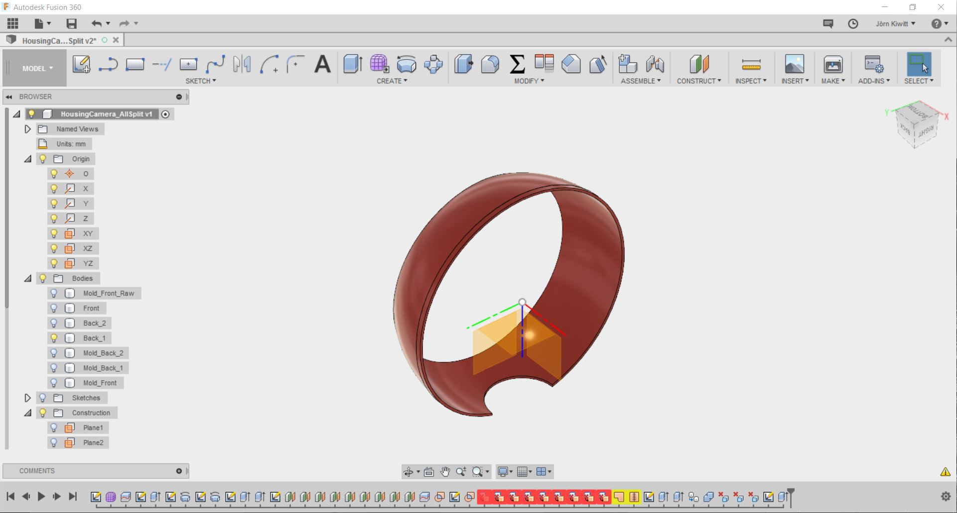
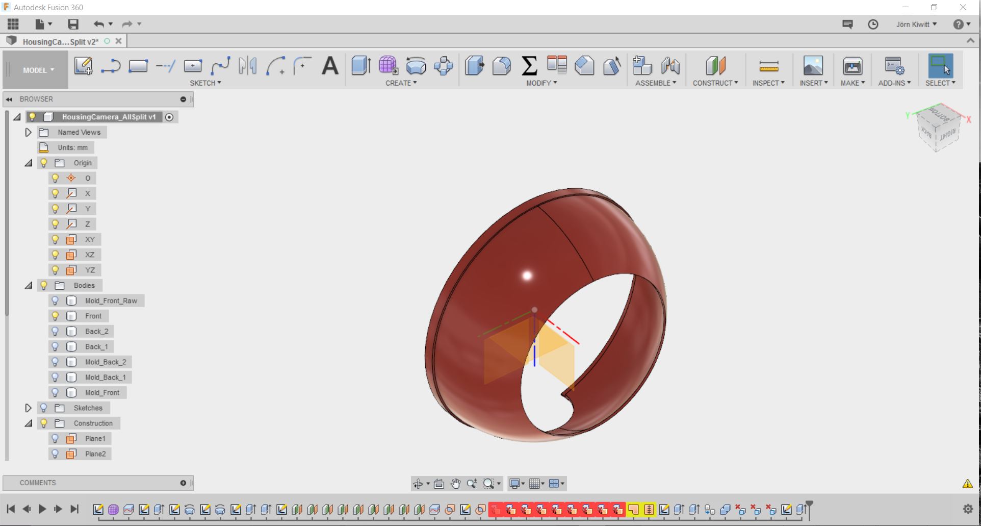
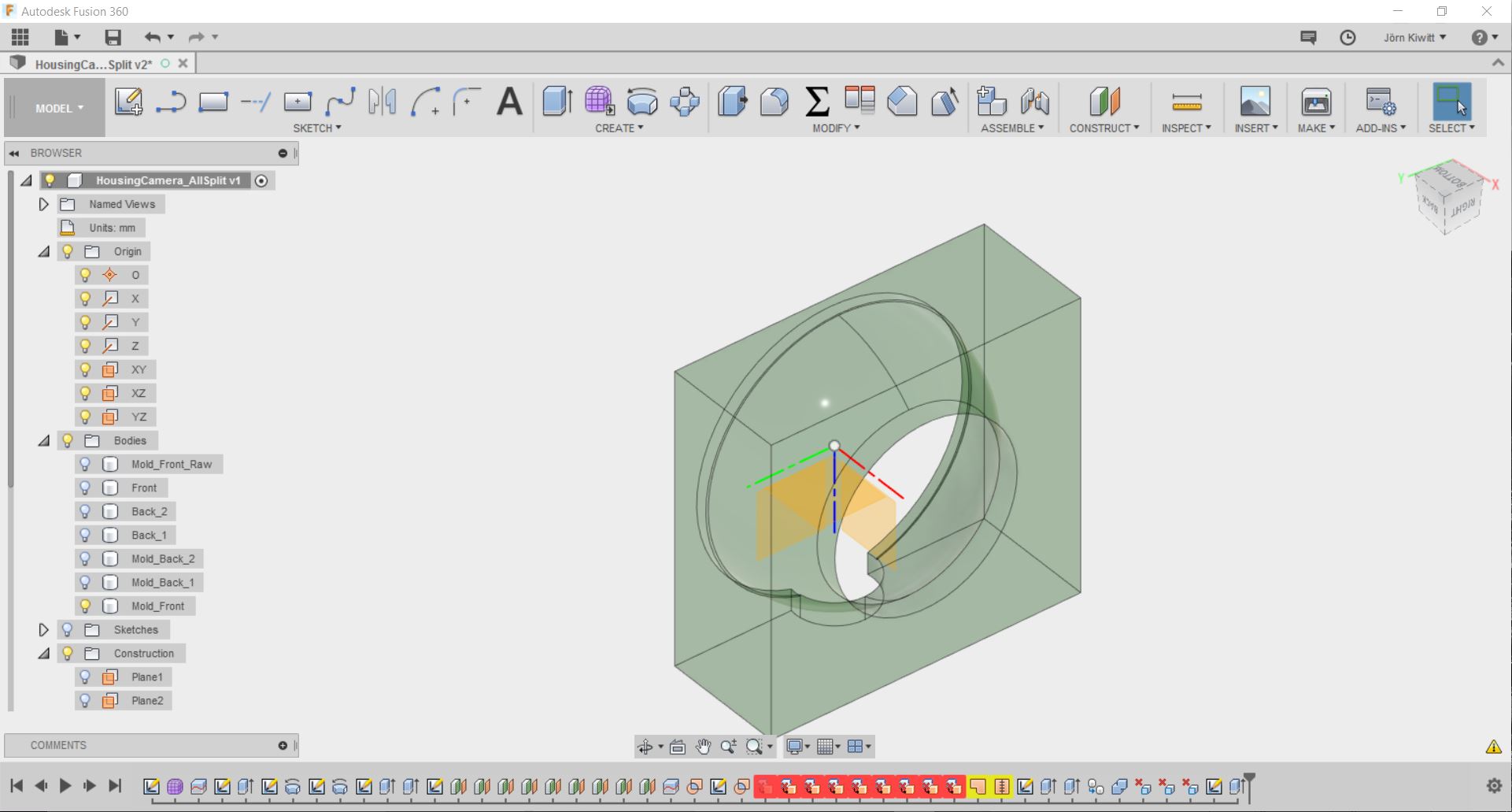
Modelling
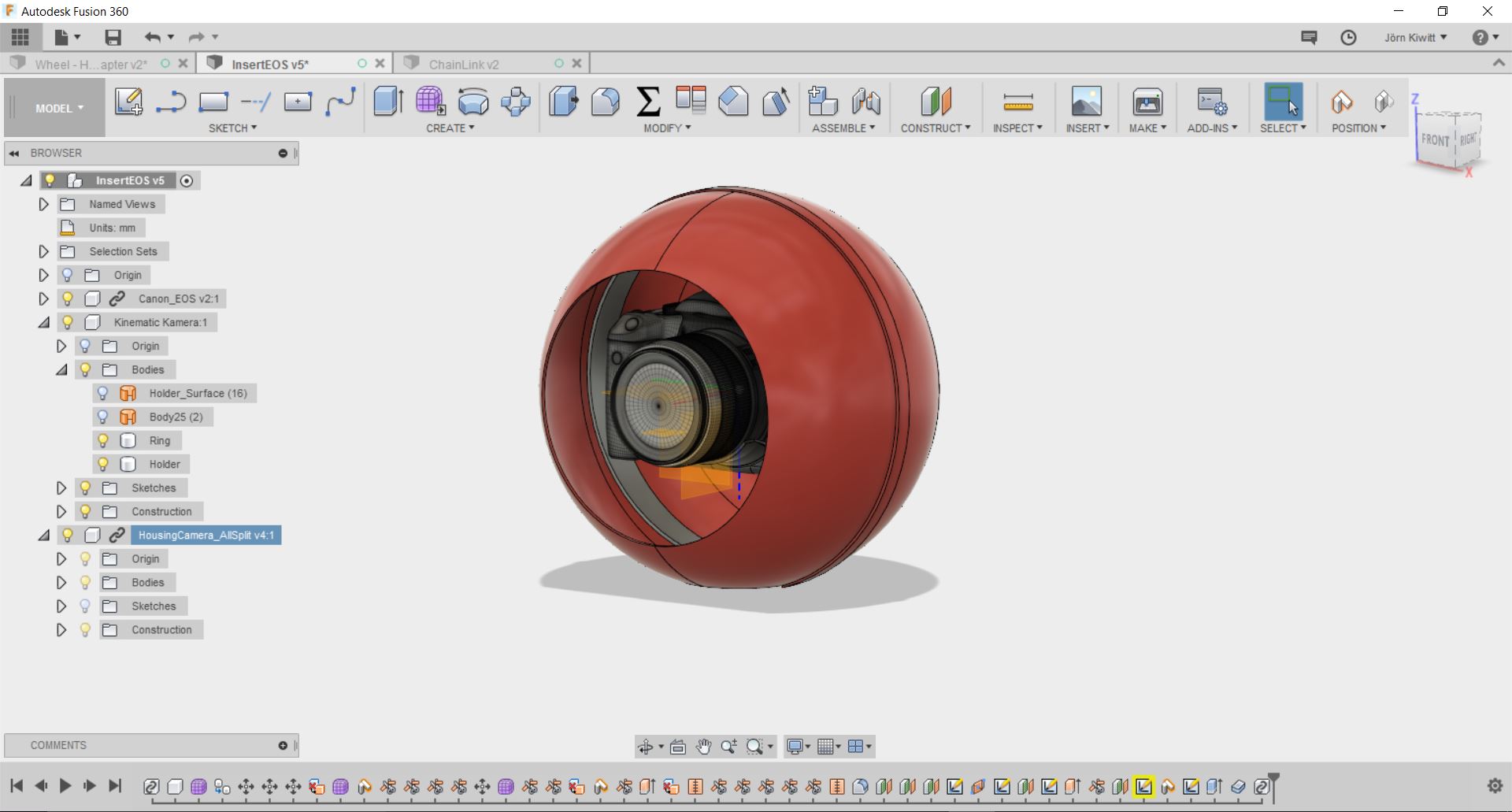
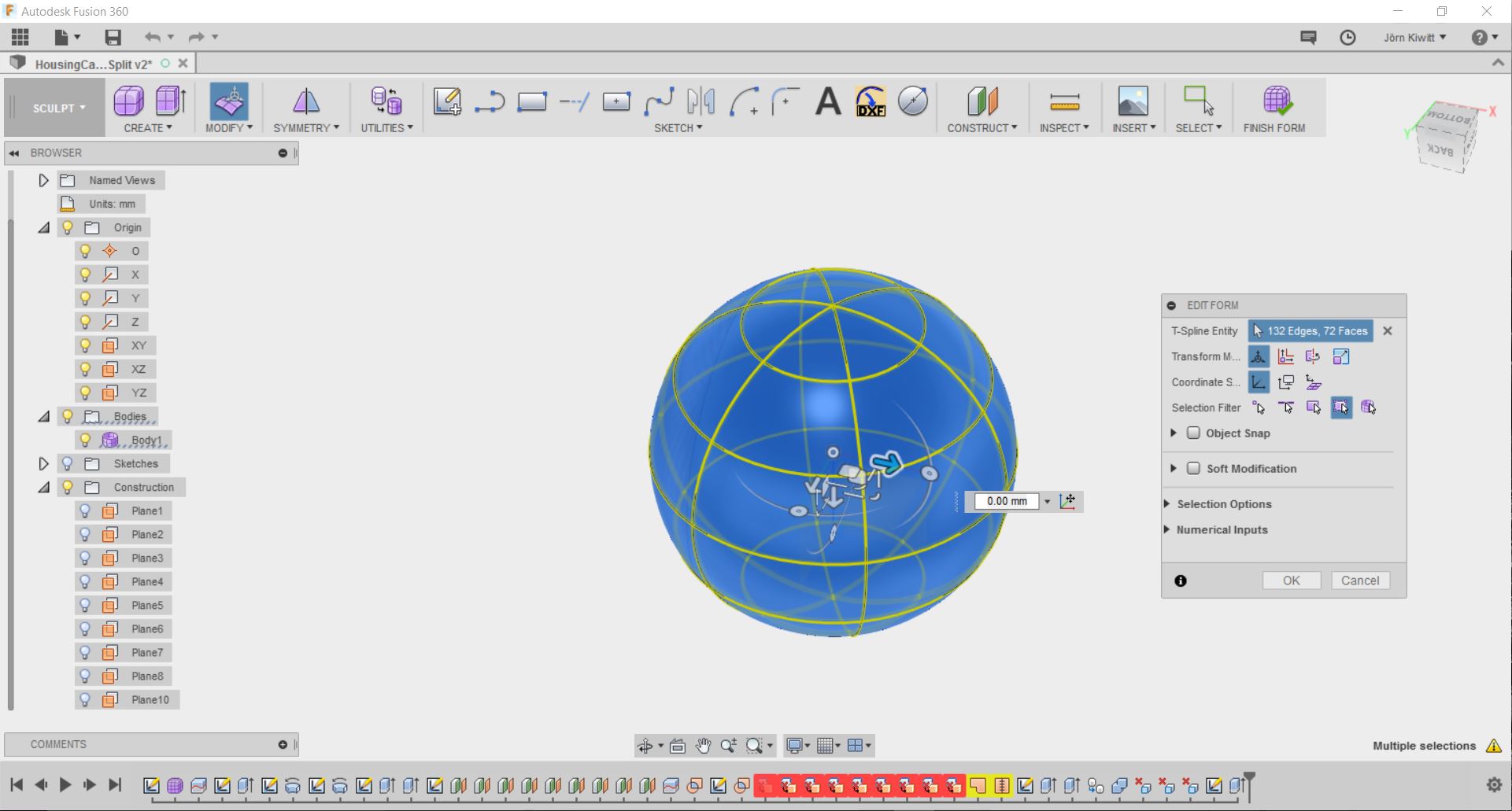
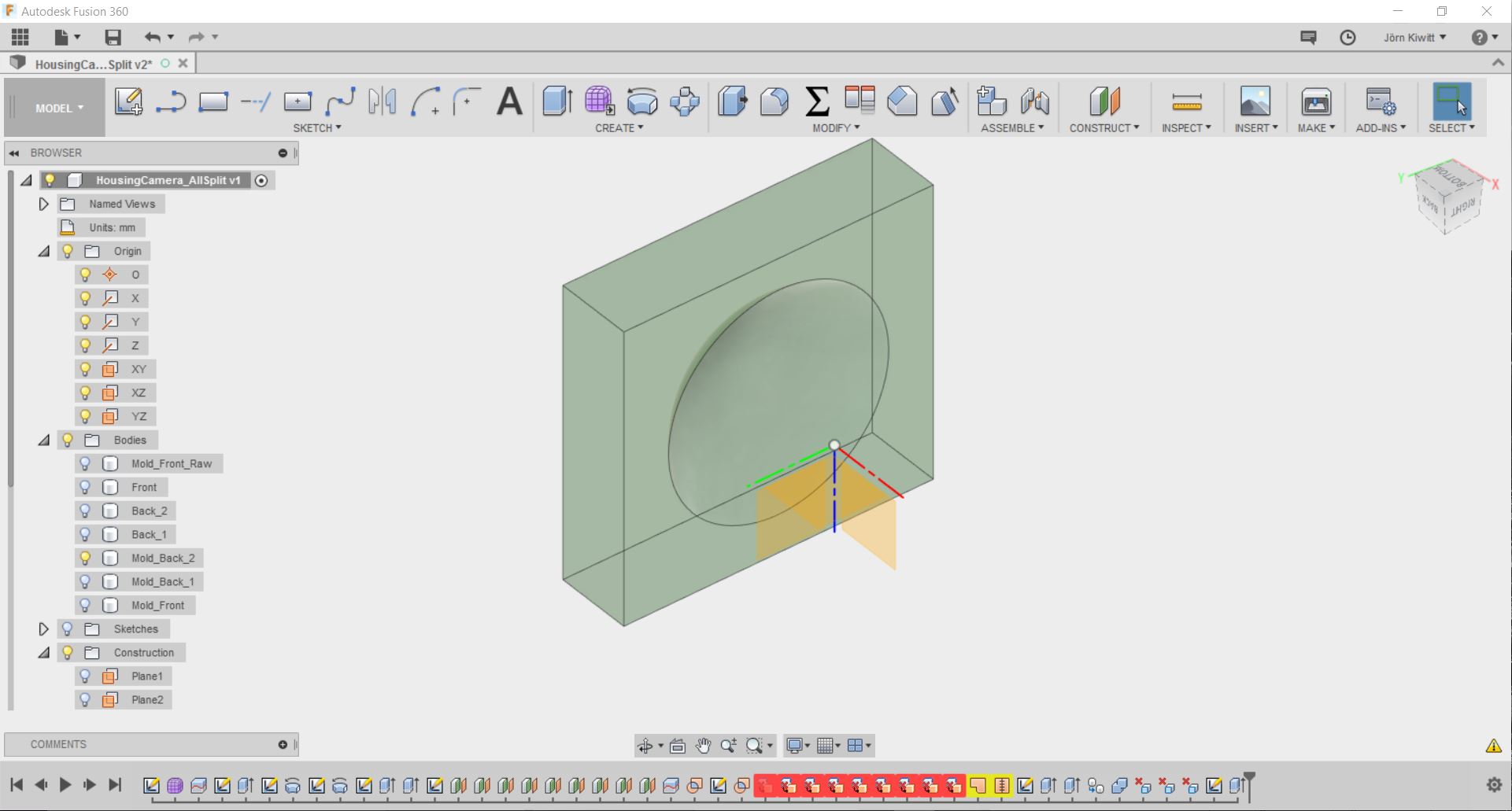
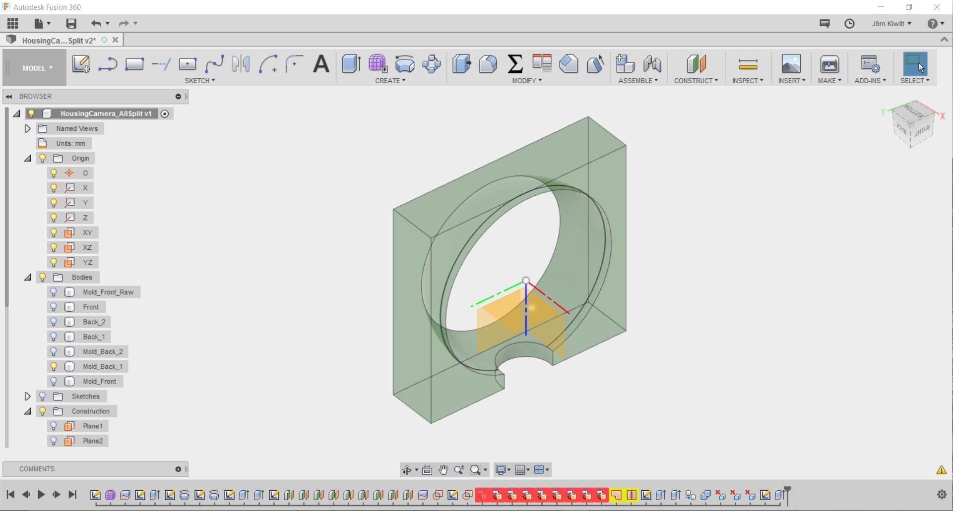
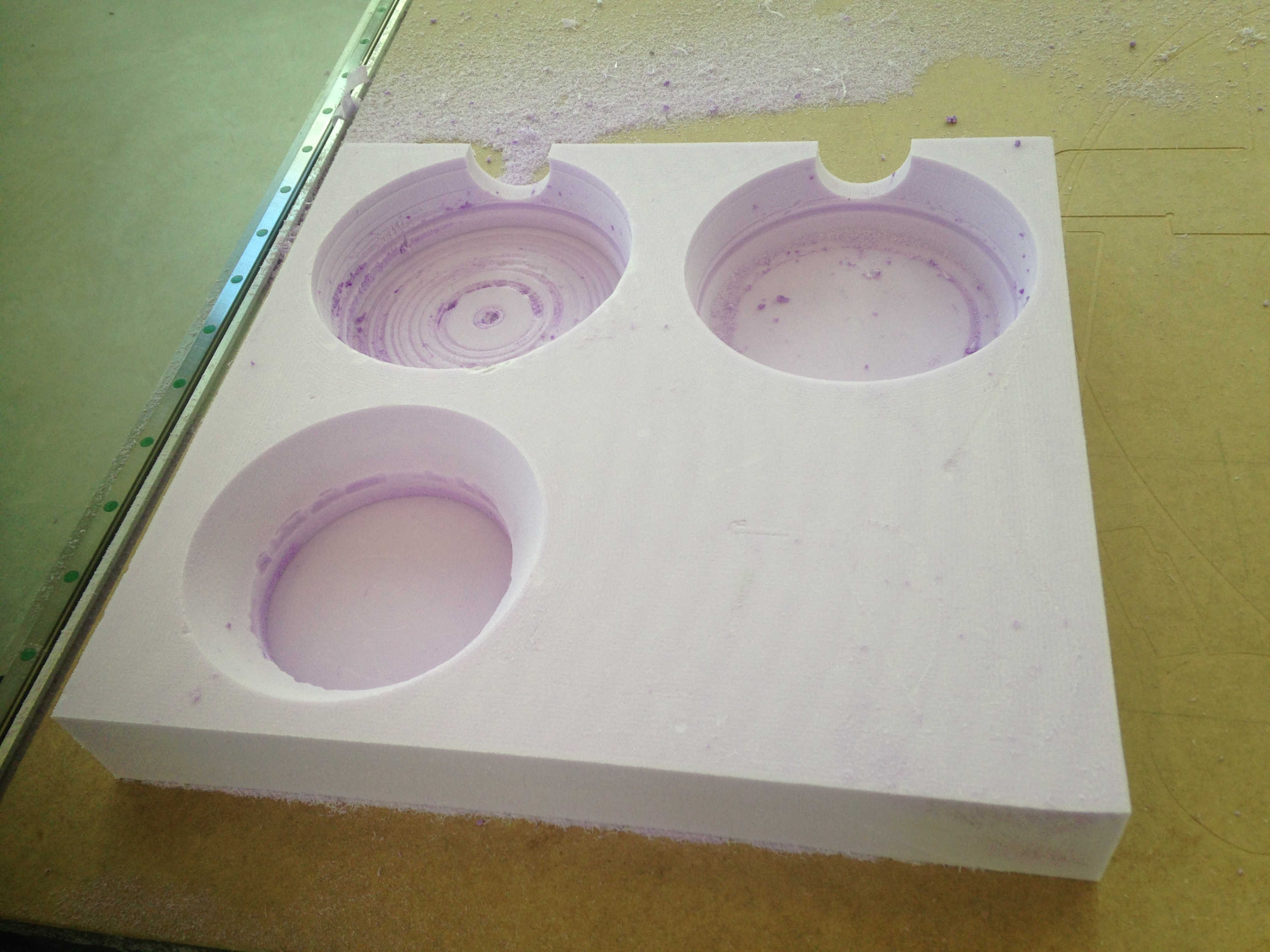
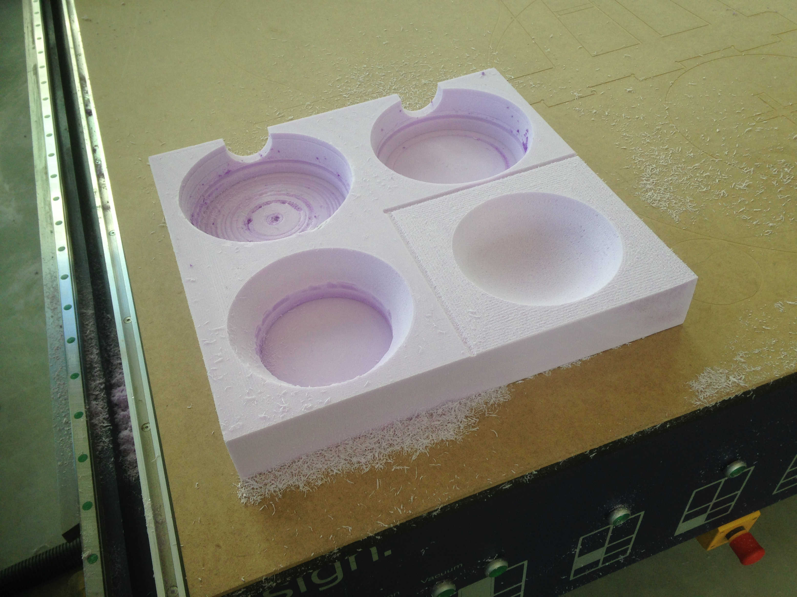
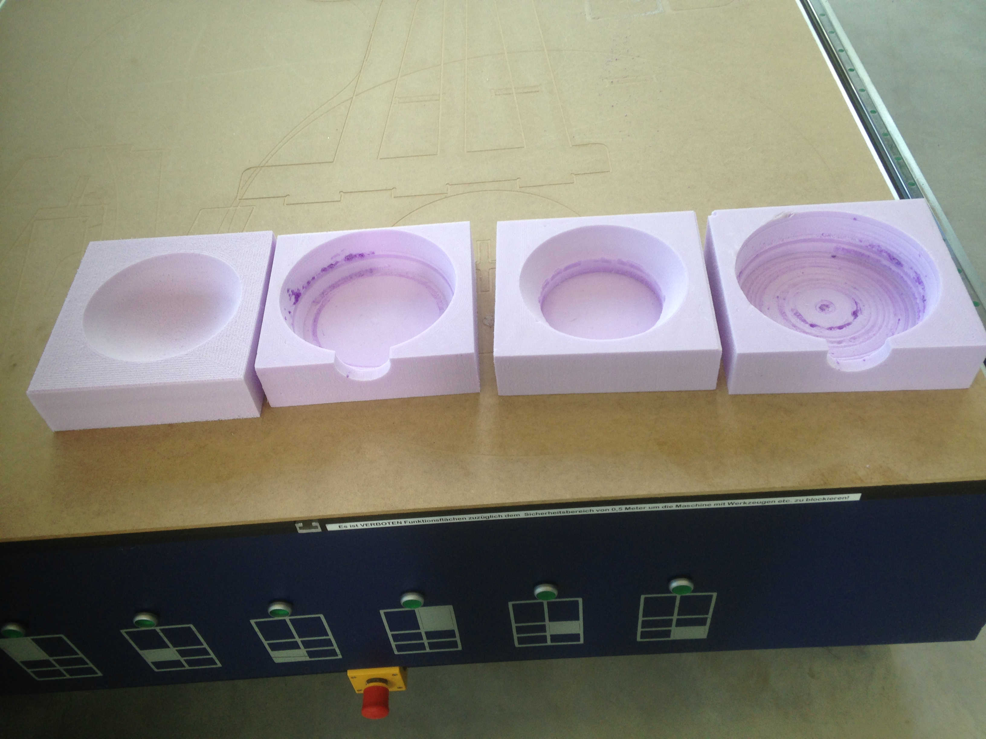
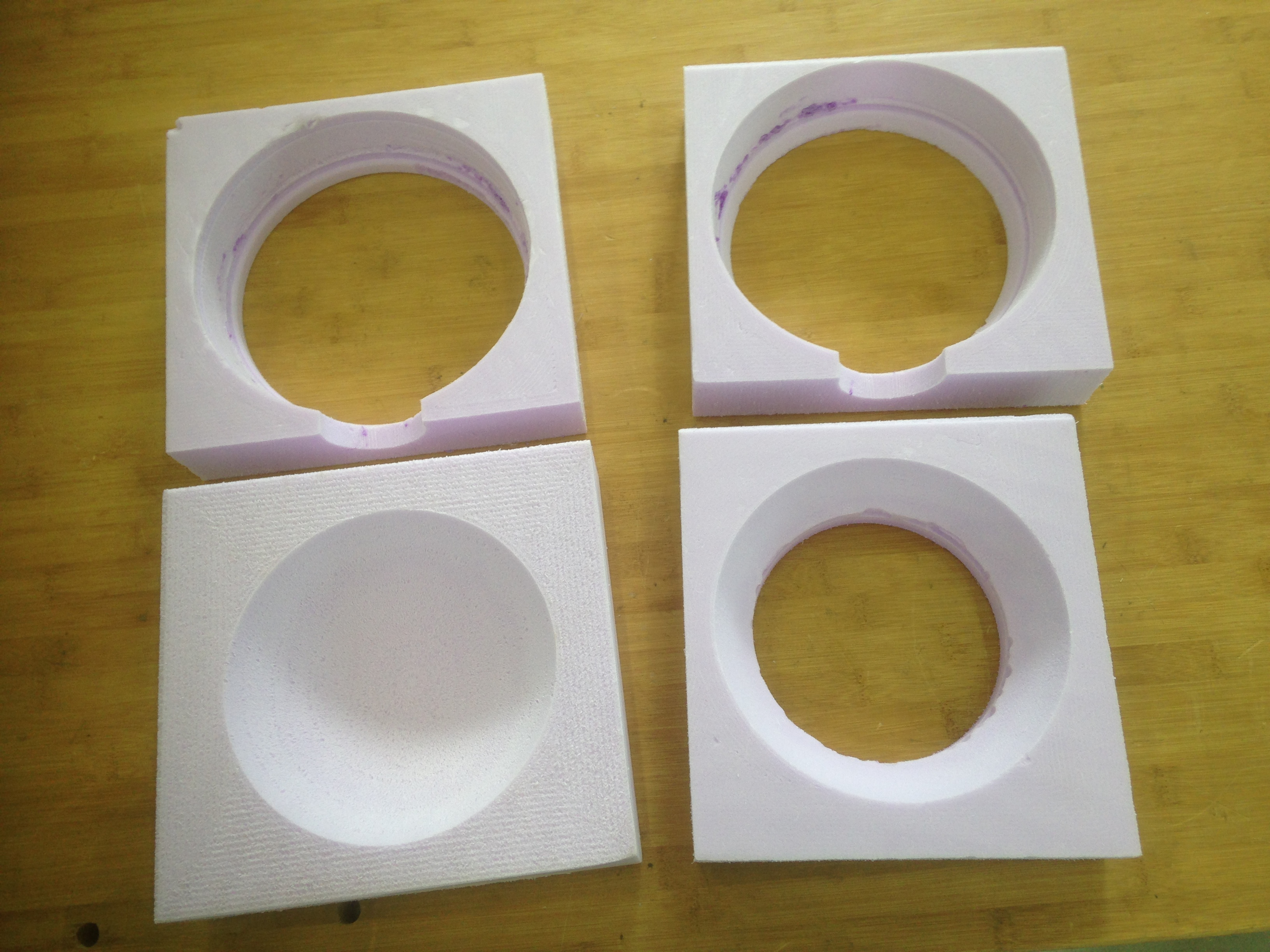
In order to create the right form, a mold is needed. I designed it in Fusion 360 and used the EasyWorker CNC machine to cut in 3D. As this router has three axis only, the freedom of design remained limited. The design should not contains undercuts. As my design is a sphere, I had to split the form. The split in the middle was necessary to enable reach of the camera after assembly. Two more splits were necessary due to limited tool length.

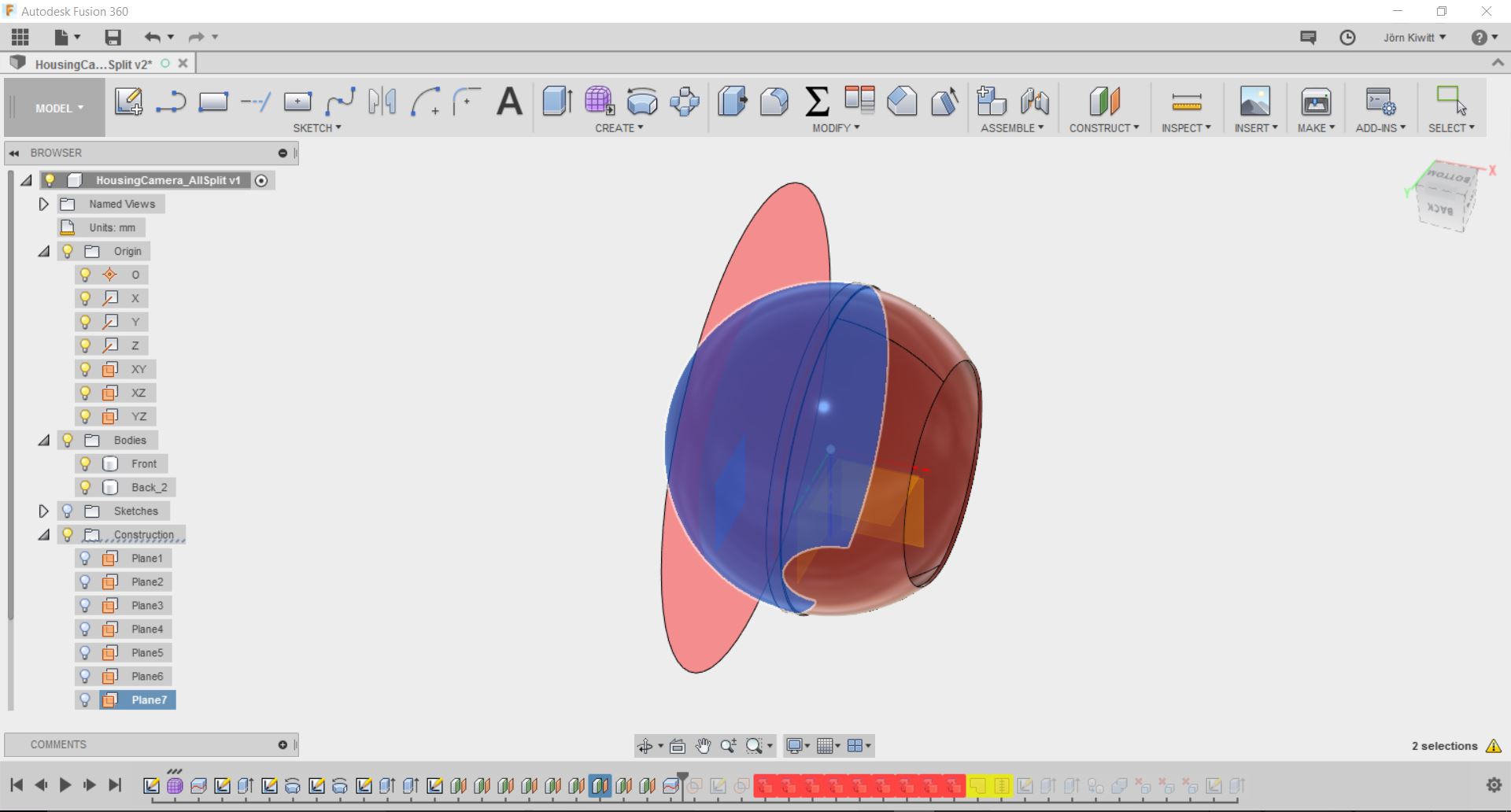
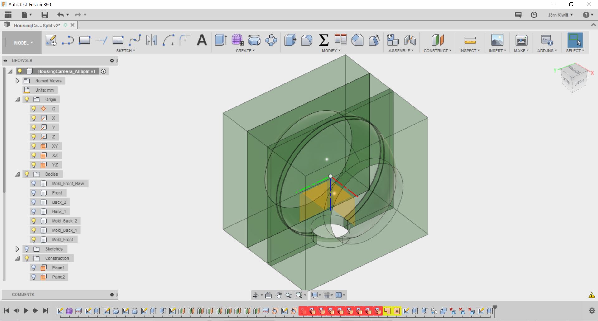
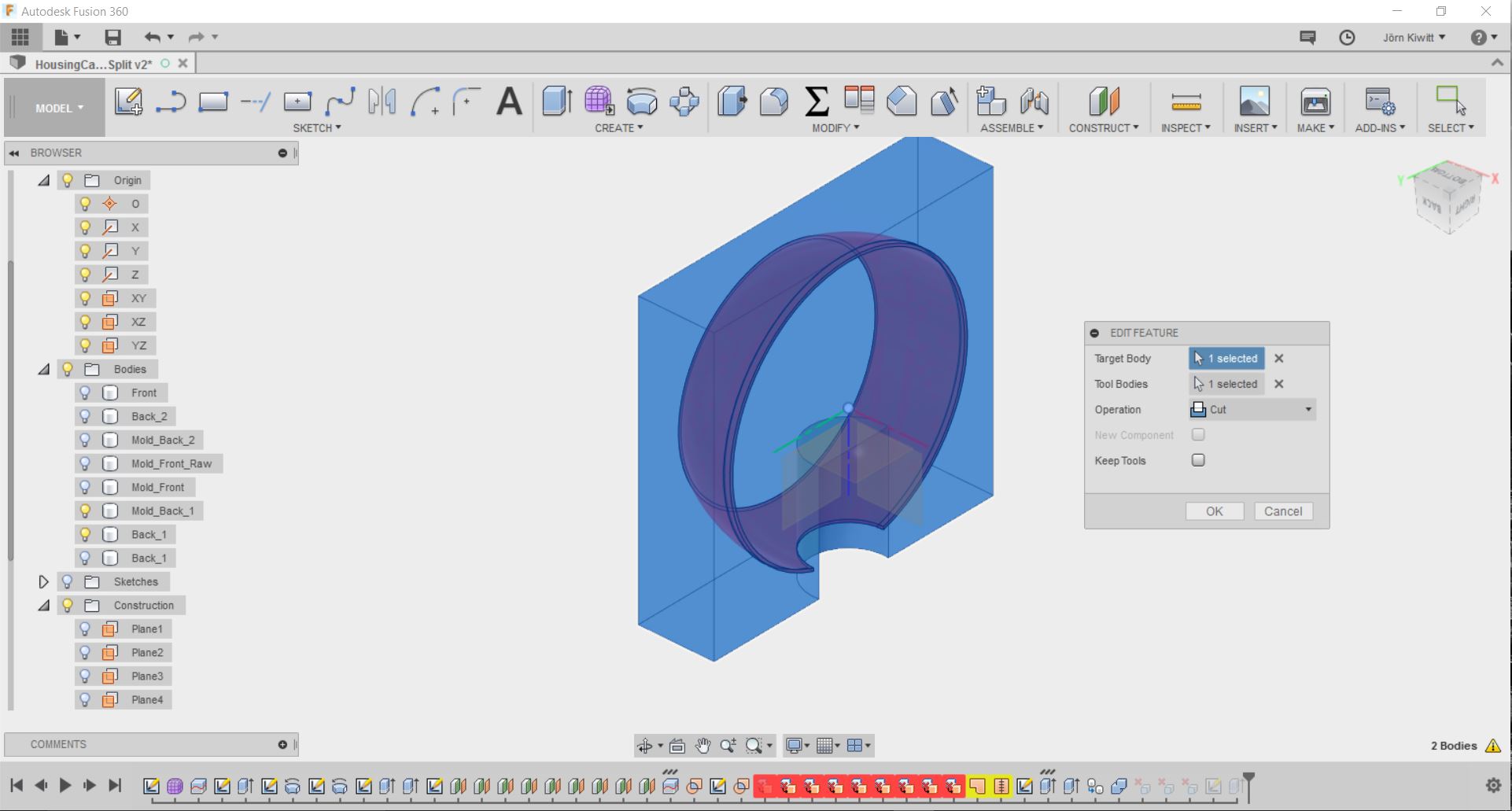
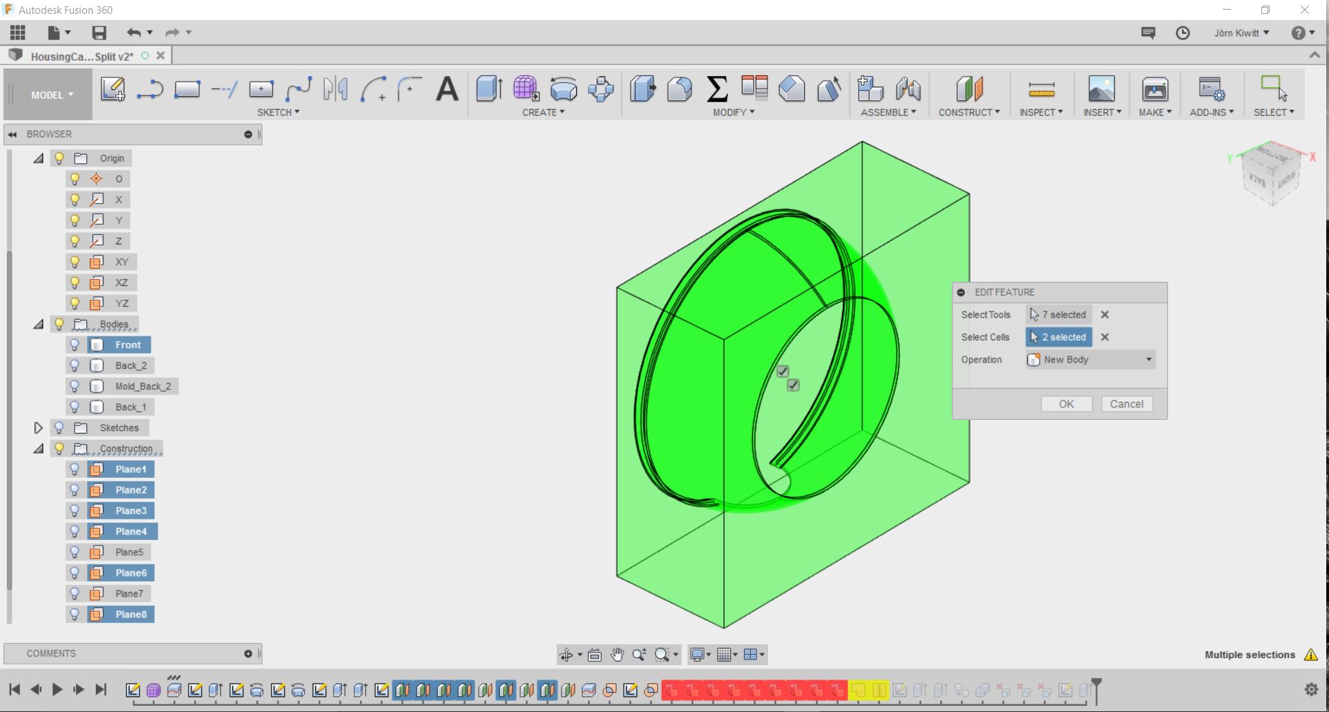
I used the boundary fill function to derive the molds.
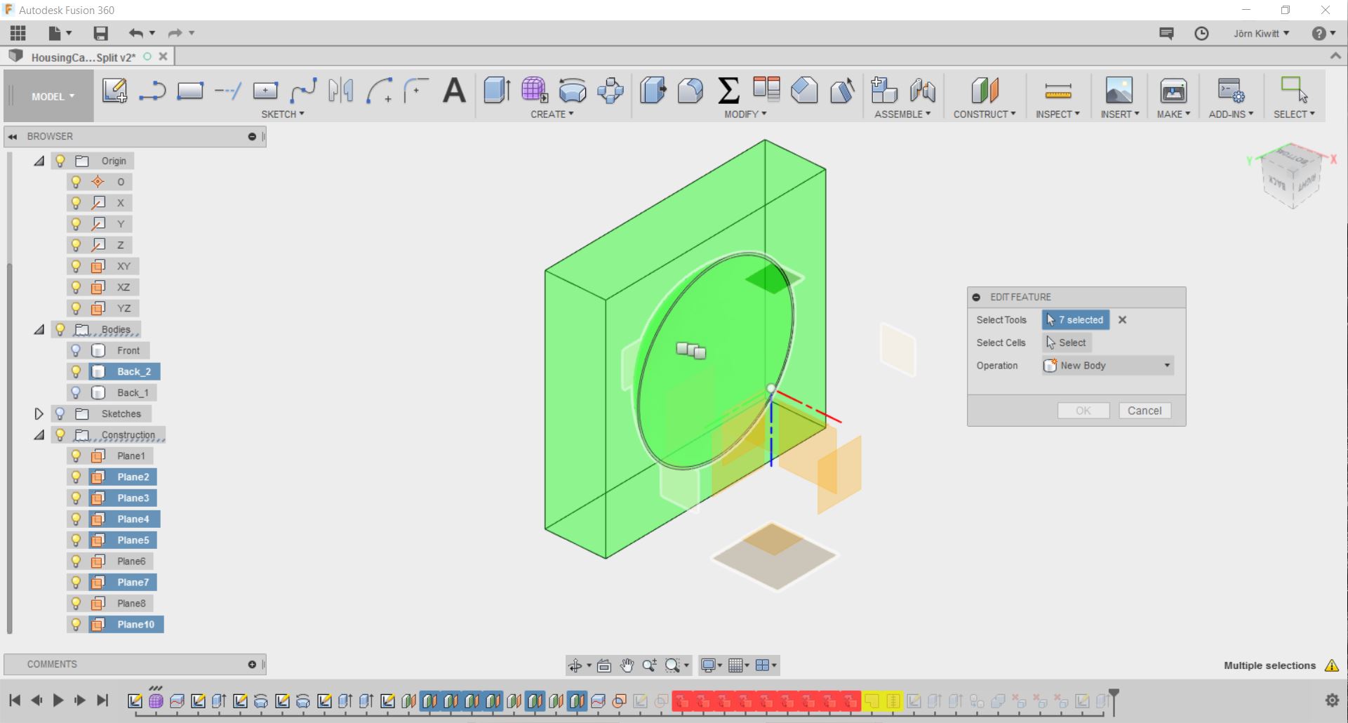
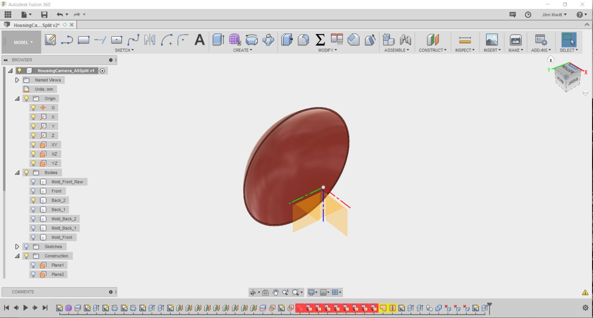
Encountered some problems as boundary fill did not remove all required surfaces so I used the combine function, deleting the remaining surfaces manually.
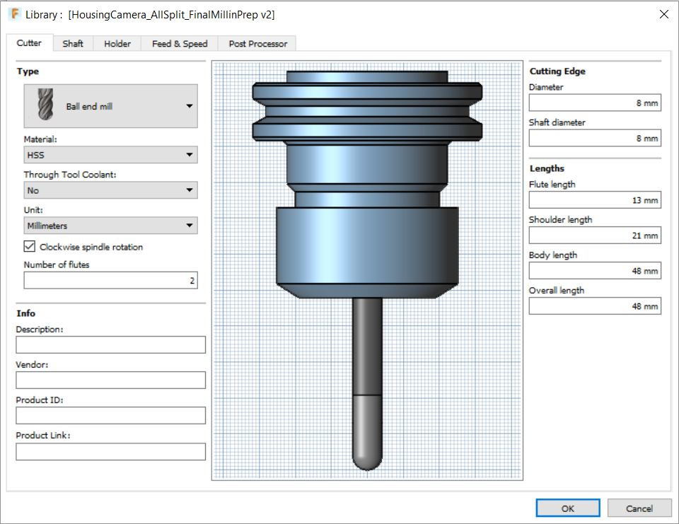
I used two different tool for milling. The Backside 1 mold was done with the ballnose, everything else the flatnose tool.
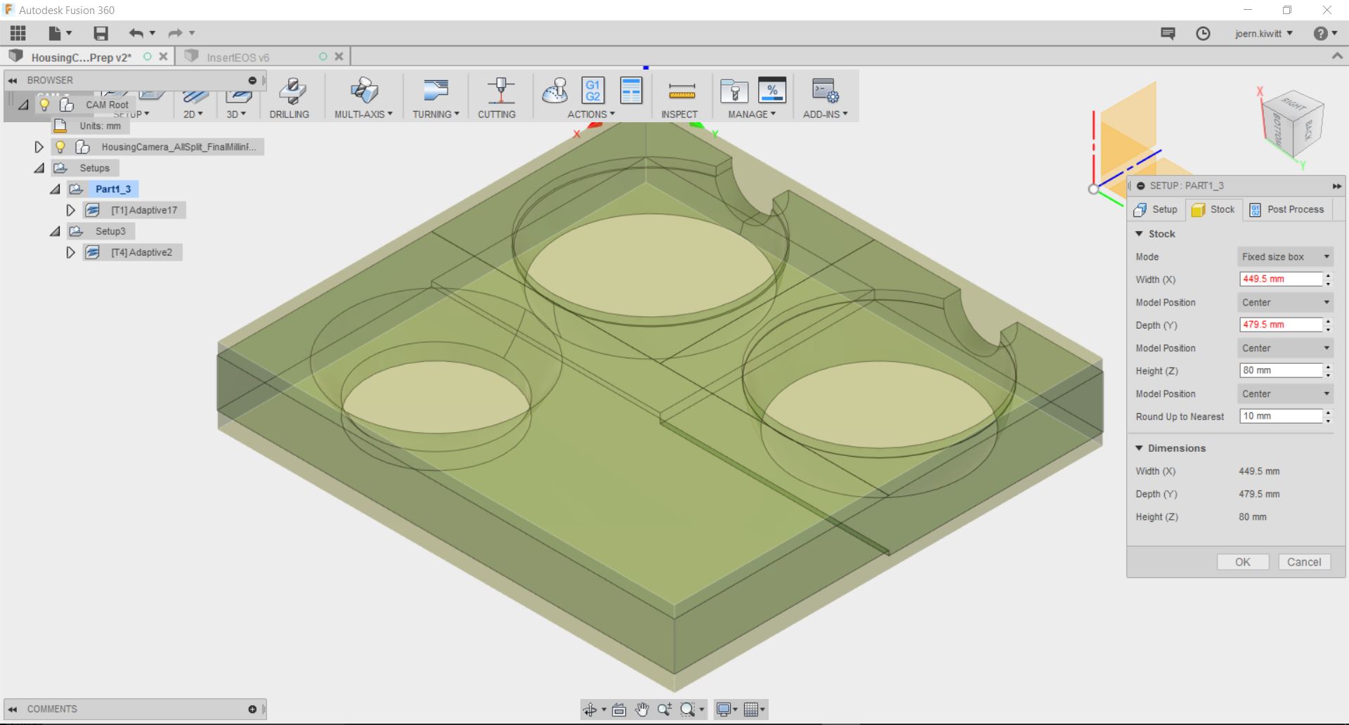
CAM process
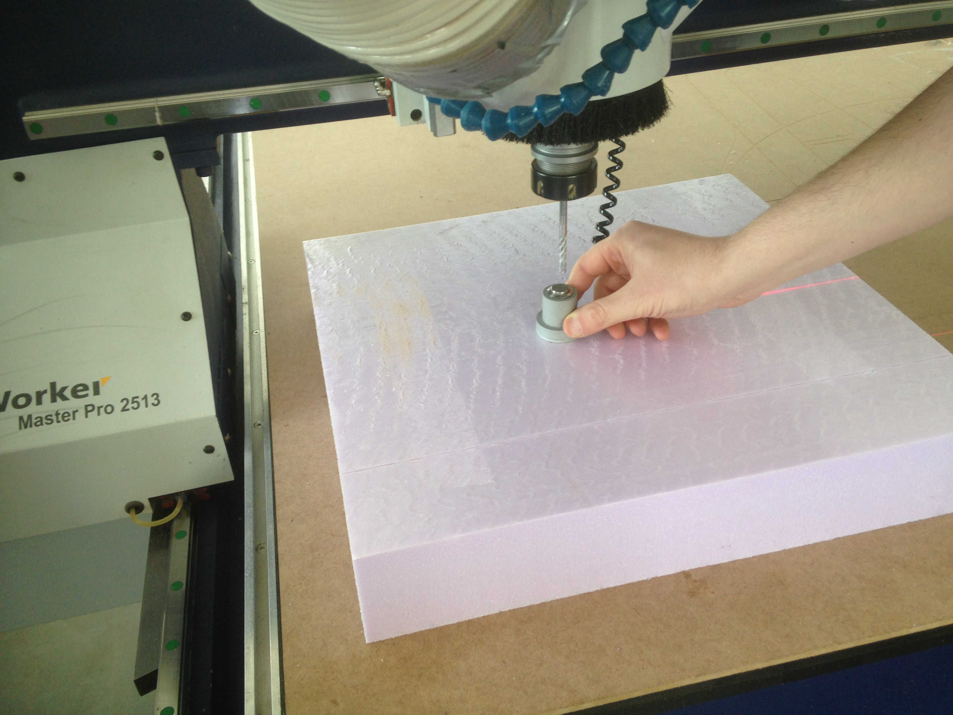
To use the EasyWorker Master Pro 2513 in 2.5D mode, I needed to install the correct CAM processor first, which is a available here. Furthermore, there is a description on how to install this within Fusion 360 that can be found here.
Link to Post processor
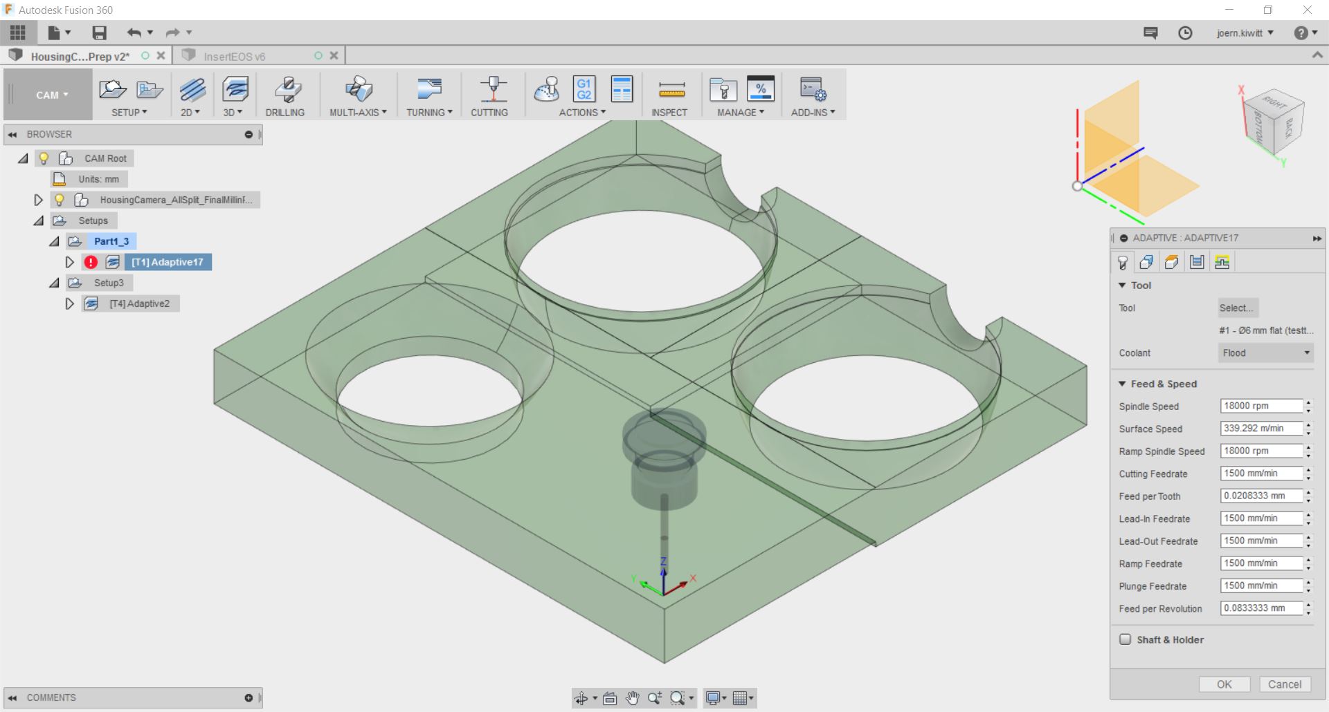
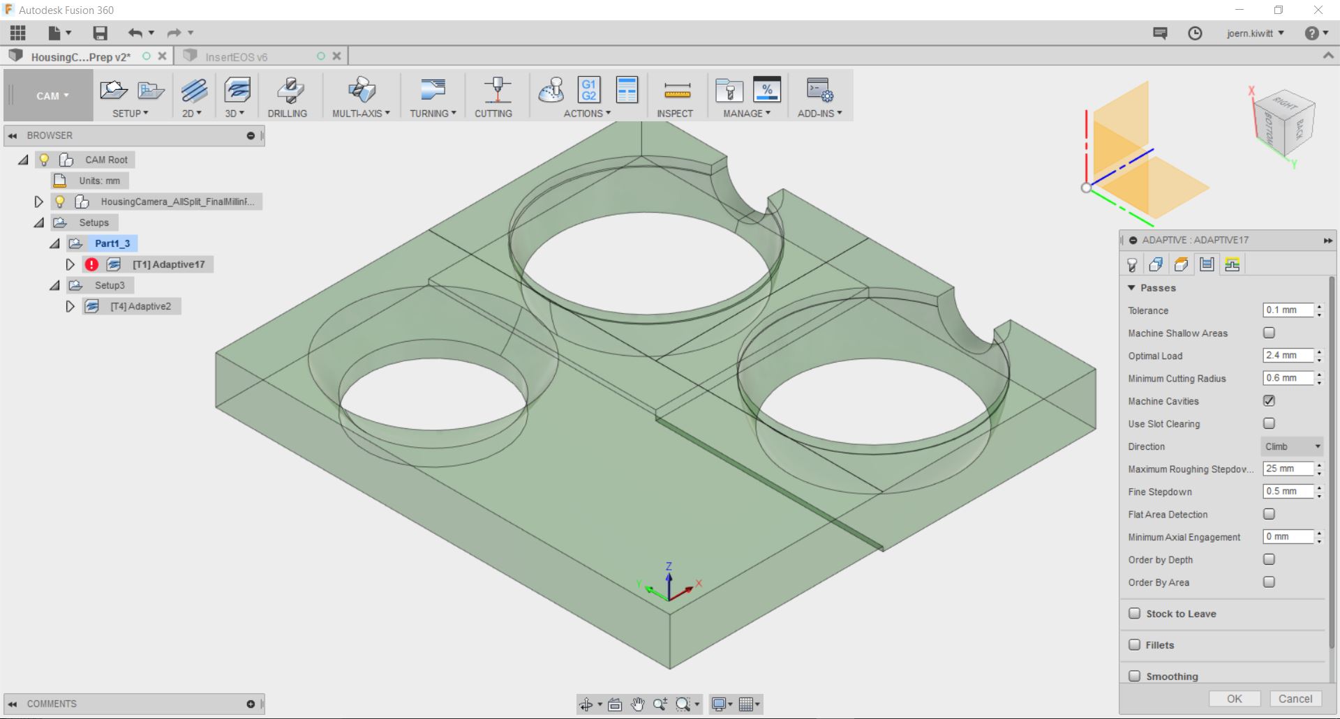
For this I used a flat nose mill.
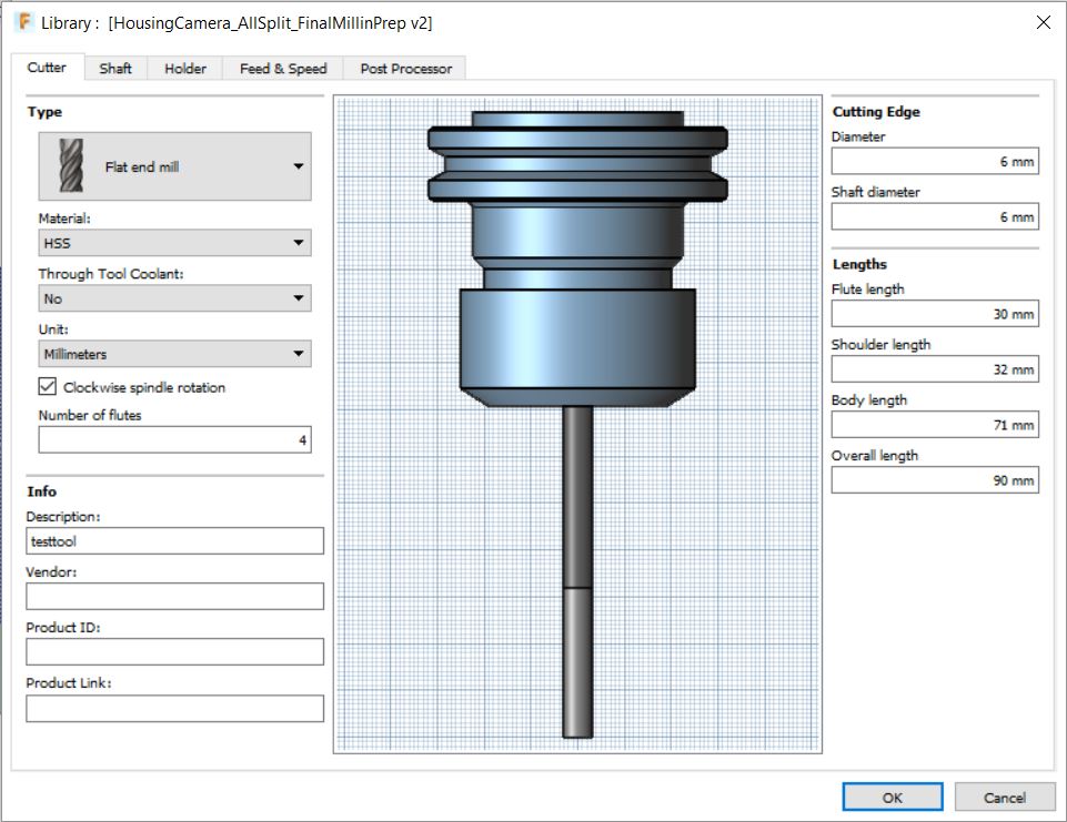
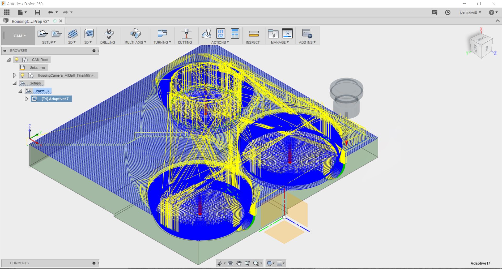
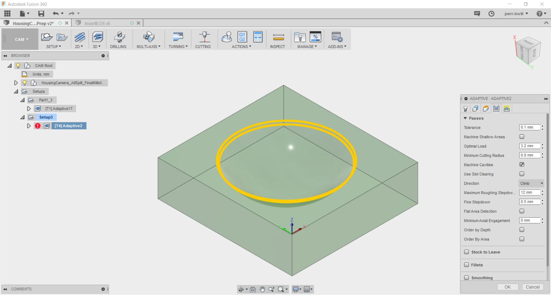
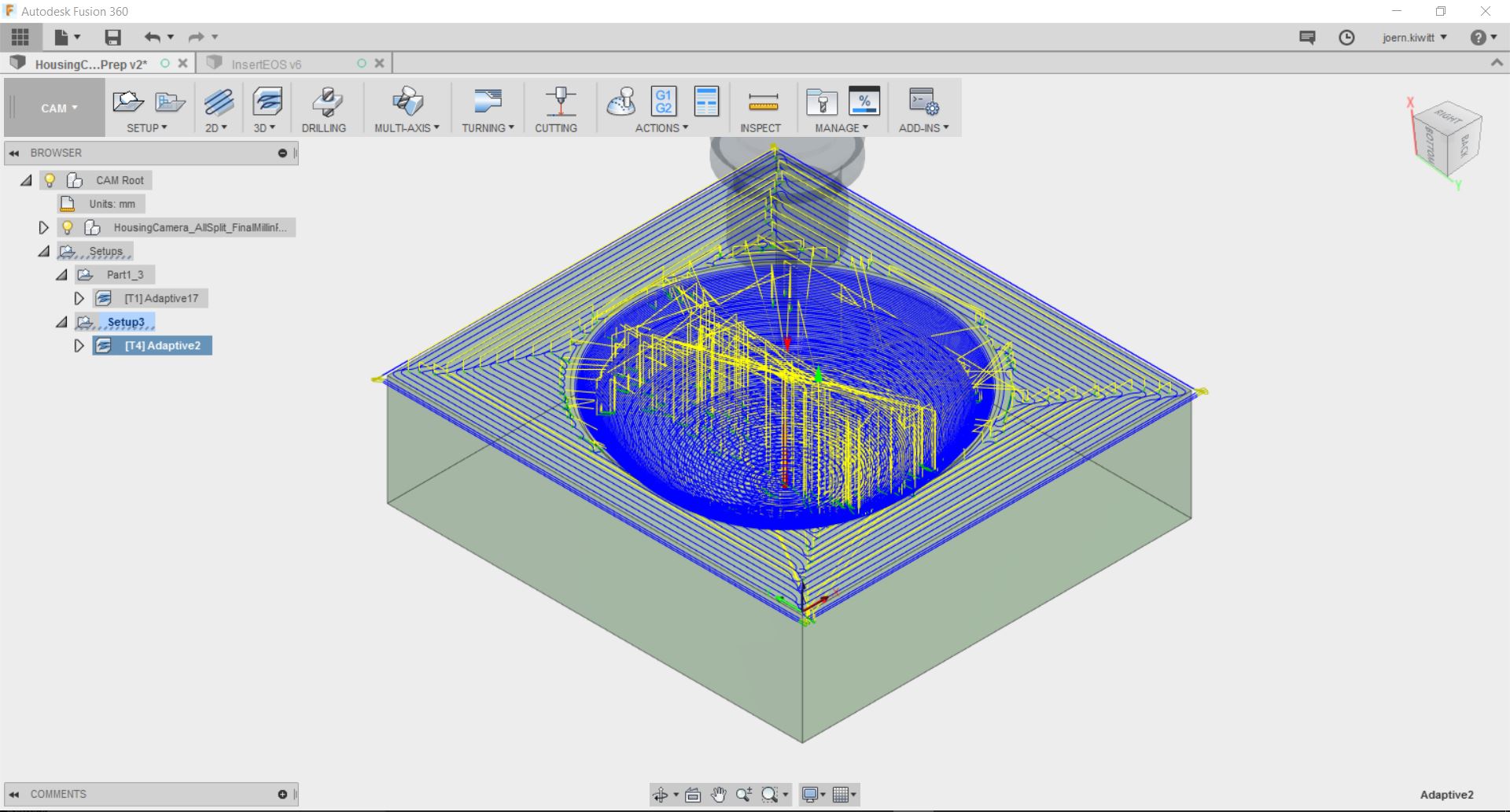
After adding the tools to the library, I started preparing the G-code.
And the second part with the ball nose mill.
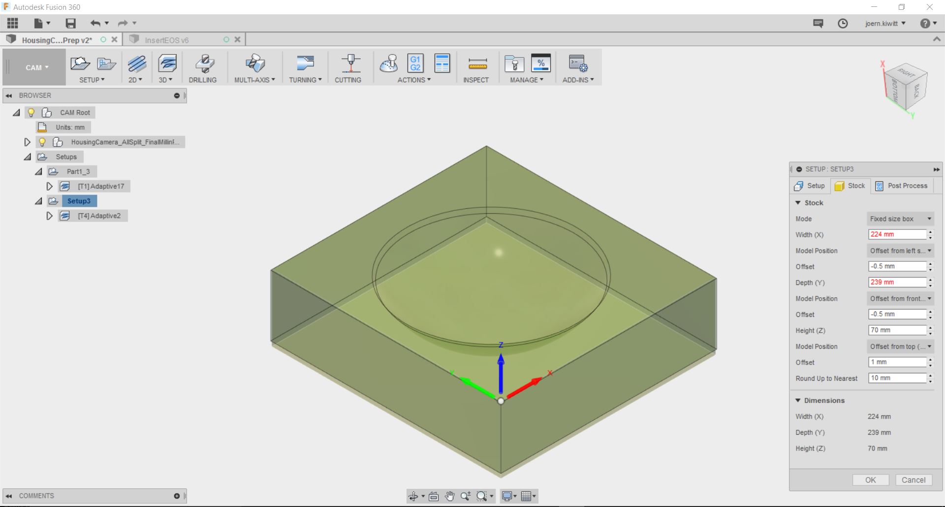
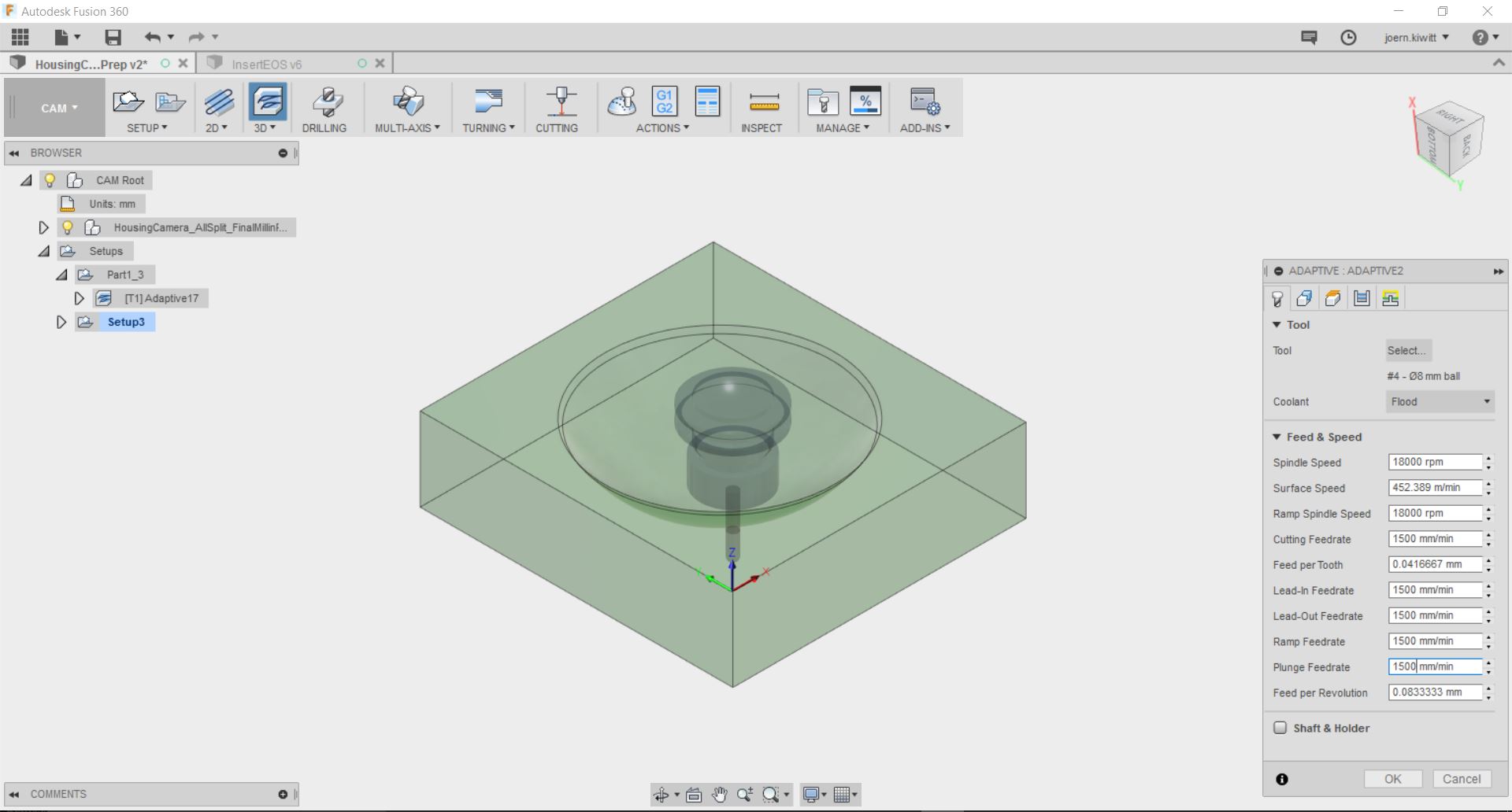
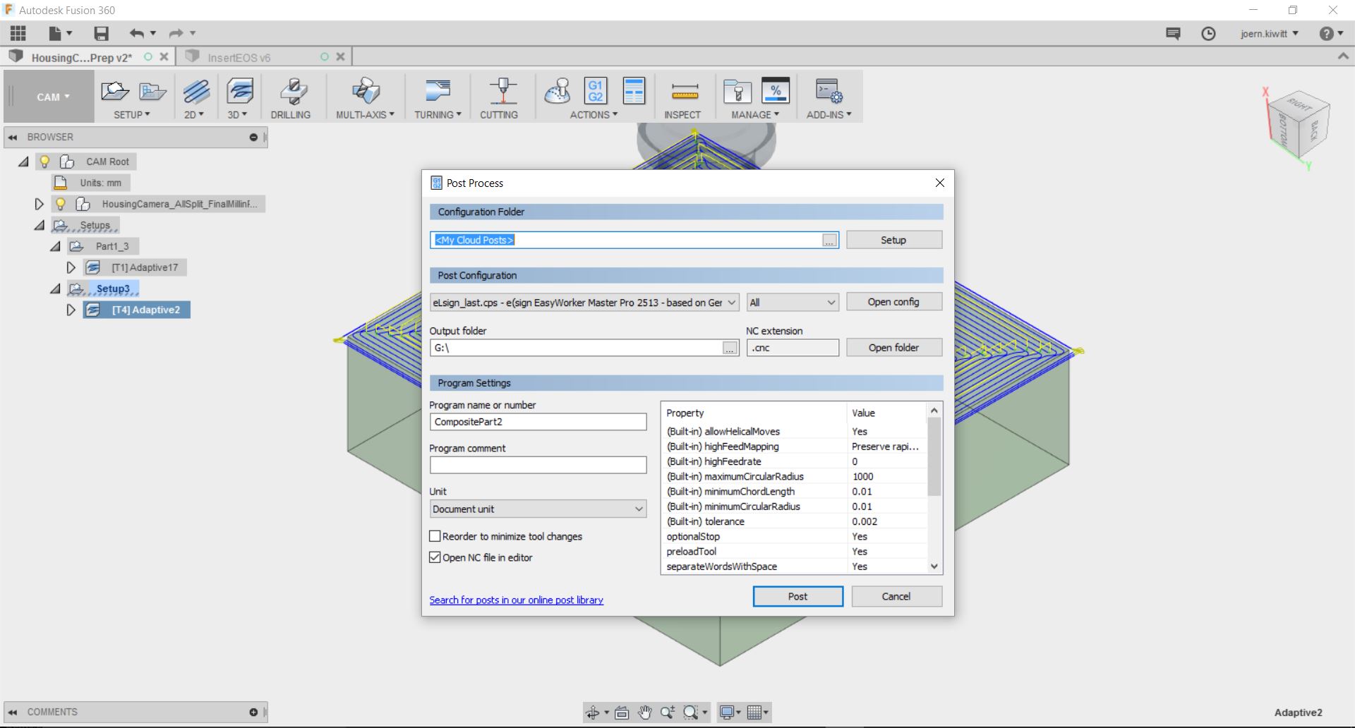
The final step is the post processing which outputs the G-code for the EasyWorker. The tool I used had the number 4 and 1 on the tool changer which had to be put in for the post processor output.
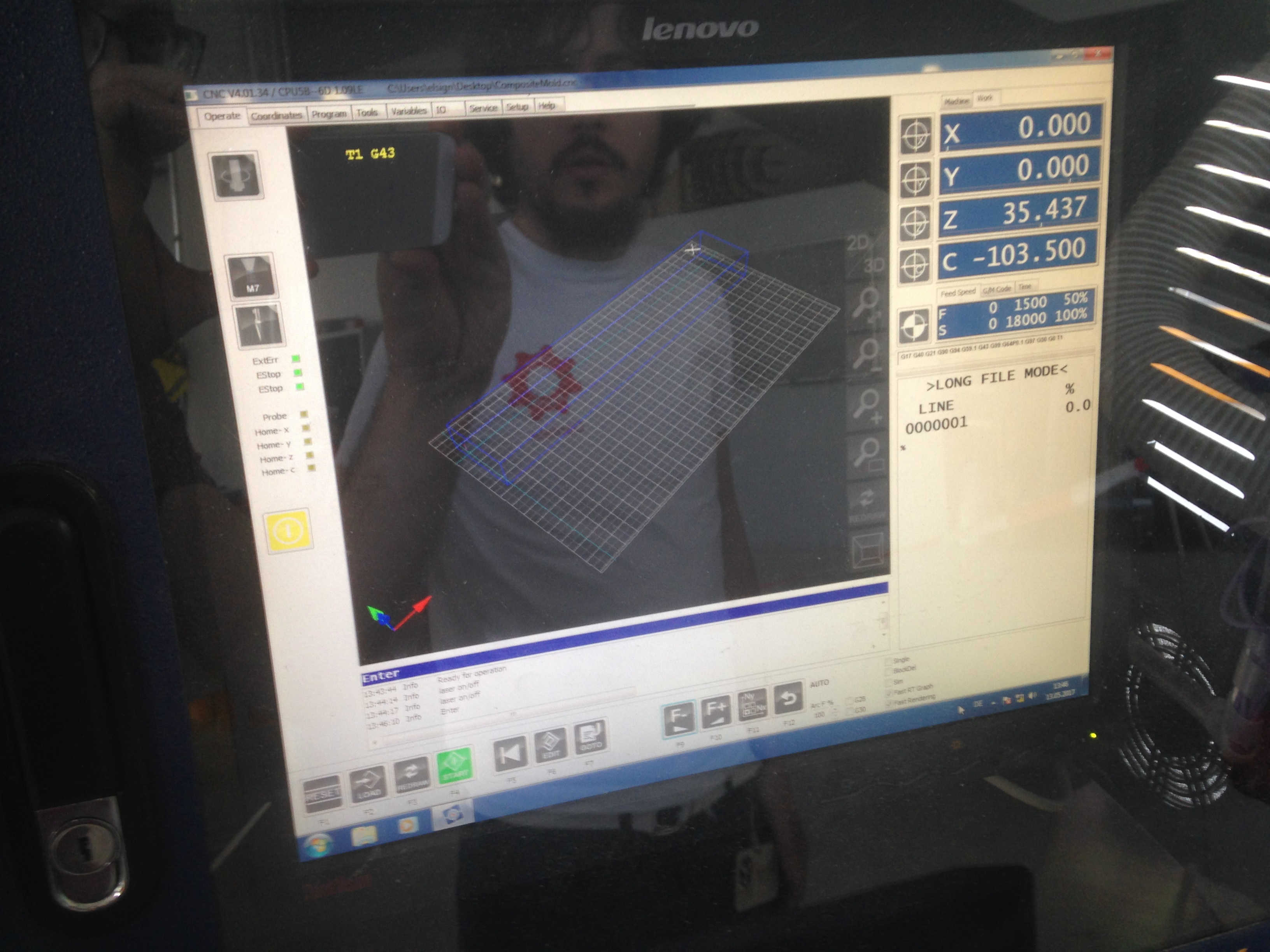
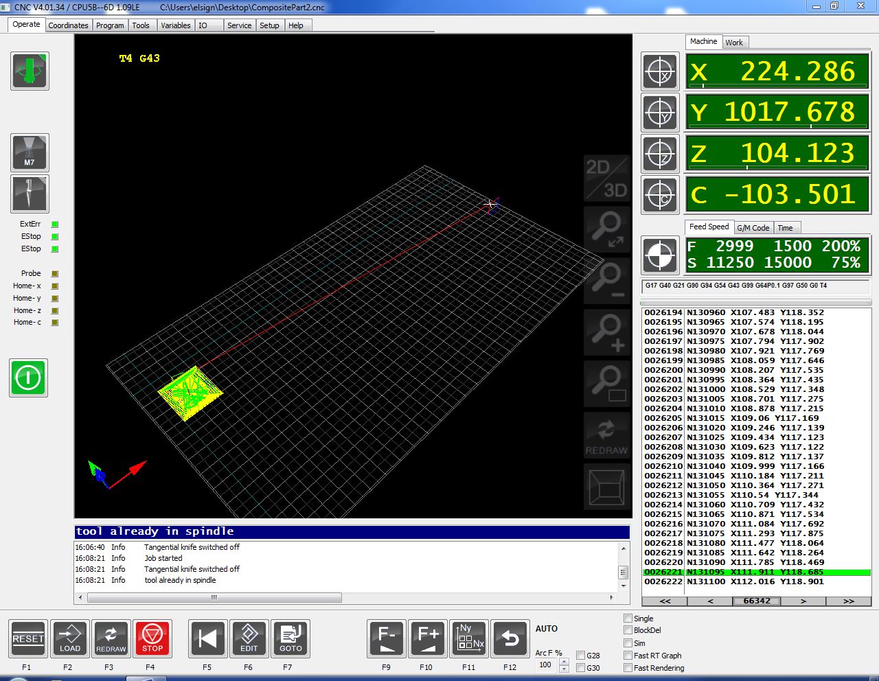
Machine settings
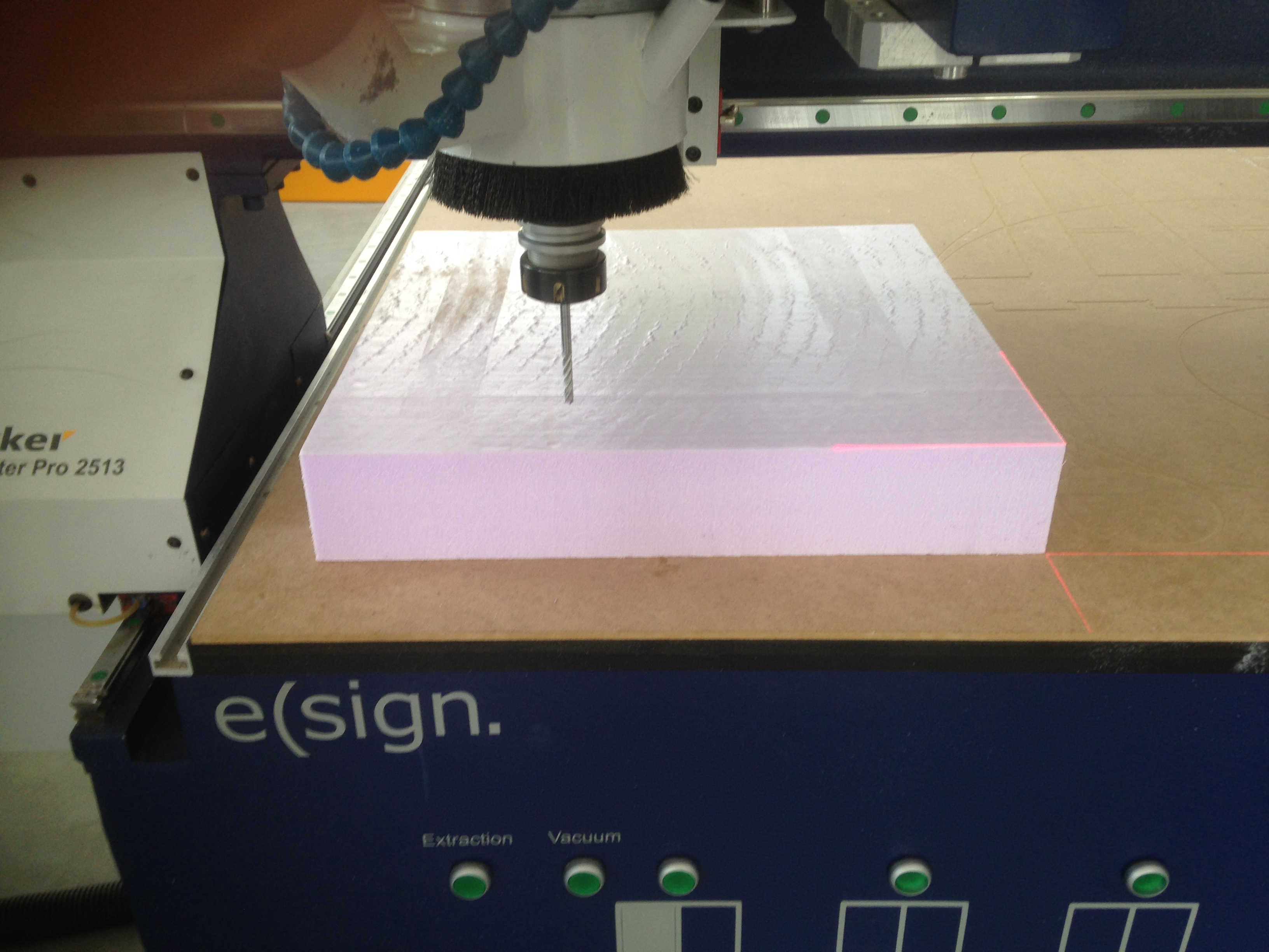
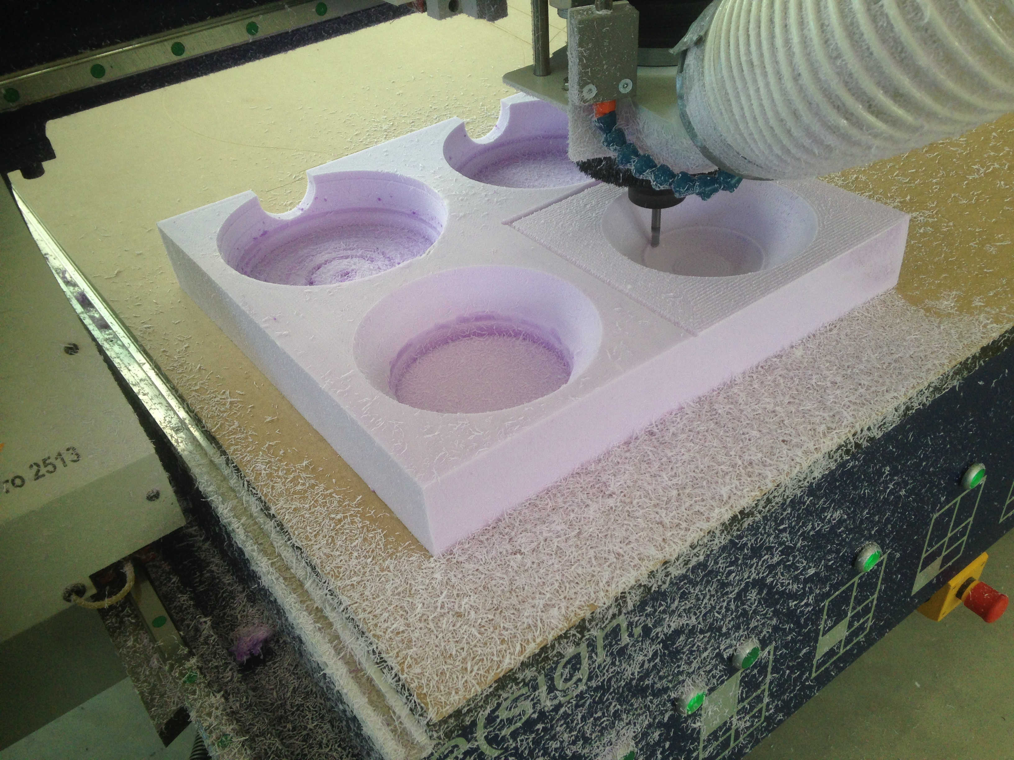
The simulation did not show the toolpath on the machine. I still launched the job and the machine followed the path as calculated.
As I was cutting the foam a bit too fast, it got molten around the tool and damaged the mold surface as a consequence.
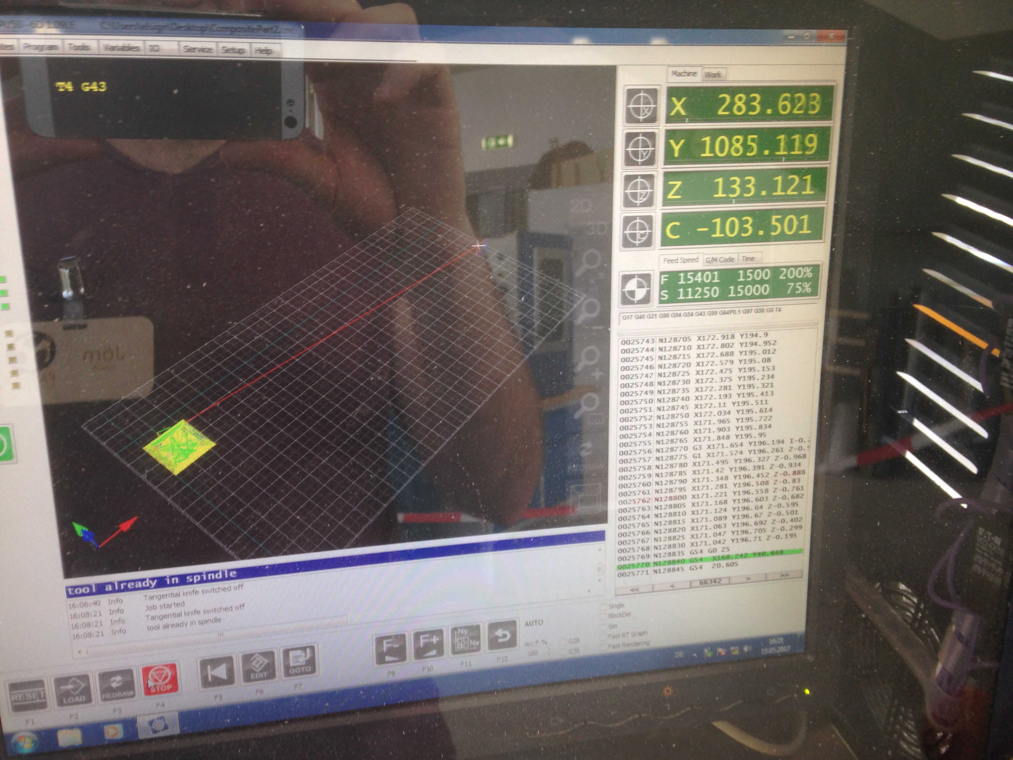
How to stop and start
Stopping, reducing or increasing spindle & cutting speed.
Making composites
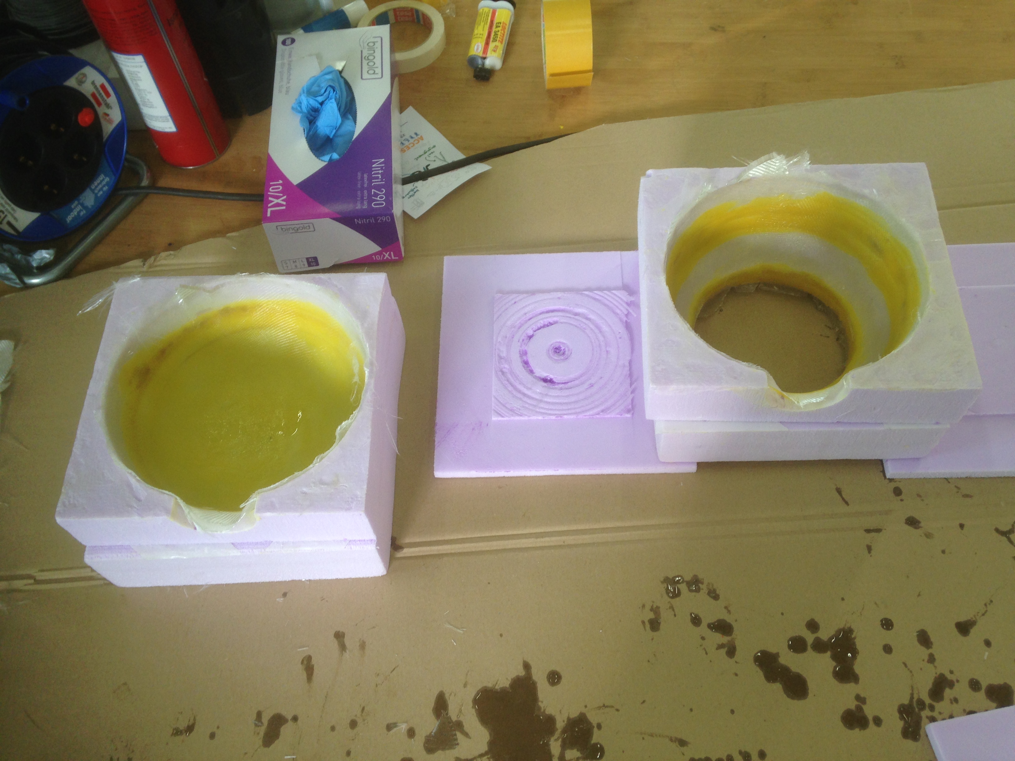
I used a circular saw to cut off the bottom and double-sided tape the glue the two parts on each side together. Furthermore, I used way (yellow) to fix unevenness in the mold. Due to the low melting temperature of this particular wax, it can be easily modelled.
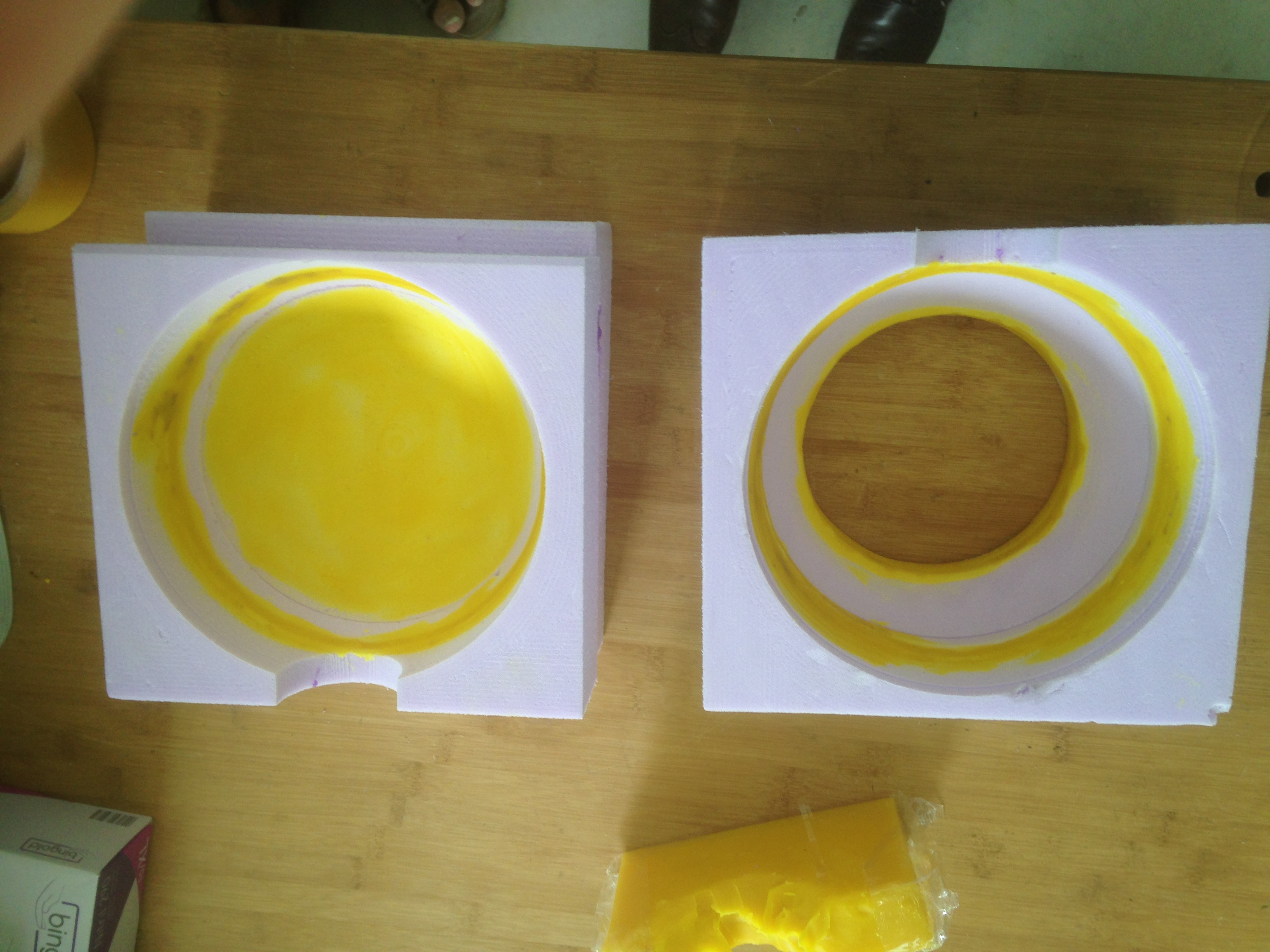
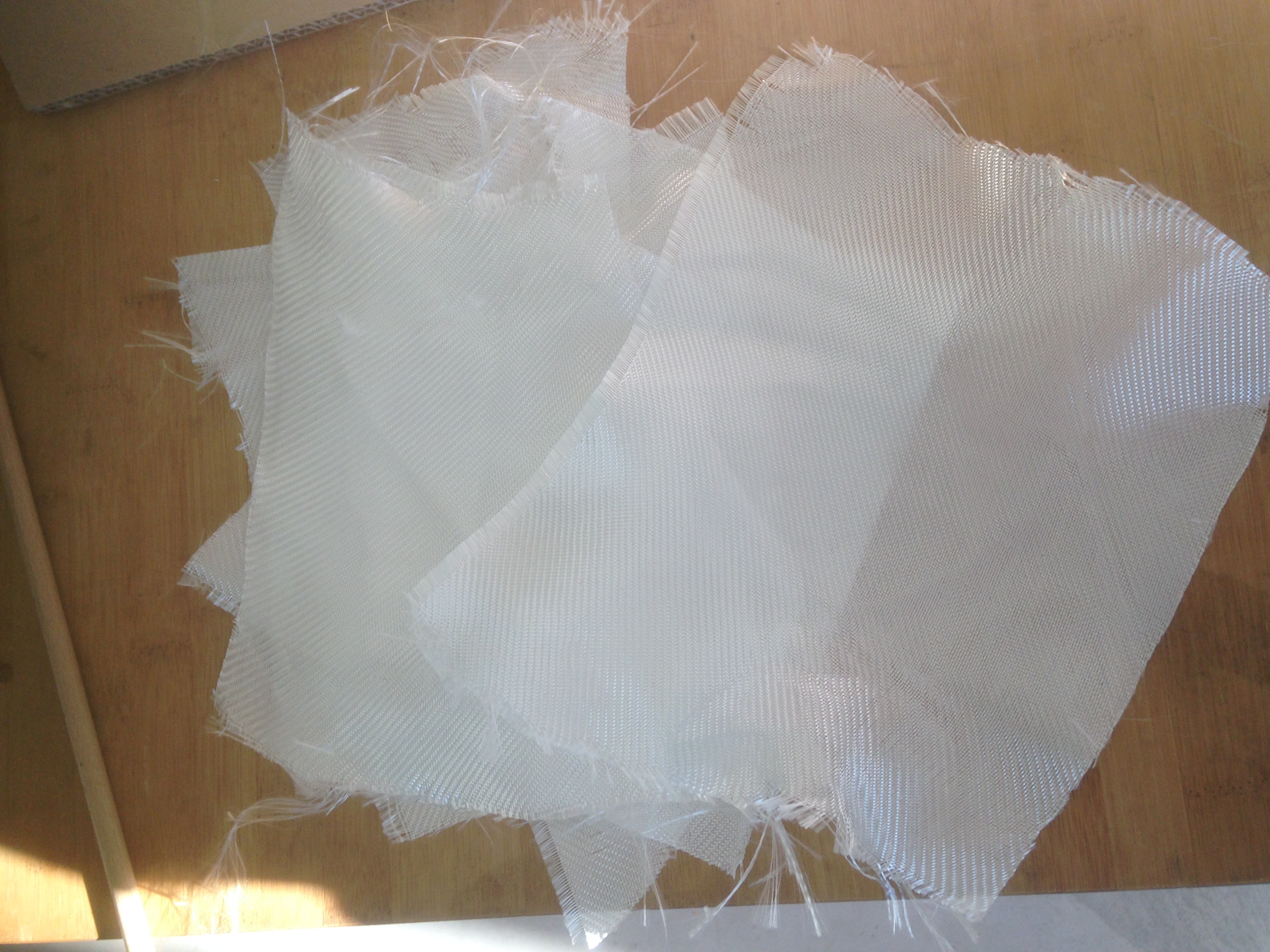
I applied a release agent and cut pieces of glass fiber.
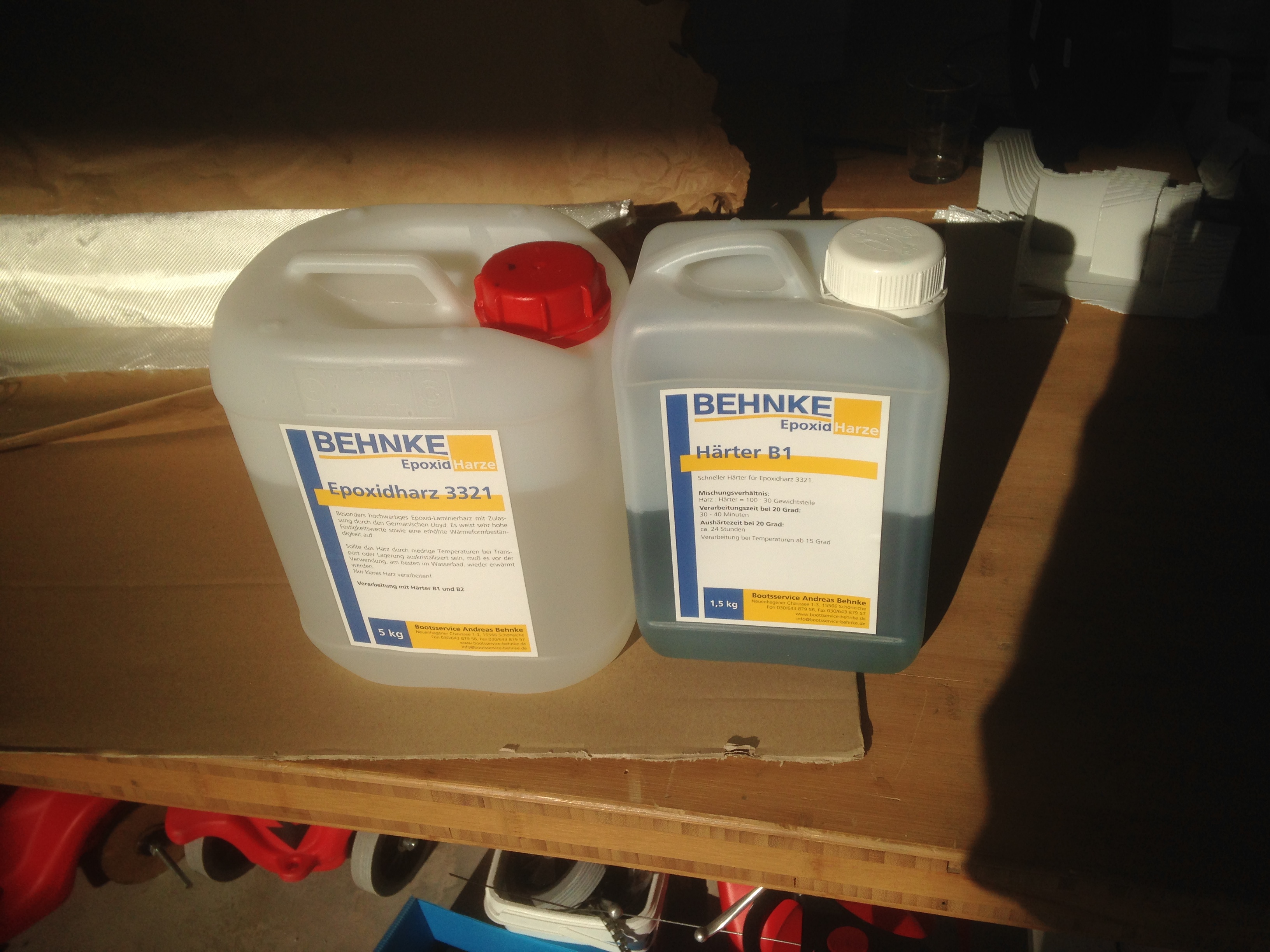
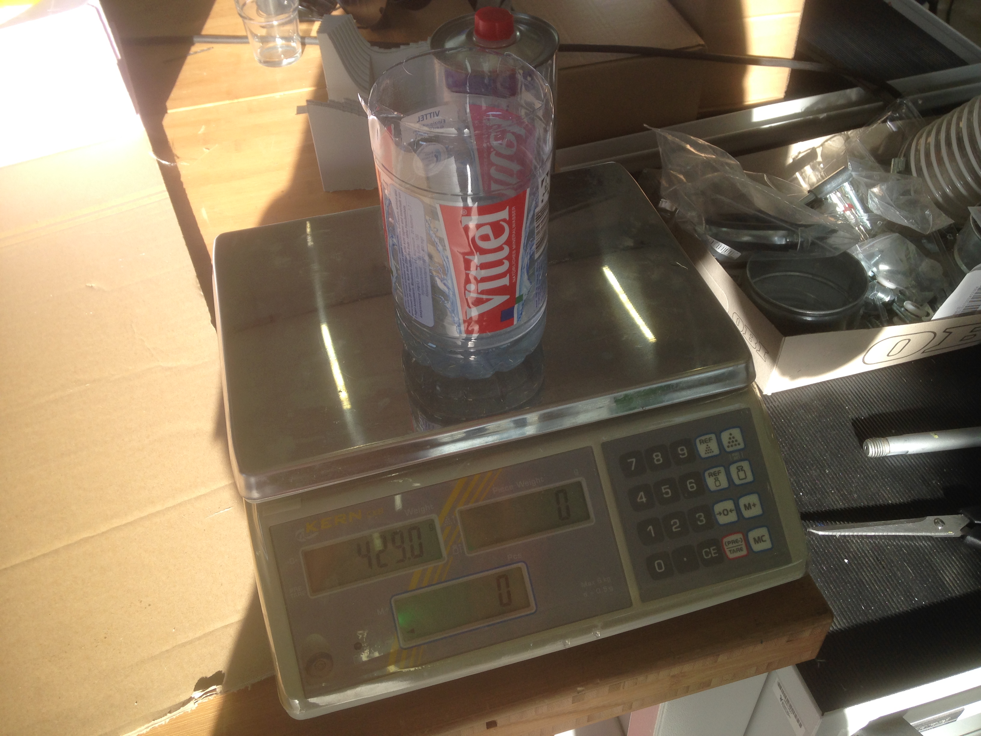
I used the epoxy resin below. Hardener and resin have to mixed in 100:30 ratio by weight. I retrieved information from data sheet. There are different hardeners. The one I used was marked as B1, giving me a pot life of 30 min.
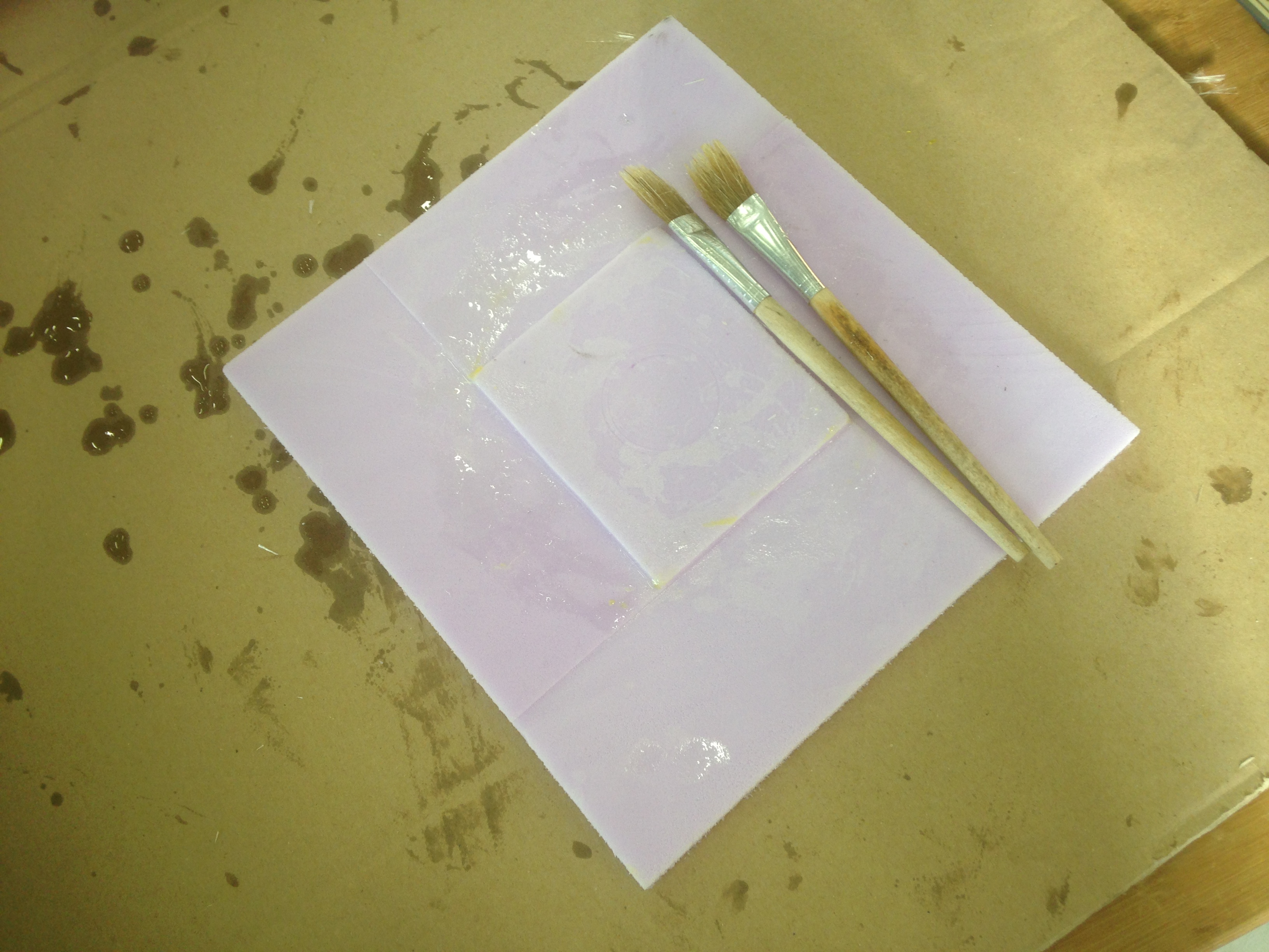
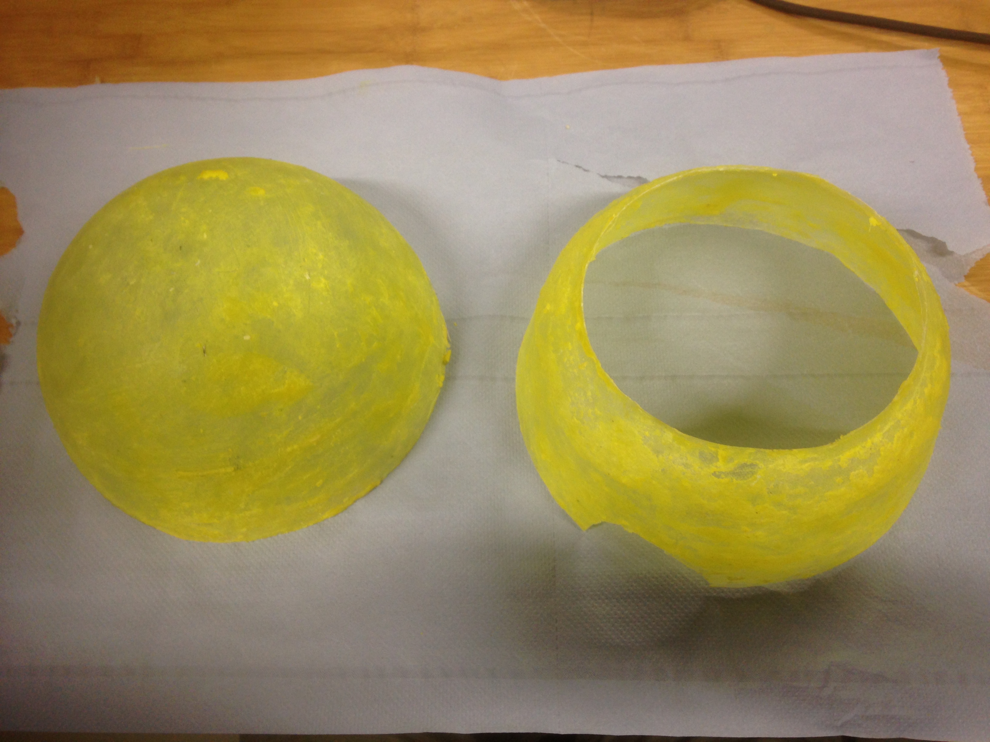
The fibers were impregnated with a painbrush, layer by layer. In this case, I did not use vacuum due to the concave shape of the mold and no need for a high quality result with a distinct fiber volume content.
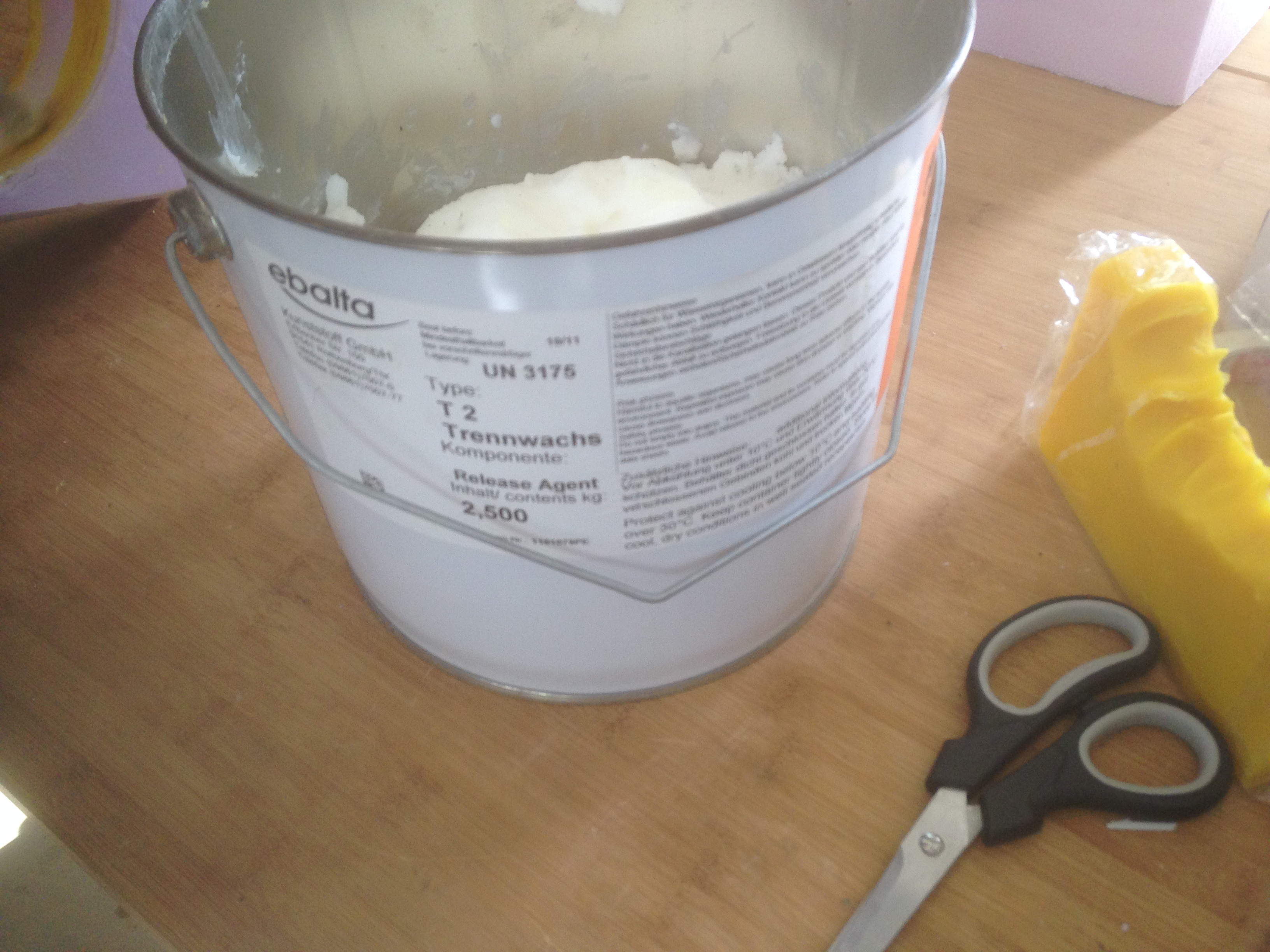
The release agent did not work with the foam, so that the wax came out with the molded parts. Next time, I should probably use aluminum foil in between. However, after several attempts of cleaning with hot water, a heat gun and in an ultrasonic bath the final result looked OK.
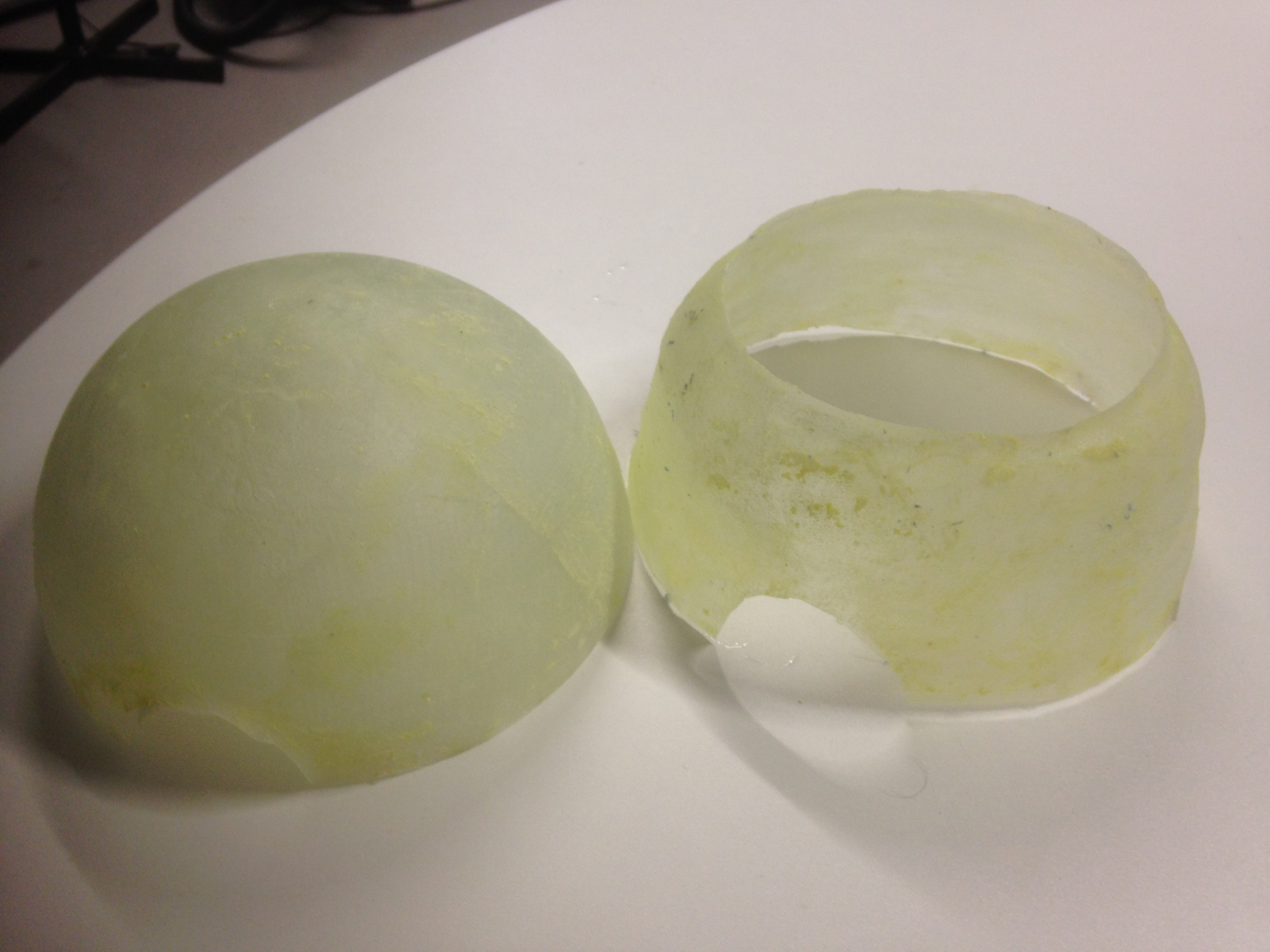
The composites can be ground later on for painting.