Week 05 - 3D scanning & printing
Menu
3D scanning
3D scanning & printing are somehow two sides of the same medallion. 3D scanning takes you from a physical model to a 3D model that can be tweaked using your favourite CAD software. Once your modifications are complete, you can use a 3D printing to go back from bits to atoms.
There are multiple 3D scanning technologies. We will use 3D System's Cubify Sense which works with a similar principle as the popular Microsoft Kinect. Actually, both devices are supplied by the same sensor manufacturer. The scanner uses a camera and a depth sensor to reconstruct a 3D image. This is error-prone due to lighting and reflections. The object you are trying to capture should be isolated from any surrounding objects. Still, some tweaking of the 3D model will be necessary afterwards to get a good result due to artefacts and holes.

The scanner comes with Sense a software that allows capturing of the 3D scans as well as basic tweaking of your scans, such as:
- Crop: cut to size
- Trim: do a line cut
- Erase: delete surface area
- Solidify: repair holes and close geometry
- Color: tweaking brightness and color
The result can then be exported, e. g. as an *.stl or *.obj-file for further manipulation. Blender for instance offers a variety of tools for sculpting. If you are interested to learn how this works, I can only recommend this tutorial on youtube:
Other 3D scanning techniques involve photogrammetry, where a number of images are taken from an object from different angles. With the help of immense image graphical processing power features of on object can later on be recognized on different images which allows a reconstruction of an object as a 3D model. This technique has become very popular with the arrrival of drone-based remote sensing operations.
Structured light is another way of digitizing a 3D object, which I saw in the automotive industry in wind tunnel experiments in order to measure the reference surface area for the drag coefficient. The lighting conditions are absolutely decisive.
3D Printing
With the arrival of affordable 3D printers, additive manufacturing has made its way into mainstream. Especially, FDM - fused deposition modeling printers from Ultimaker and Makerbot have become a very much accessible technology. Still, there are huge difference between the individual technologies from stereolithografie (SLA), FDM, selective laser sintering (SLS) and binder jetting. The Fablab in Kamp Lintfort is equipped with a bunch of Ultimaker 2, Ultimaker 2+, SLA Formlabs printers as well as with a professional - and rather expensive printer - from 3D Systems and last but not least with a BigRep. The BigRep is an FDM printer with a build space of 1 m by 1 m to enables - as the name implies - to make rather big objects.
Please find a short introduction to some prominent additive manufacturing techniques in the videos below.
Sterolithography (SLA)
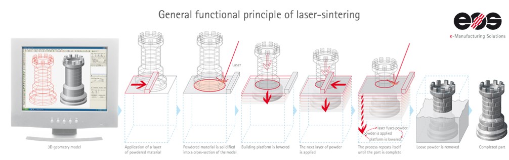
Selective laser sintering (SLS)
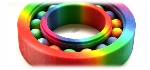
Powder printing (3DP)
FDM - Fused deposition modeling
For this exercise I will focus on the FDM technology. Hopefully, I will have the opportunity to also print on the Formlabs printer at a later stage. In the SLA process a light sensitive resin is cured during the printing process.
Tasks for the week 05:
- 3D scan an object (and optionally print it) (extra credit: make your own scanner)
- 3D design and 3D print an object (small, few cm) that could not be made subtractively
- group project: test the design rules for your printer(s)
First 3D scan
Scanning myself
The first scan turned out to be of terrible quality. Especially, the closing of the loop after going a full round with the scanner was not working properly.
Before the scan is started, the object size needs to be selected (small, medium, large) as well as the type of object that can be a person or... something else on your computer. The Sense scanner needs to be connected via USB and will show a green bounding box around the object on the live image, once it is recognized. It is important to maintain an even distance while turning the scanned object (or scanner the around the object) in order not to 'lose' it. After a full 360 degrees circle one needs to capture also the top and the bottom of the object to close the remaining holes.
In my case, the scanning process did not seem very robust. I tried a couple of times turning on a chair having a fellow student doing the scanning. We played with lower lighting, turning the scanner, turning the object but results remained of low quality. It turned out that smaller objects are easier to scan if you are not in full control of your environment, especially if it comes to lighting.
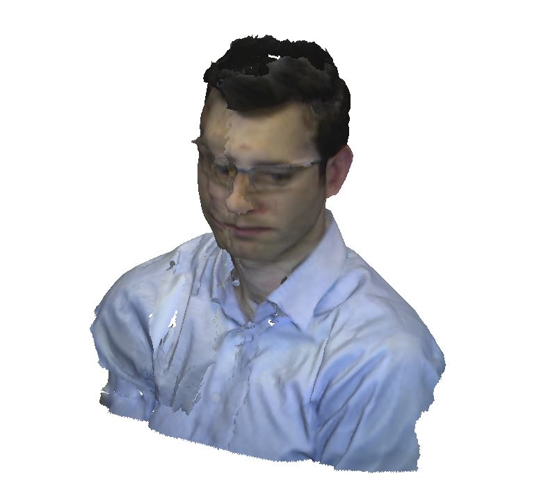
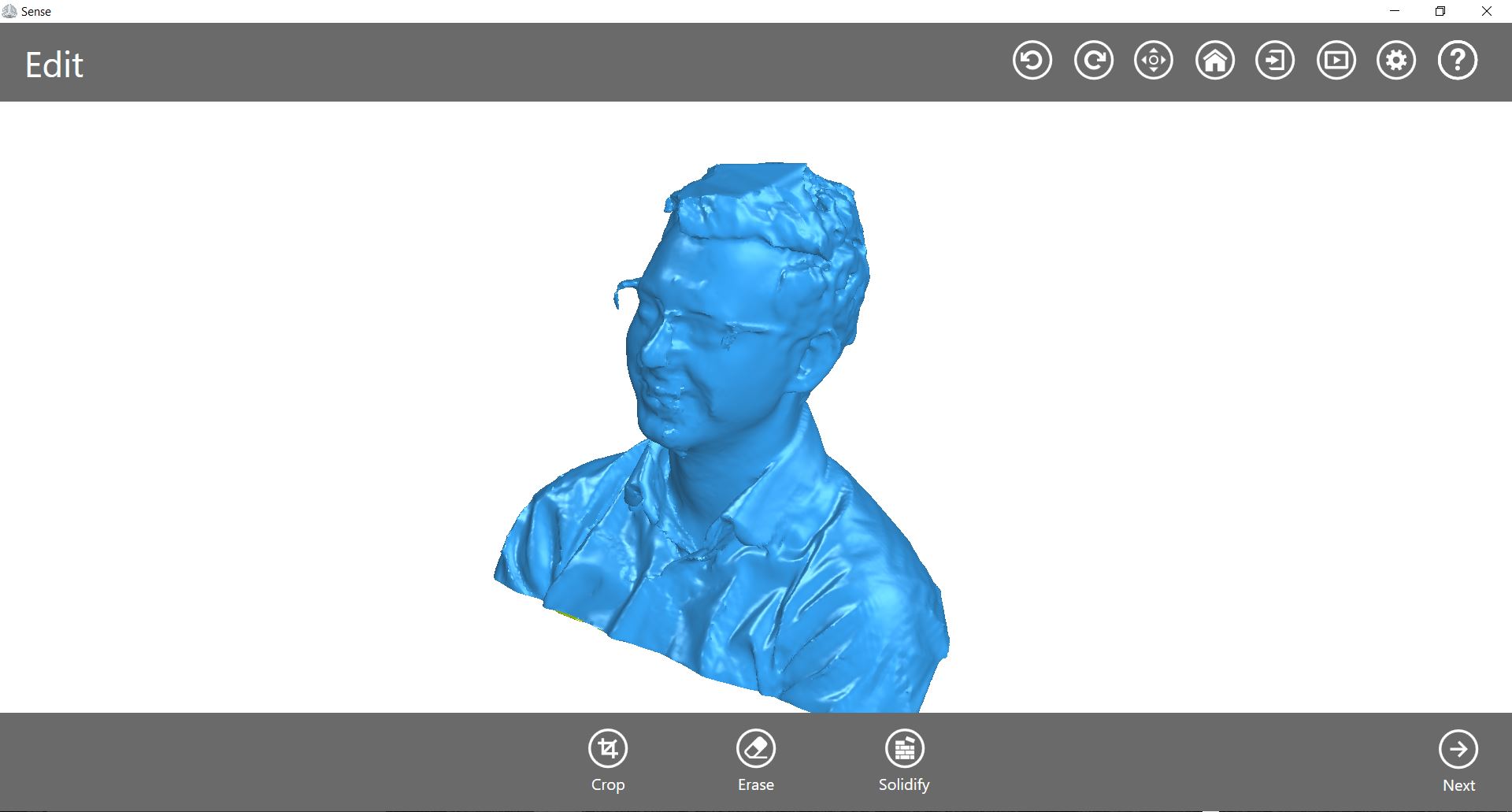
After some sequences of scanning, I decided the quality to be good enough to move on. My glasses however, seemed to be difficult. Maybe reflections from the lenses caused some of the artefacts which disturbed the face reconstruction. If I were to make another trial, I would rather take the glasses off.
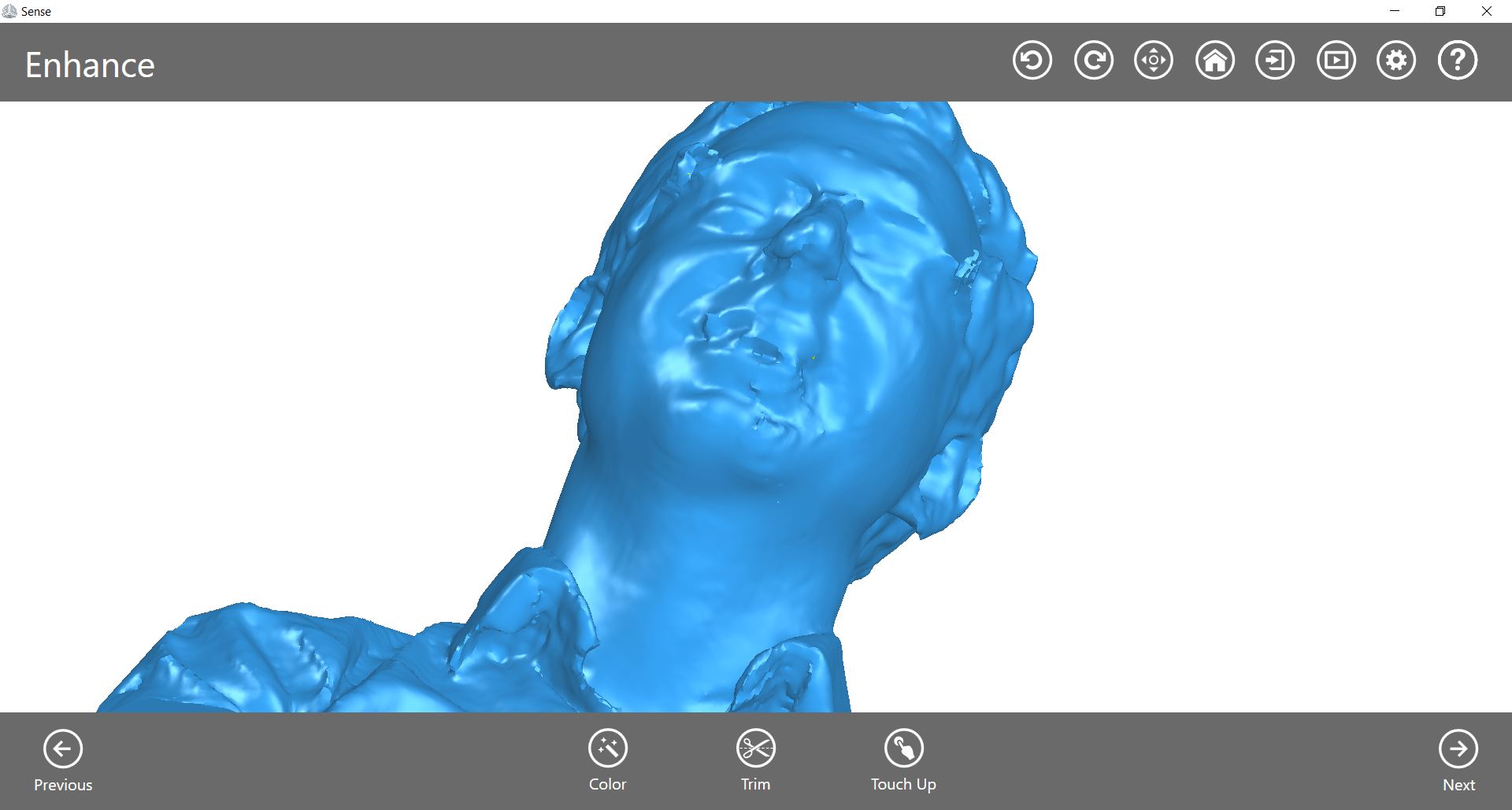
After the scan was completed, I used the built-in post processing tools of Sense, I referred to in the introduction. I used solidify to close the holes in my scan.
I used the touch up function to fix irregular geometries and artefacts and to smoothed of the surface.
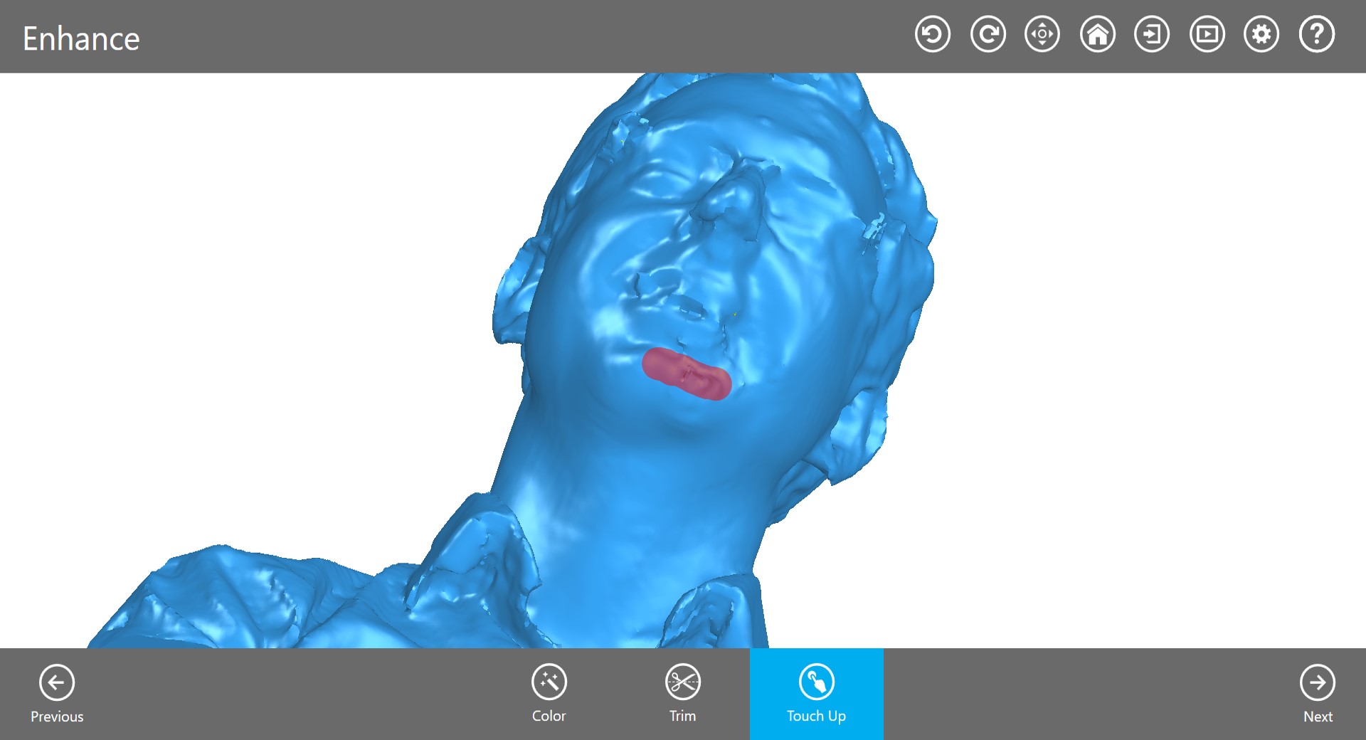

The finished result looks like this. To make a 3D print from this, some tweaking would still be needed, either in Meshmixer or Blender.
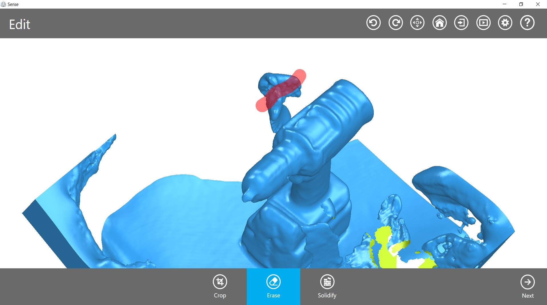
Scan of a powertool
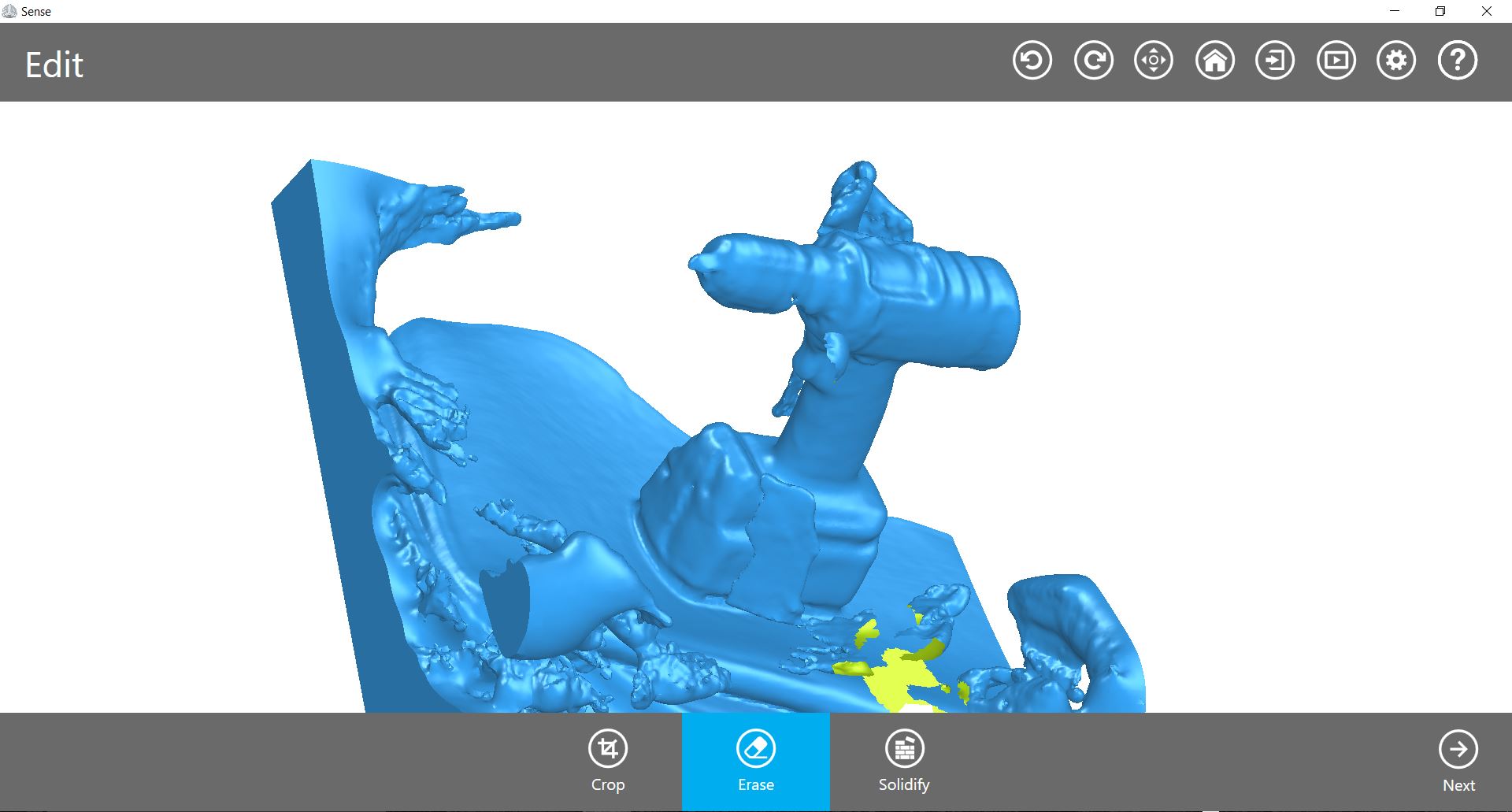
As I was not really pleased with the scanning results, I also tried a smaller object, I could easily scan myself - an electric drill. This however, took some more tweaking and erasing as the scanner detect the surface of the chair, I used as a base as well as some random artefacts. After that, the object was solidified again and some touch up actions were performed.
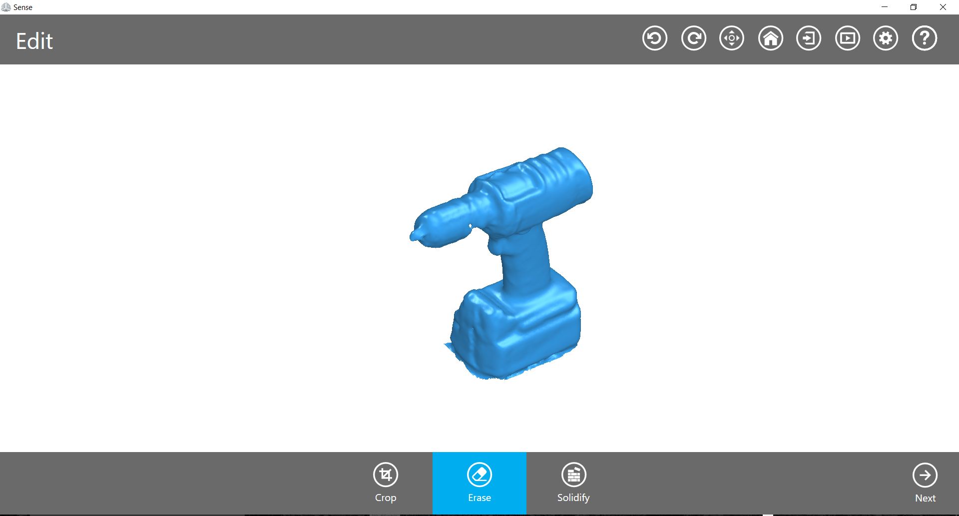
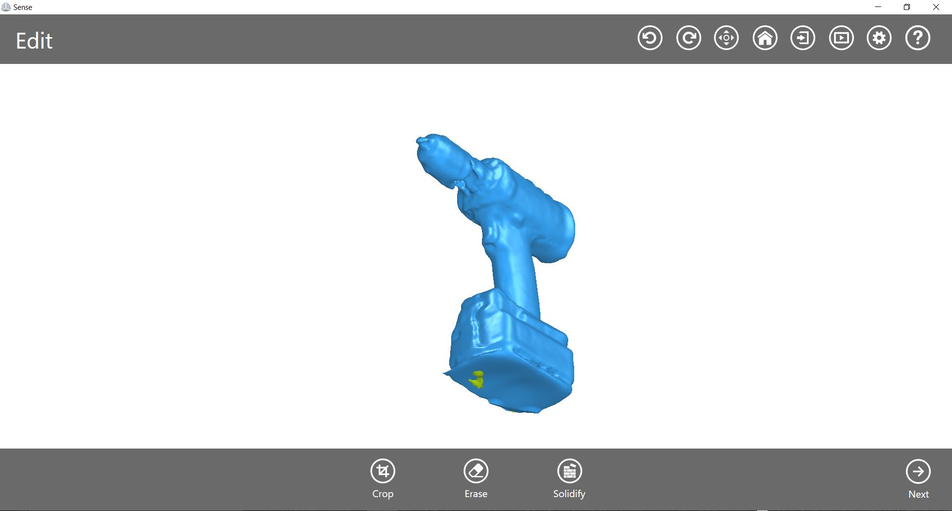
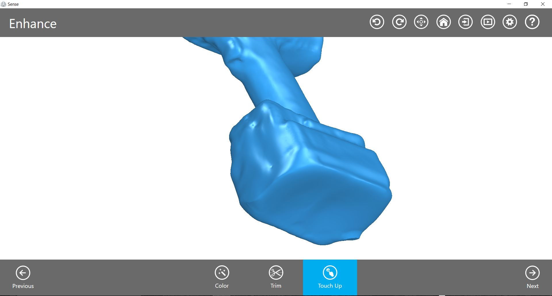
The finished result looks like this.
3D printed part
Design
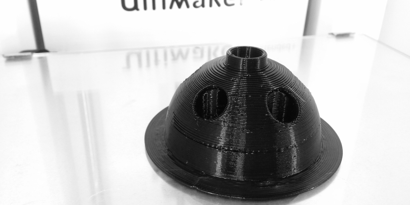
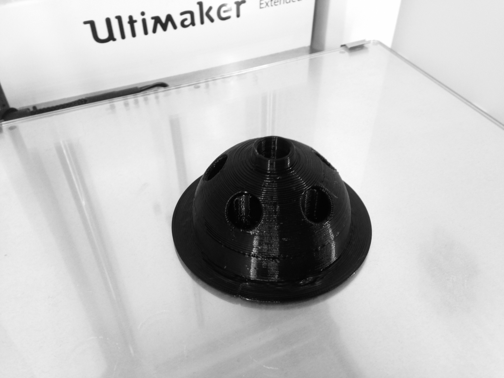
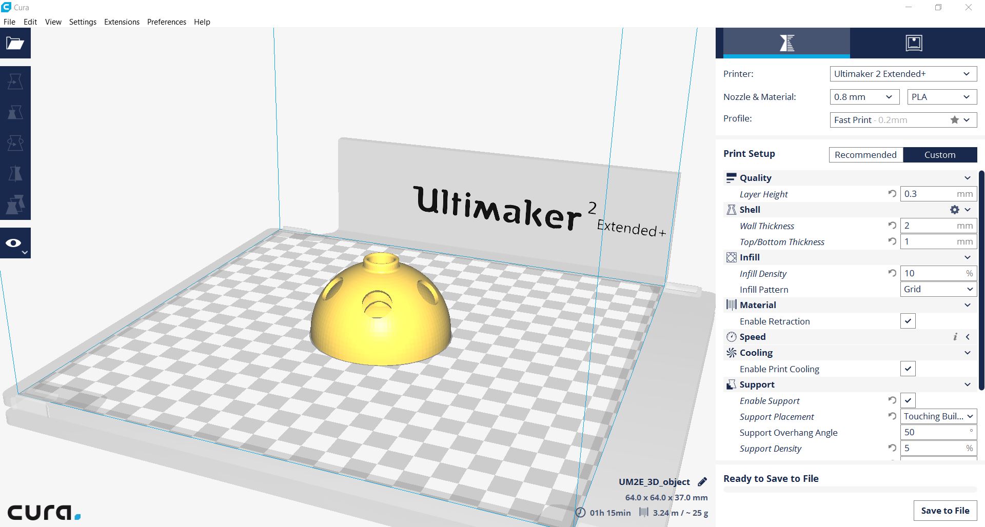
For 3D printing, I designed a small pen holder that is basically a semi-sphere in a semi-sphere which cannot be manufactured applying classical methods. I used Cura for slicing which is an easy to use CAM software by Ultimaker to translate an *.stl-file into machine readable gcode. The code is printer specific. In my case, I used an Ultimaker 2 Extended+ which has some additional build space for taler objects. It is equipped with 0.8 mm extruder nozzle. The printed material will be PLA.
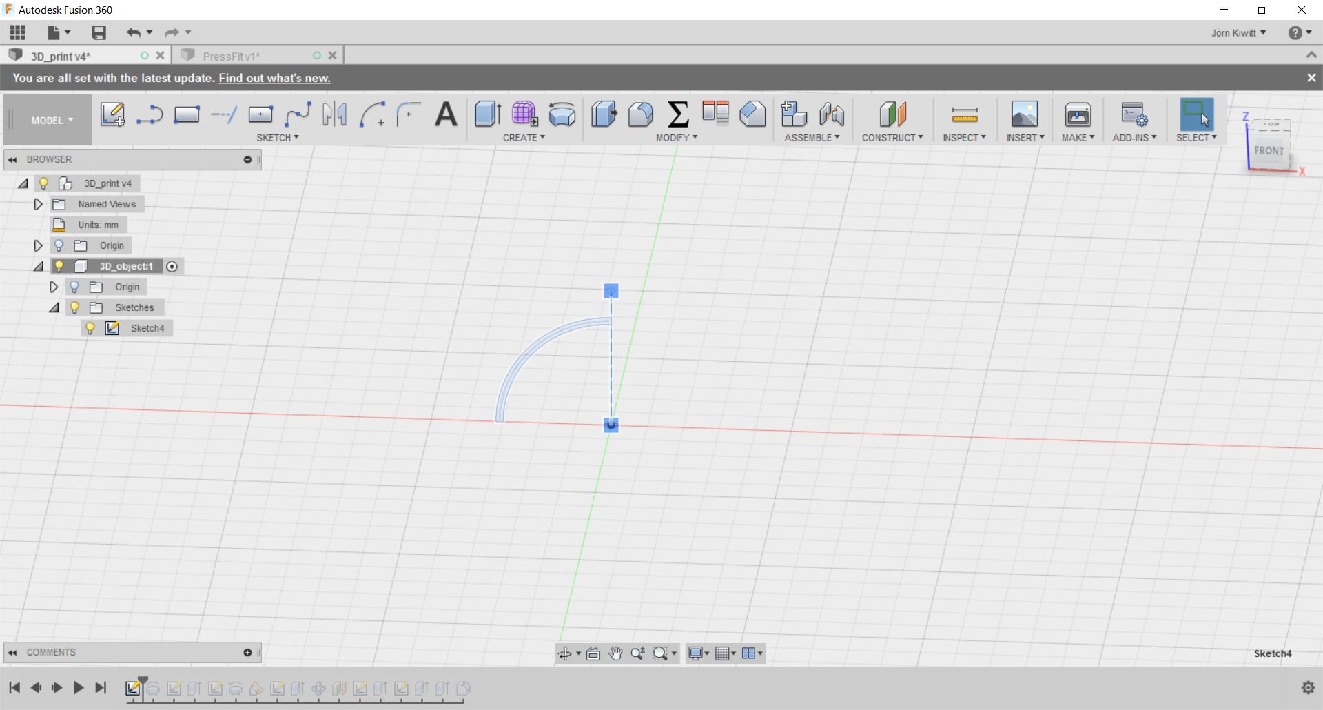
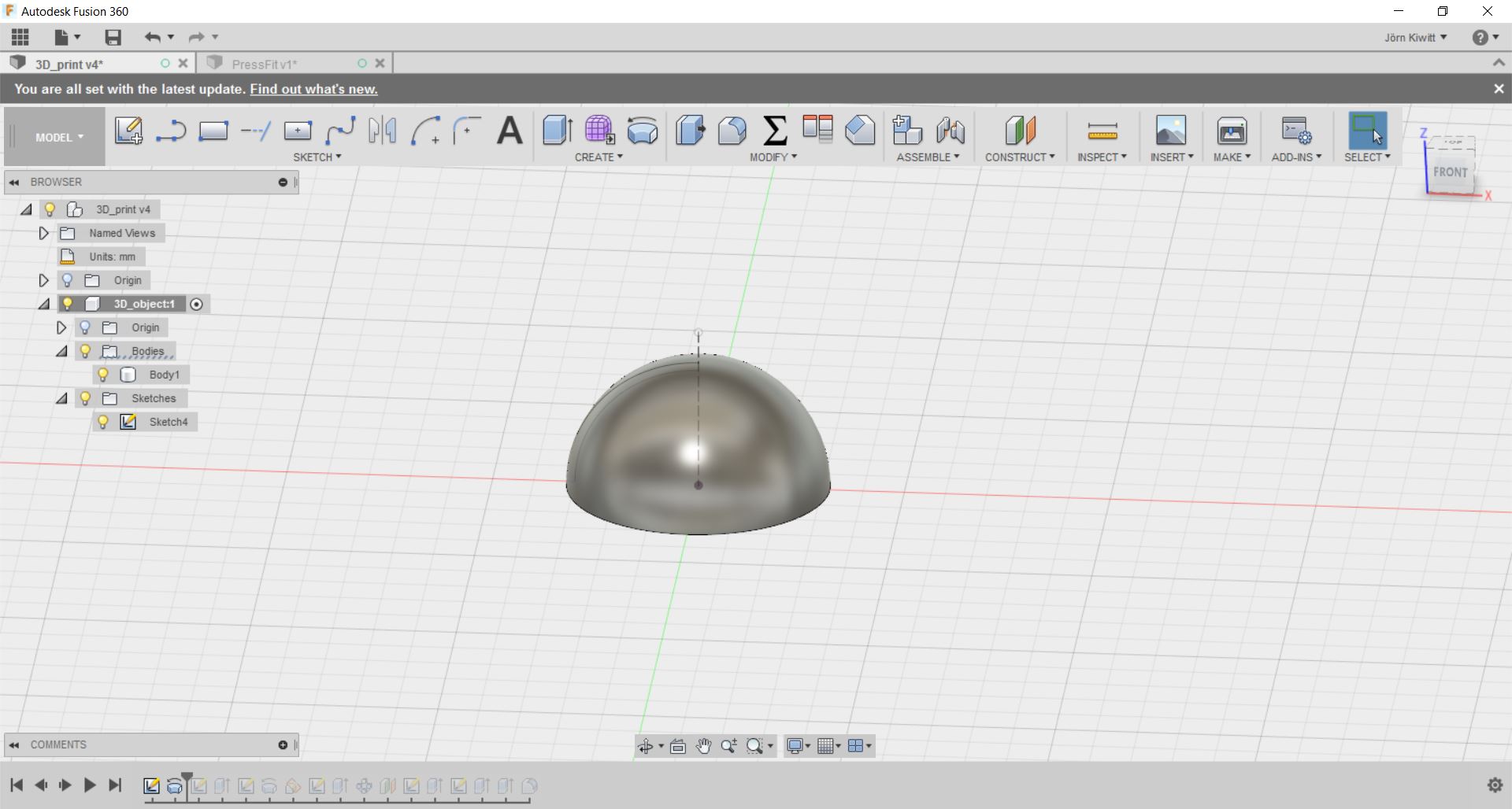
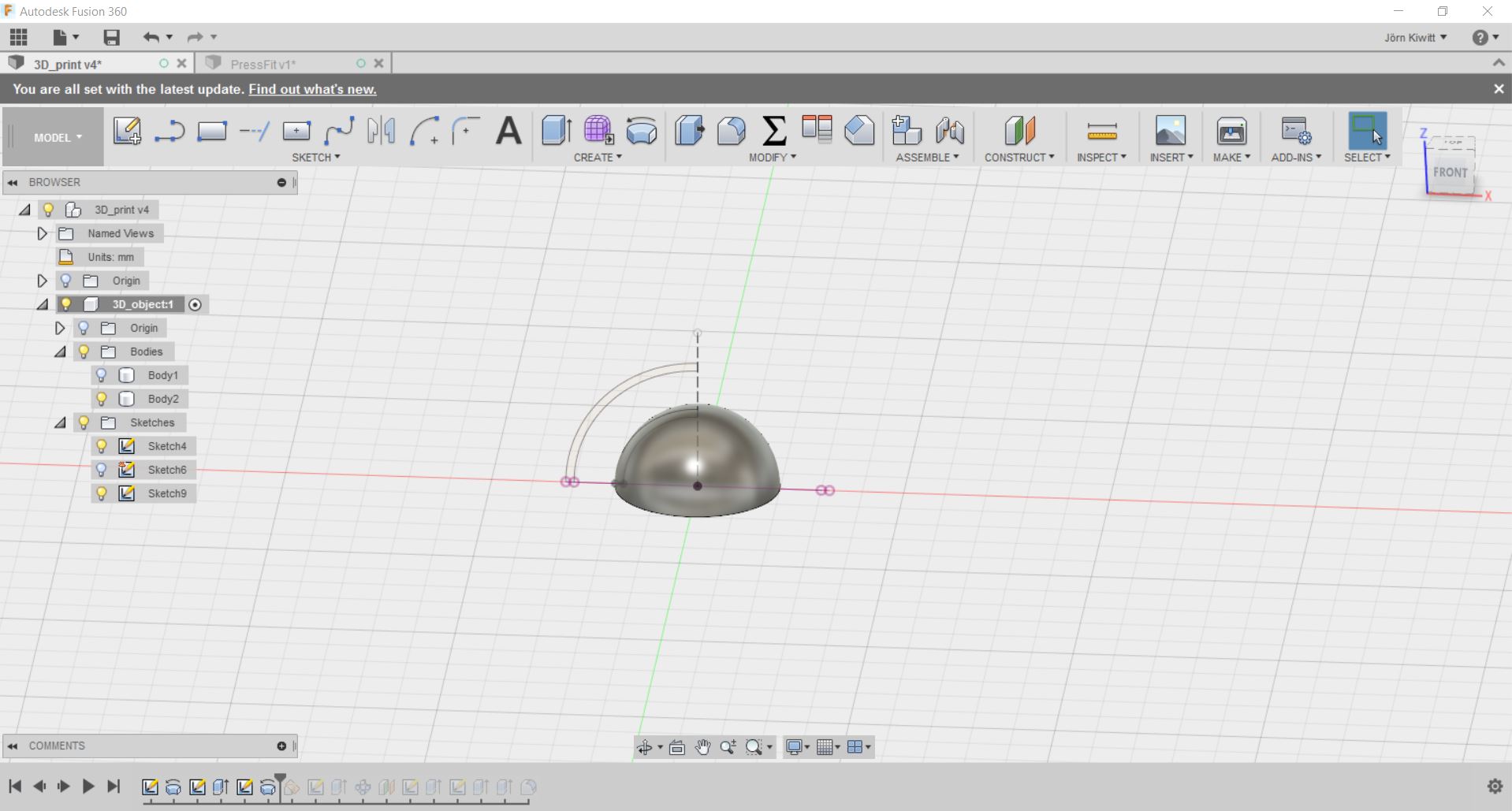

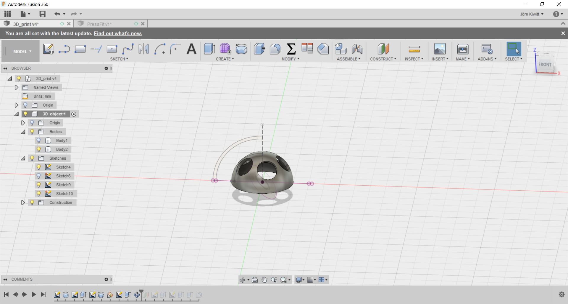
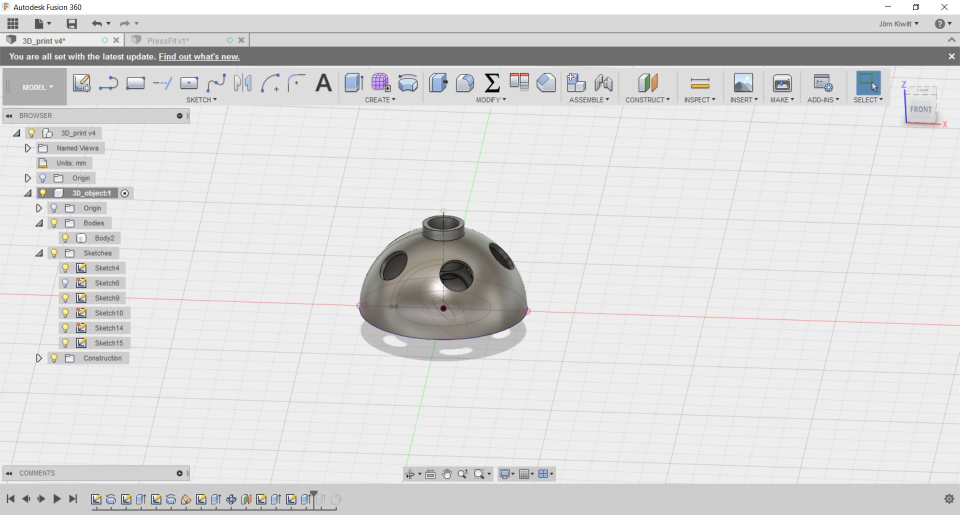
As this design contain an inner contour, which is closed, it cannot be made substractively.
Printing process
As the resolution is not as critical in this case, I used a rather coarse layer height of 0.3 mm. I printed the object again later with a layer height of 0.1 mm. The quality difference is indeed very well visible. To support the outer shell, I enabled support structures at an overhang angle of 50° and at a low support density of 5 % to enable easy removal (which did not work due to low offset).
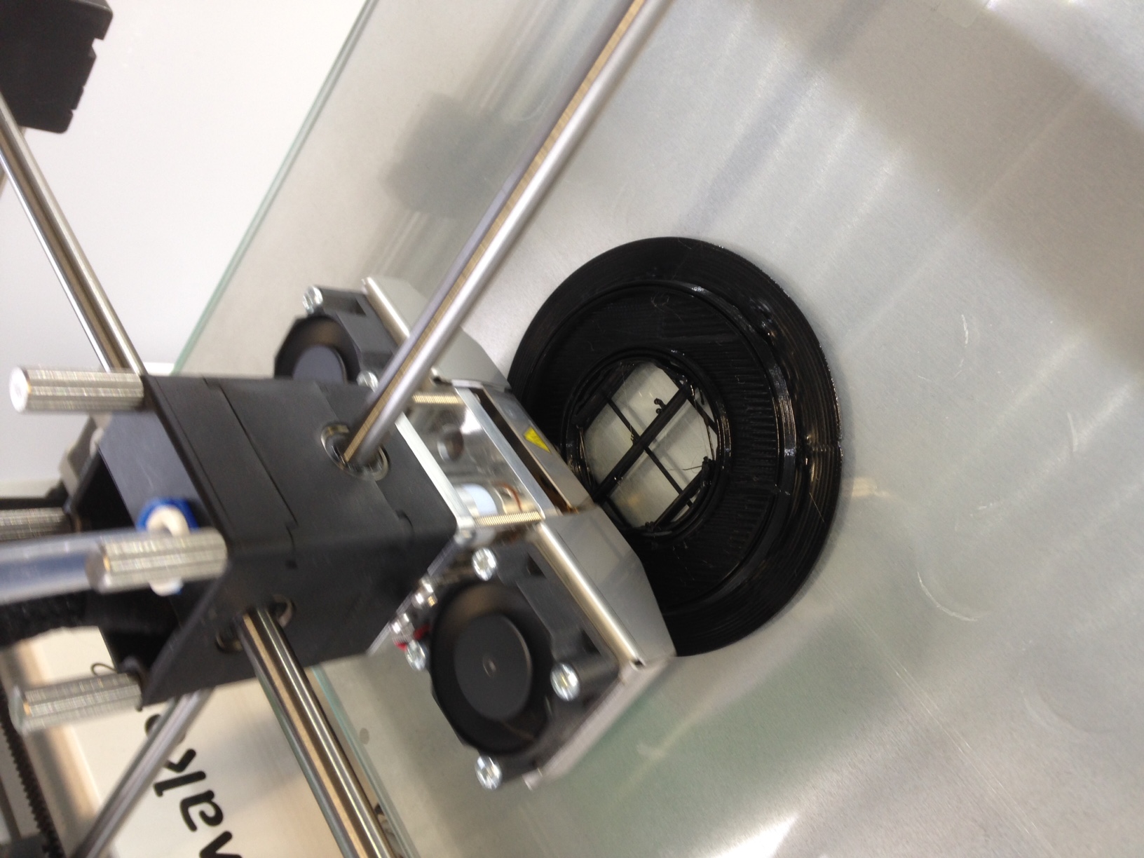
I saved the gcode to file on a SD card and put it into the Ultimaker's card slot. The file can then be selected and the print is executed (make sure to check whether enough material is available on the coil!). Now, the extruder and the bed will heat up. When the printing temperature is reached, the extruder will clean the nozzle by ejecting some filament before starting the actual print. The print itself takes about 1h 20 min. The first layer of the print should always be watched carefully. If the initial layer does not attach well to the build plate, the object will warp. This can be compensated by hairspray or blue tape on the build plate. In my case, the first layer came out just fine so no utilities were needed.
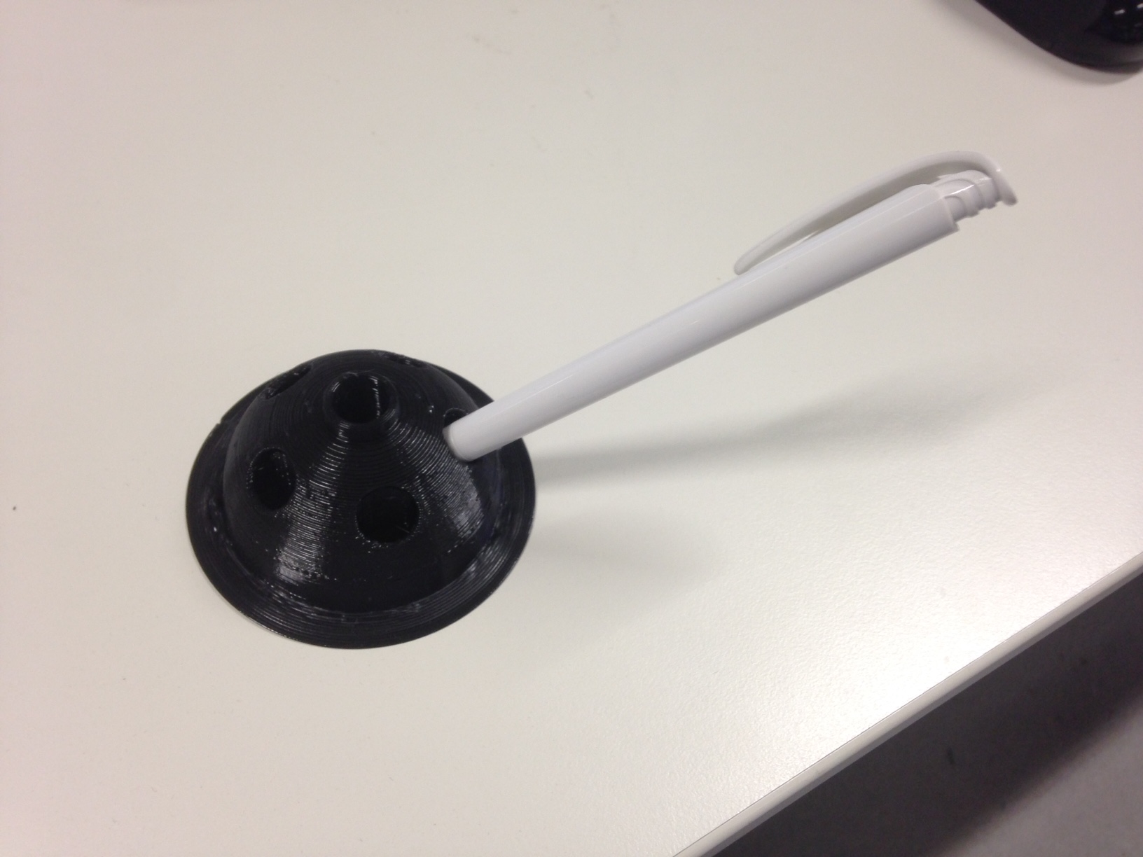
The finished part could be easily removed from the build plate. The brim as well as the support material were cut off, enabling the printed part to serve the need is was designed for - as a pen holder.
Group task: 3D printing
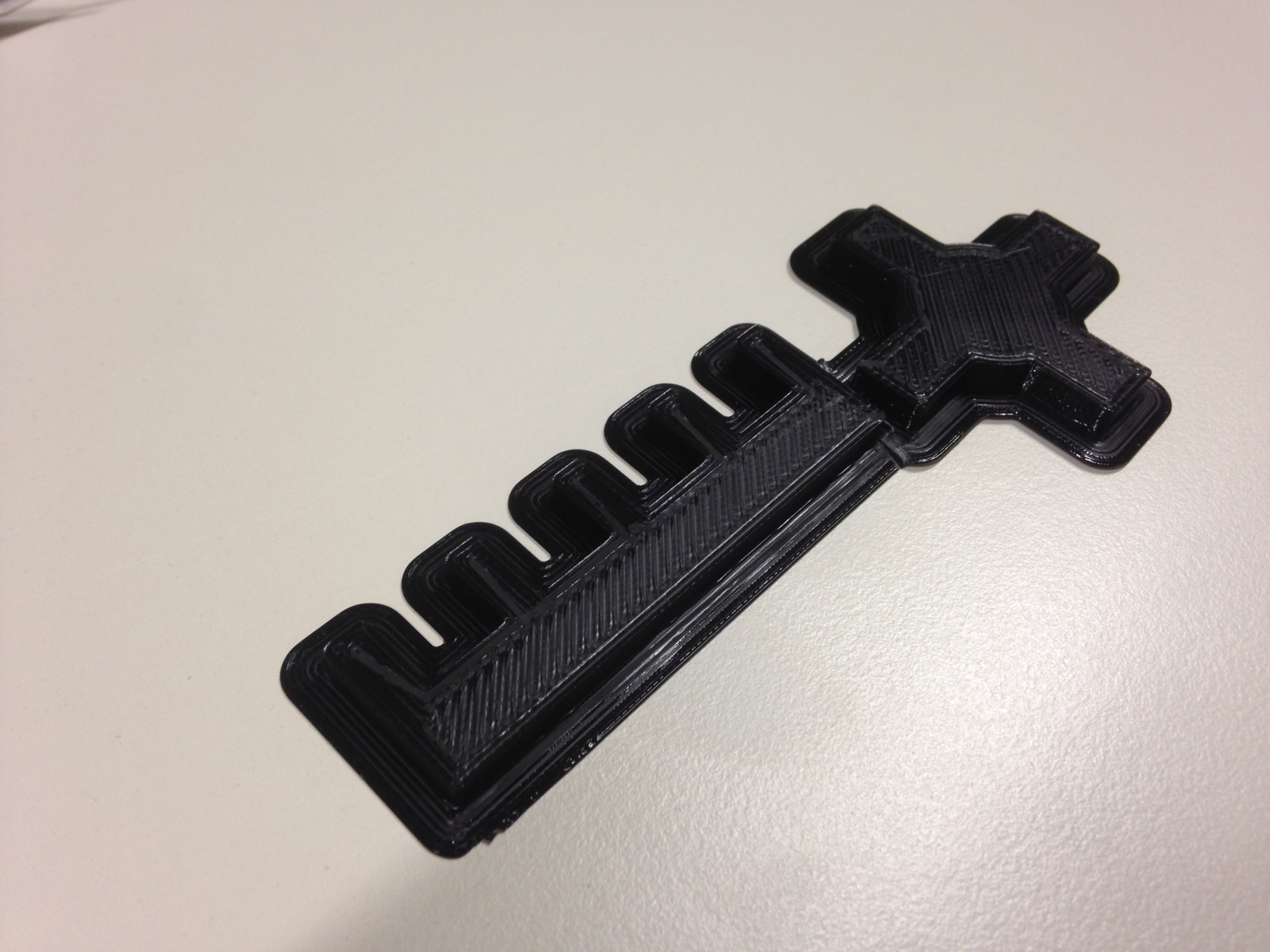
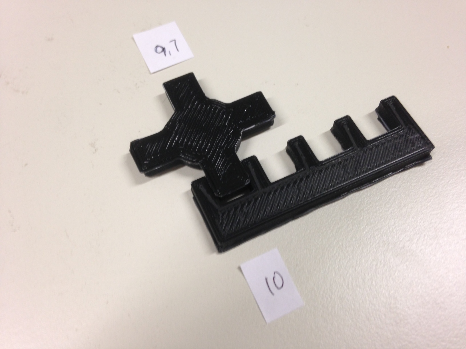
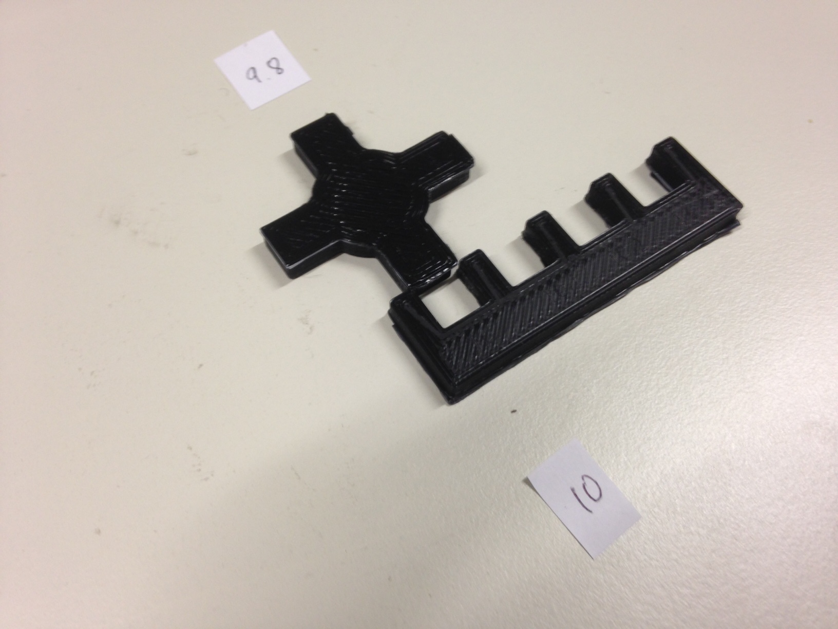
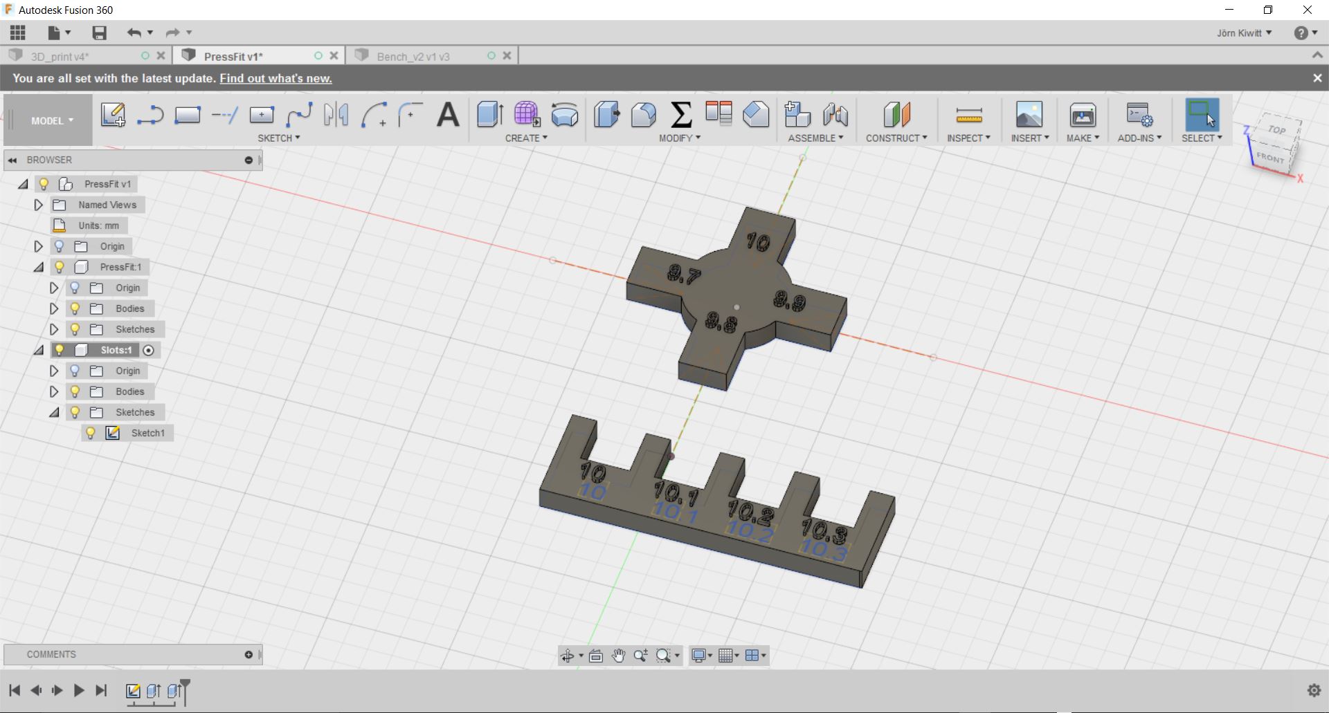
Within the group task, I wanted to test the accuracy of the printer by designing different of fittings. I did a similar test for the laser cutter to measure the kerf. In this case, I expect a slide offset in the positive direction.
Here is the design, I used to test my hypothesis. Again, I printed on the Ultimaker 2 Extended+ with a layer height of 0.2 mm in this case. Supposedly, the numbers on my design are too small in detail and were therefore neglected during the printing process.
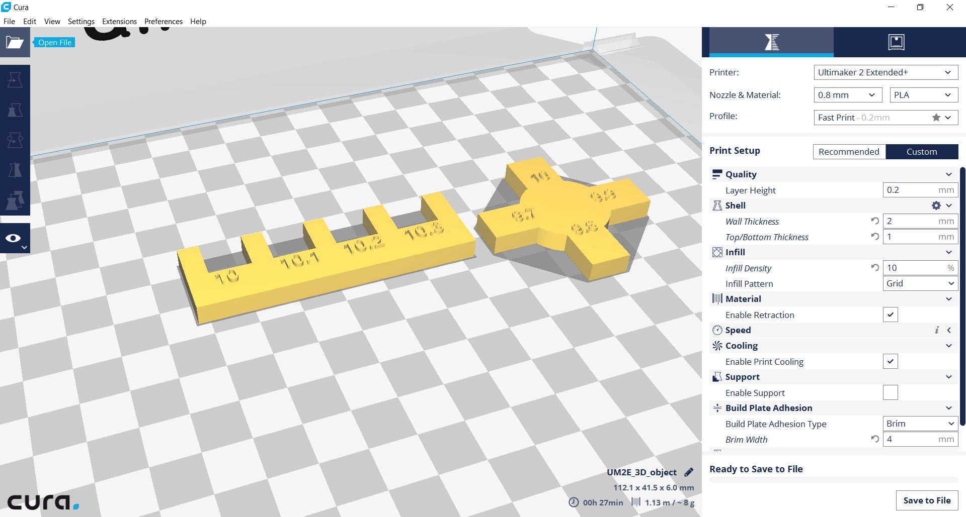
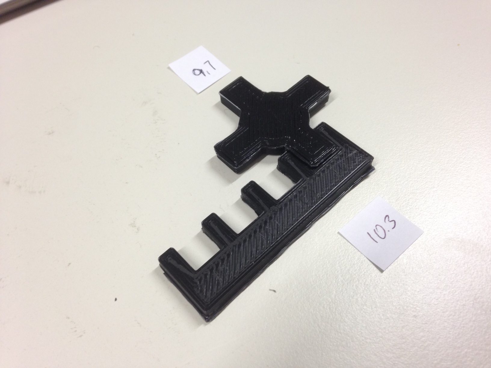
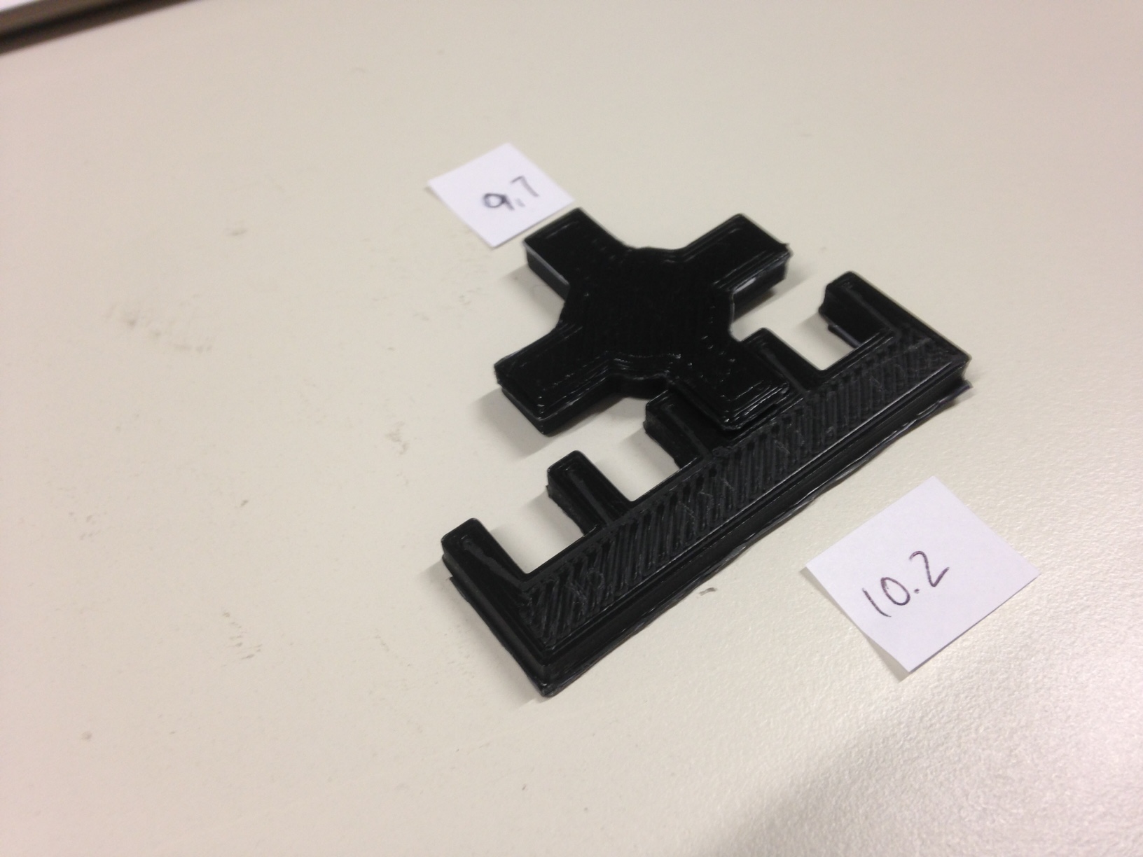
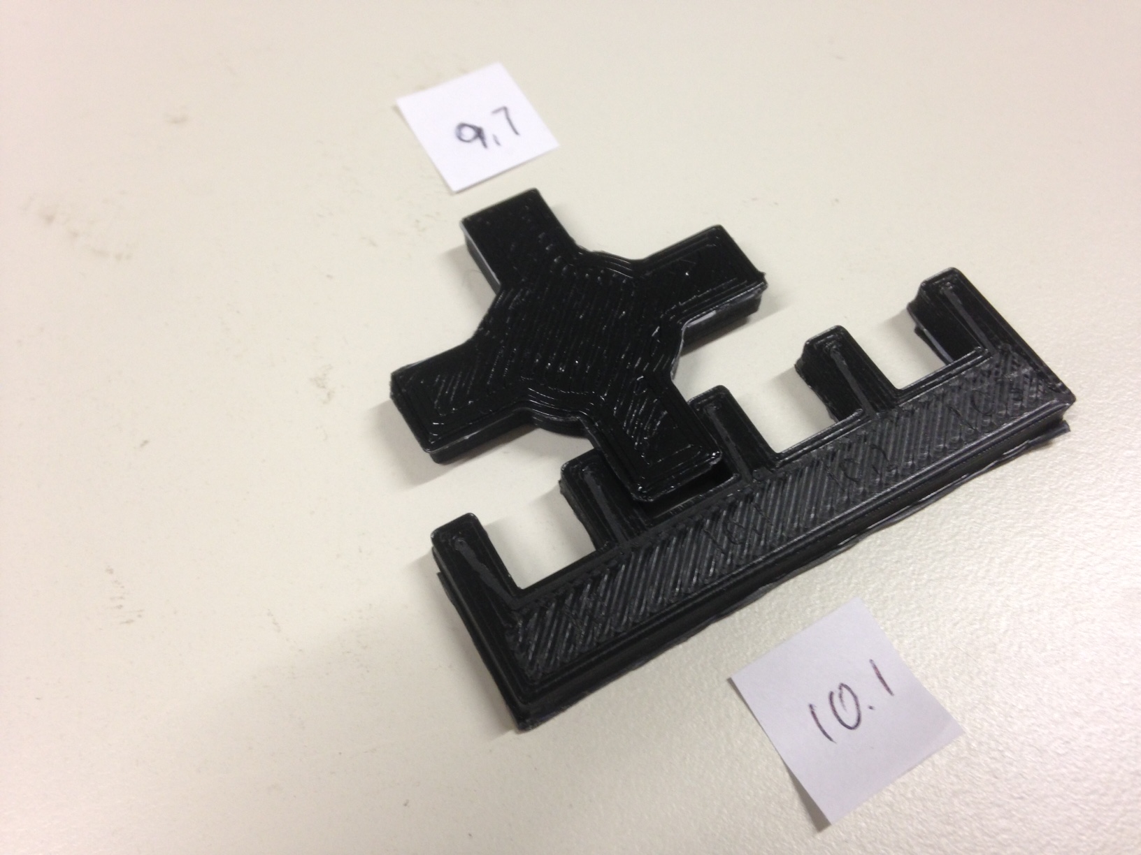
Measuring the result of the print with a caliper, the tongues turned out to be around +0.3 mm bigger and grooves around -0.3 mm smaller as designed. After removing the brim, I tested the fit. The smooth fit of the 9.7 mm tongue and the 10.3 mm groove acknowledged the accuracy measured. Deriving from this relationship will increase the tightness of the fit as found on the laser cutter.