Electronics Production
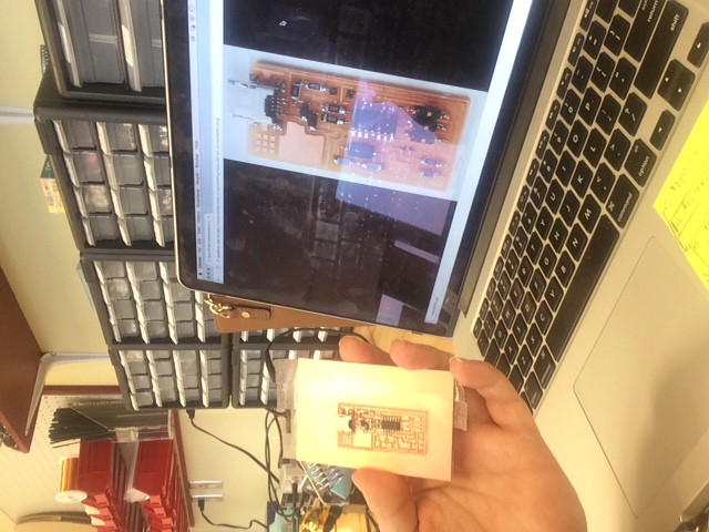
For week 3 projects, I will have to admit that I was a little nervous as this would be the first time that I have milled a circuit board. However, after getting started and walking through the process a few times I became more familiar with the equipment and was able to produce my very first circuit board. I choose to do the hello.ISP.44.cad board.
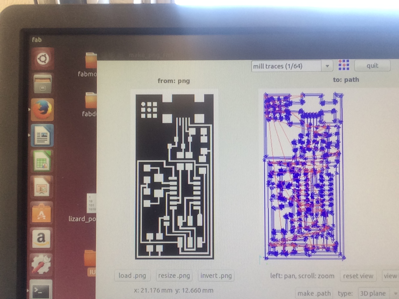
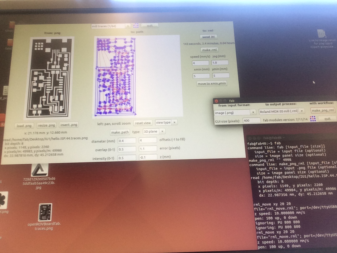
To begin this process I started Ubuntu, typed “fab” in the terminal system, once submitted by hitting enter the program needed to run the Roland MDX-20 opened. In order to complete the path for the hello ISP board, I first selected “from input format:” and chose image(.png), then from “to output process” selected my machine the Roland MDX – 20 (.rml), and then proceeded to “with workflow” to select make_png_rml. Once the completed the next window screen appeared where I then selected “load.png” and selected the “hello.ISP.44.traces.png” file.
This file was already set and ready to be printed as the image was in black and white. The white on the image is what would remain untouched on the circuit board and the black is what would be subtracted away. Once the image was loaded, I then selected “make.path” to create my tool path. In order to assure I achieved the appropriate depth and cut on the board I changed the mill traces to 1/64, which was the size of my bit (recommended for circuit boards), and the other information needed such as diameter, overall, and intensity was generated automatically.
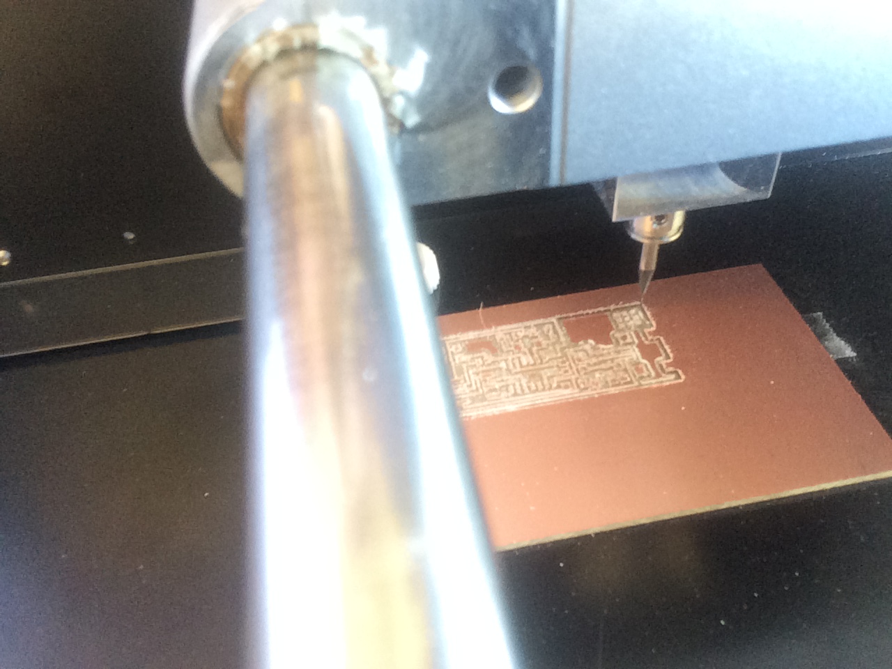
Before I sent the file to print I needed to make sure the material and the machine were set up appropriately. For the circuit board I placed double sided tape on the back and attached it to the mill surface (first try I did not use enough tape so make sure to use a generous amount). Since the mill doesn’t have an exact zeroing spot I lined my board up about 5 cm from the both the front and left edge, to bring the board to the front I selected “view” on the MDX-20 mill. The next step was to zero the material, for this I used the “go to y min, x min” on the computer and set it to “10,10” here the bit will move to this location on the plane, then on the MDX-20 I used the up and down arrow to lower the bit as close as it would go to the material. Next I lowered the bit manually to get it to lightly touch the top of the material. Once this was all set up I was ready to run the program.
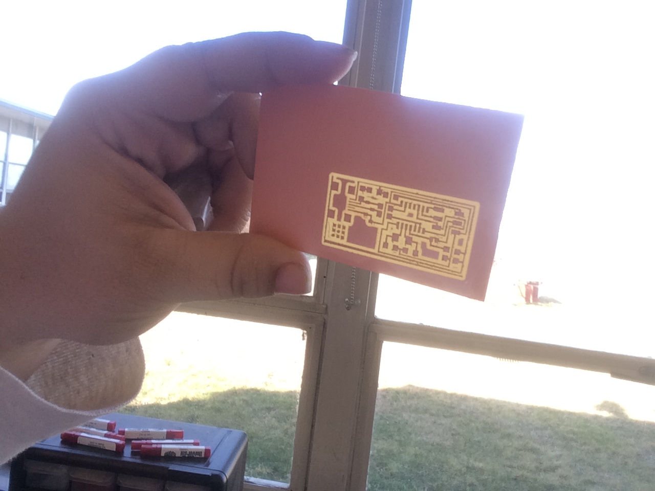
To run the path I next selected “make_rml” and then selected “send_it”. From here the last step was to select the final button to print the file. After that the fee was then sent to the MDX-20 and my circuit board began to be cut. As mentioned the first try didn’t go so well and I ended up doing three boards. On my first try the board moved, second the line was too thin next tot where the board was to be cut out. Third try went very well and I had my board I could then solder.
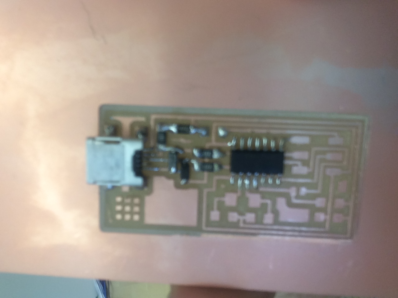
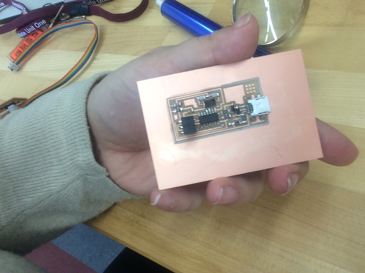
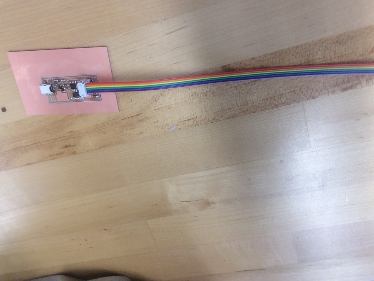
For soldering, I gathered all the needed components mentioned below and using the board layout as a guide began to place all the components in their corresponding locations. The hardest pieces were the two 10pF components, those took a couple try but eventually I was able to successfully solder them to the board. Once the board was soldered with all components I attached the appropriate wires to prepare for programming the board.
To program the ISP to be able to then program other boards, I followed a baisc tutorial and then recreated and recorded my steps in the following document:
File: ISP Programming Steps
Materials:
- Roland MDX-20 Desktop Mini Mill
- 1’64” Bit
- Copper PCB Circuit Board
- Soldering Iron
- Solder Coil
- Tweezers
- Double Sided Tape
Components:
- USB
- 2 – 3.3V
- 2 – 1000
- 1 – 1001
- 1 – 4990
- 1 – 1002
- 1 – T44
- 1 – MHZ
- 2 – 10PF
- 1 – 1UF
- 1 - ISP