Electronics Design
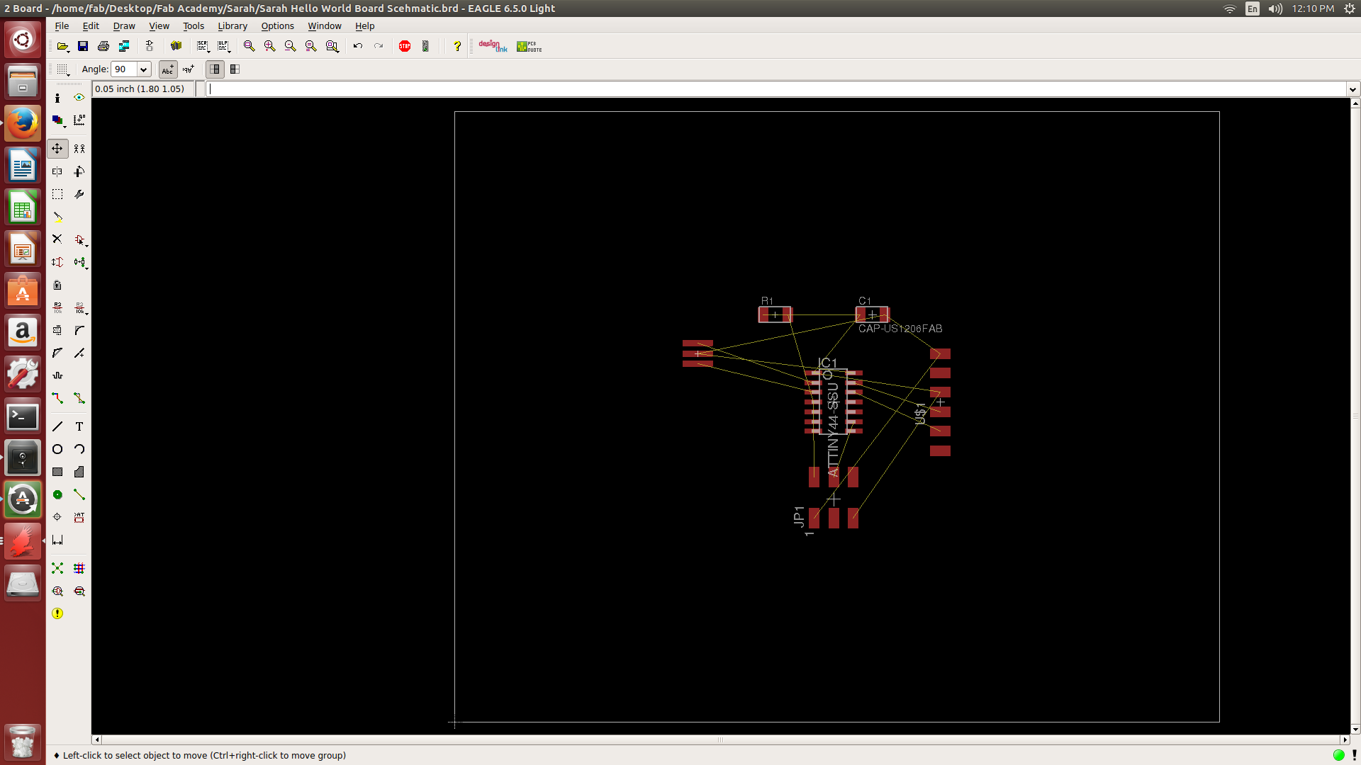
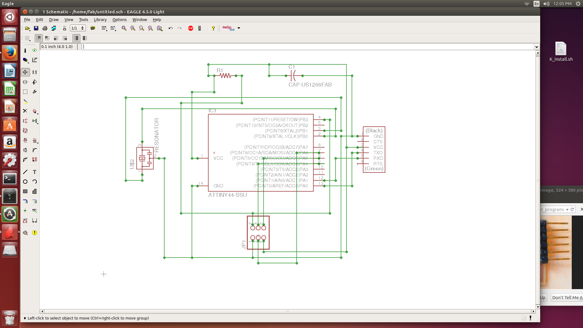
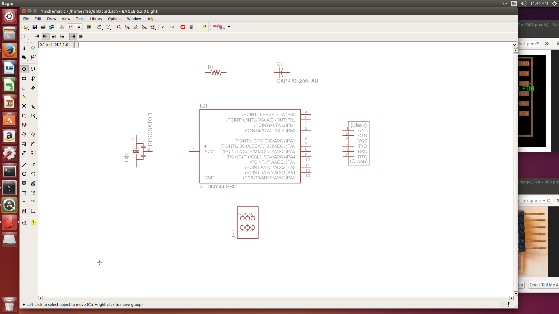
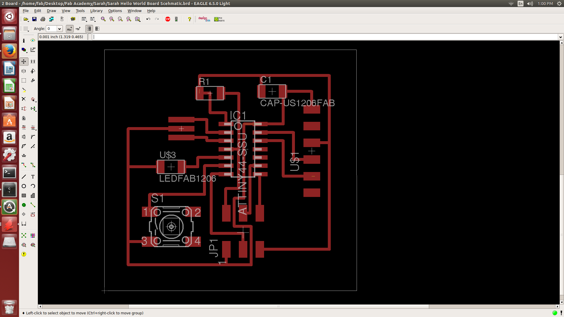
To create the Hello World Board the materials used were pcb board, Roland MDX-20 mill, doublesided tape, and software included Eagle. As a novice to programming and the Eagle software this project had me a little concerend however at the end it did prove to be a little simpler than first imagined. To redesign the board I loaded the schematic into the Eagle Program and then went through the process of adding the new components, which included a button and LED light. Following the previously supplied board image and schematic I began to connect the compontents using the wires. The first try I had a few components incorrectly connected or not at all but was able to make the correction to the schematic.
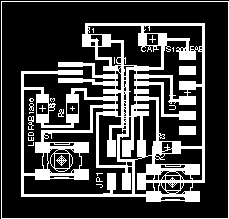
My main trouble proved to be not with the software but with the mill as I had to do several trouble shooting rounds before the board would print correctly. In the settings once 1/64 mill was selected the path was all rough as it was set at 1.1 however trying different settings I was able to correct the error and print a clean board. The new setting is 0.1 for the mill traces.
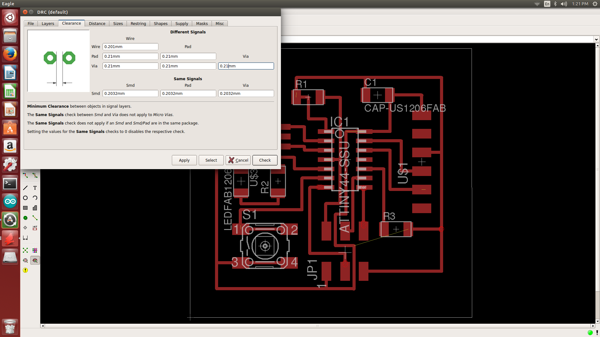
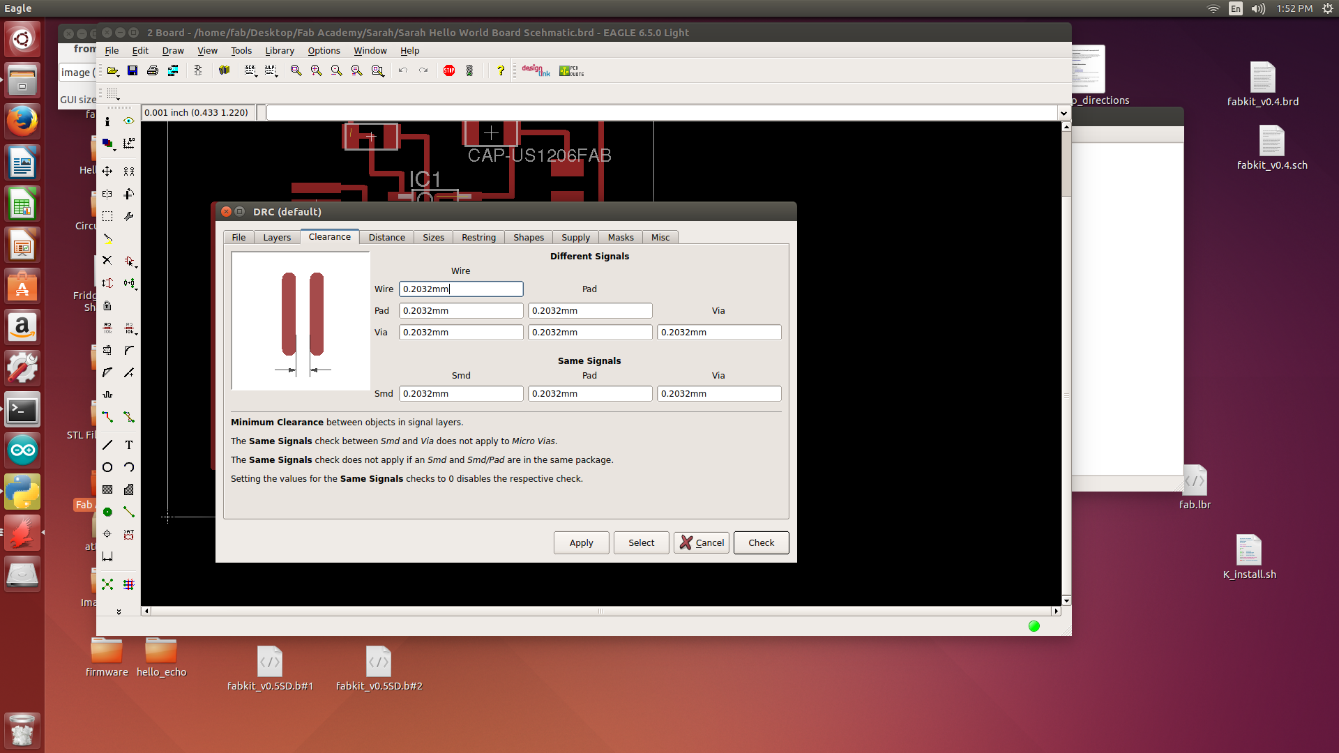
I went through the steps of moving the board, ripping up wires traces, and more to become comfortable using the Eagle program and after a few tries I was able to get the hang of building a circut board. The hardest part was getting the wires not to overlap or get too close that they wouldn’t print correctly. This was solved by using the DRC Checks and changing the settings appropriately. I also learned that you can change the width of the wire to make it thicker or thinner, which helped when several baords the traces were too thin and did not print at all.
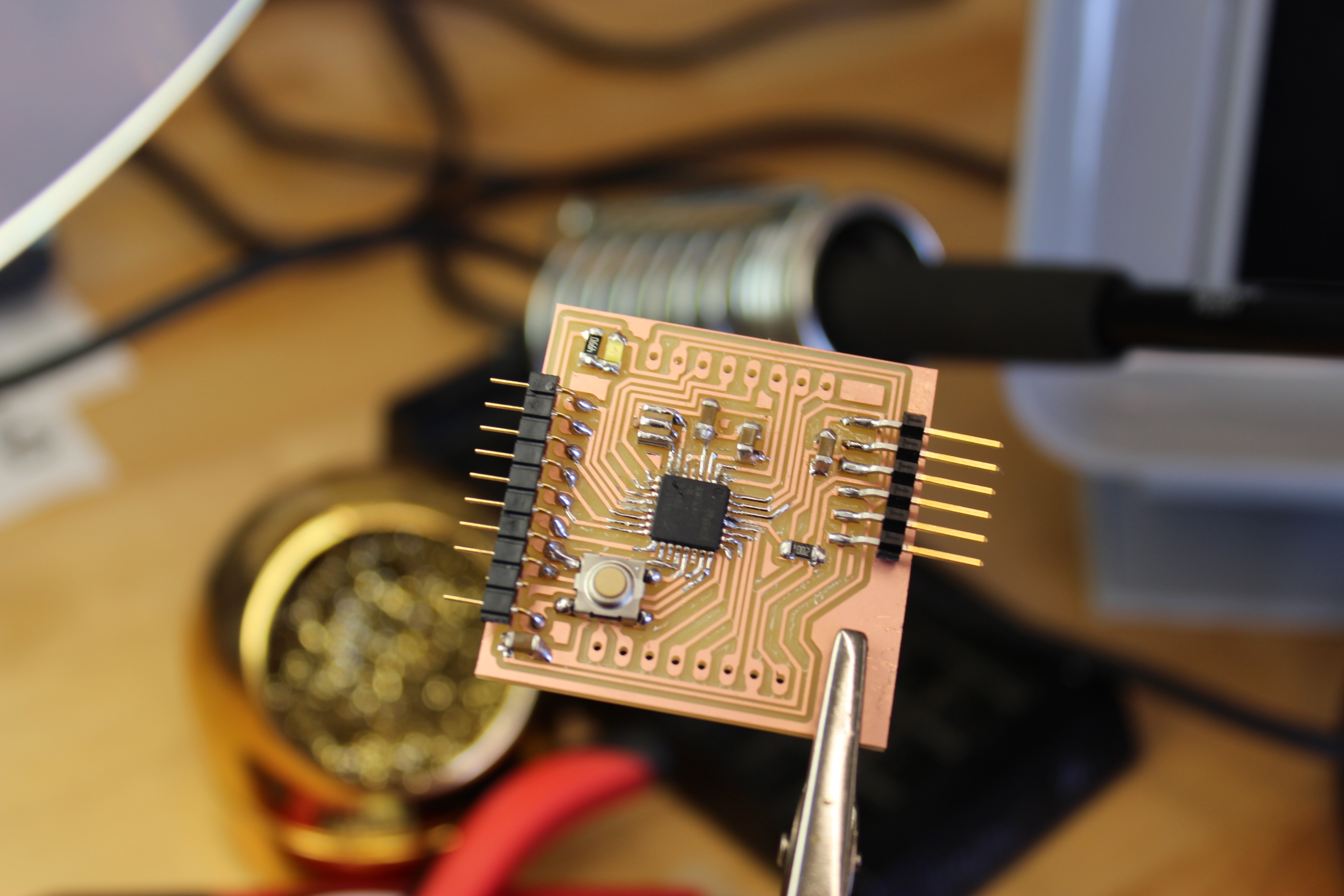
For the final part I found all the correct componets and the new componets and soldered the board. For my fisrt time adding new components it was not a bad run!
IMAGES & FILES