Input Devices
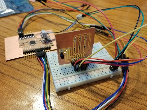
For Sarah and I’s input device, we used Eagle to design and trace a circuit that connects to our Satshakit (Arduino Uno Clone) to read a temperature sensor, which is a variable resistor that works as a voltage divider in order to send varying voltages to the Arduino serial monitor. These varying voltages are read as temperature levels which you can change the range of voltages on.
Components Needed:
Arduino Clone (Satshakit) Board
Breadboard
7 Male Pin Headers
X3 499Ω Resistors
X3 LEDs (Red, Orange, & Blue)
Temperature Sensor (LM35)
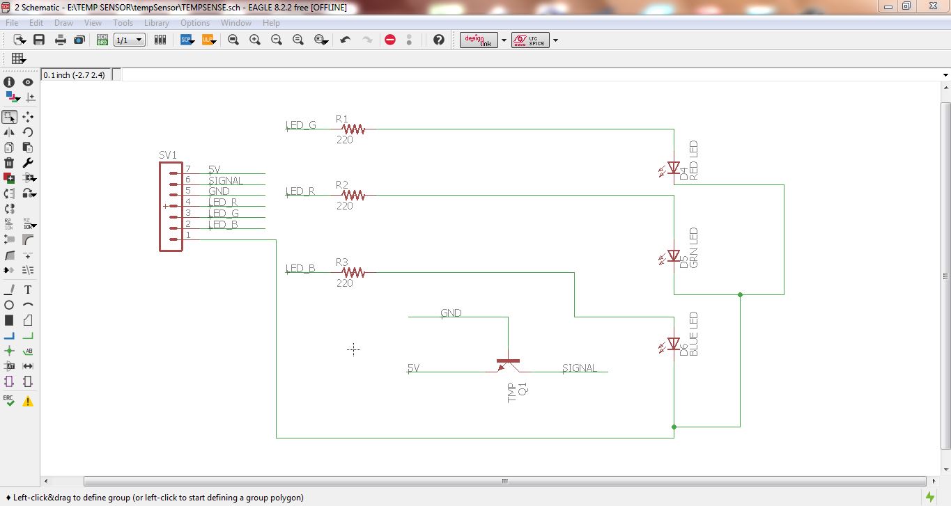
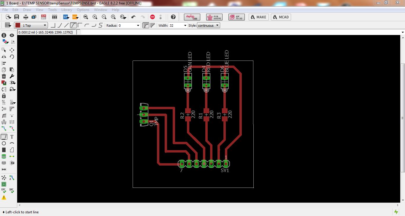
Designing the Traces:
HEADER PIN 1 - Pin one (the pin on the left) of the temperature sensor goes to 5v
HEADER PIN 2 - Pin two (the pin in the middle) of the temperature sensor goes to analog pin A2
HEADER PIN 3 - Pin three (the pin on the right) of the temperature sensor goes to ground
HEADER PIN 4 - Red LED through one of the resistors, and ground
HEADER PIN 5 - Orange LED though a resistor, and ground
HEADER PIN 6 - Blue LED through a resistor, and ground
HEADER PIN 7 - GROUND (For LEDs/Resistors)
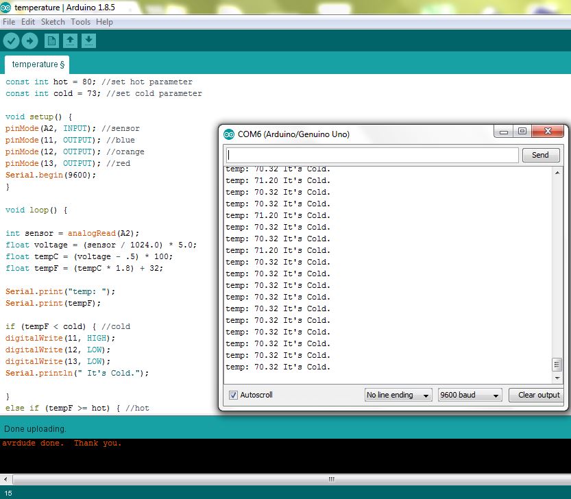
Coding
The basic understanding when making the code was first assigning all of the individual arduino pins to the LEDS/Temp Sensor, and then having a series HIGHS/LOWS listed to light up the specific LED per range of temperatures, along with a quick message stating cold, fine, and hot.
I was researching for good resources to start on a temperature-reading program. I found an excellent page to start me in the right direction when it came to making the SMD schematic along with the program itself, which I had to alter slightly. See source here: Arduino LED Temperature Indicator
The program is set so that a BLUE LED will turn on when temperature is below 75 degrees, an ORANGE LED turn on when it’s 73-80 degrees, and a RED LED turn on when it’s above 80 degrees. Below are the connections Sarah and I made, followed by the program we used to run the input device using Arduino IDE and it’s built in serial monitor:
Problems Encountered:
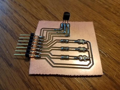
This was actually my second attempt on a Temp sensor circuit. The original one was using a SMD temperature sensor with 1 indicator light displaying with certain brightness. I decided to make it simplier with a more common (through-hole) Temp sensor that I can assign individual LEDs to for easier programming.