Embedded Programming
Creating the “Satshakit”
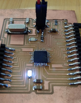
To start this assignment, I first took the advice of my Fab Academy mentor Jason W. in drawing and cutting out his 2015 Academy Final Project of the Satshakit, in the hopes to continue using Arduino IDE for all my programming needs from a fabricated PCB. The Satshakit is a clone of the Arduino Uno and is reconized on IDE as such. The link to Jason’s Satshakit project is located here: Satshakit
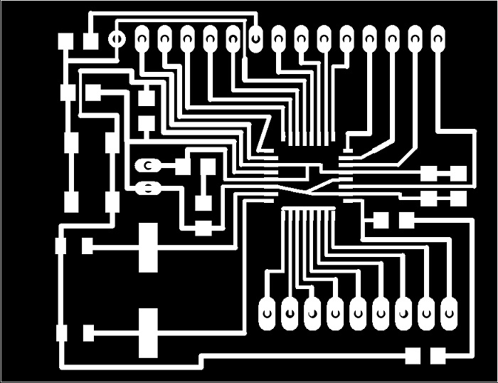
Because the orginal file had very fine traces for a laser etch operation, my Roland MDX-20 milling machine did not have the precision to smoothly cut the board.
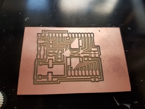
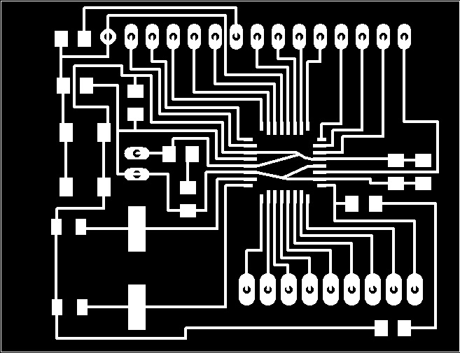
I then went into my Eagle software to re-trace every line on the board from a 0.012 to a 0.016 as shown below:
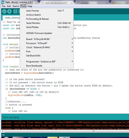
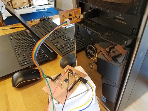
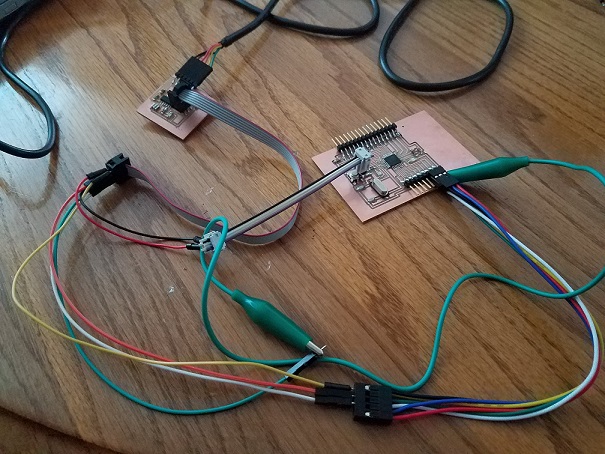
On Arduino IDE, I set the Board to “Arduino Uno”, Programmer to “USBtinyISP”, and then clicked Burn Bootloader. I then hooked up my Fab ISP to program the bootloader into the Satshakit with connections shown below.
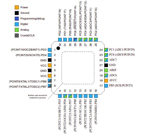
Understanding the Microcontroller (ATMEG 328P) Datasheet
Interesting facts learn about the chip, which I am using for the Satshakit:
- It has 32 pins total, 23 of which are I/O’s
- It’s power supply should be between 1.8-5.5V for running at 20MHz
- Pin layout of where and what different connections are made onto the chip, shown here:
Programming the “Hello World” Board
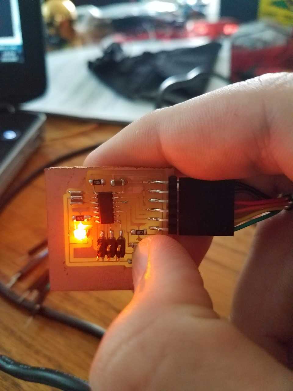
Below shows the following connections I made from the Sathakit to my “Hello World” board made in a previous assignment: Electronics Design. The reason for the excessive wires was due to a shortage of female connector ends, and being imaginative on joining all of the pins for the following: POWER (5V), GROUND, RESET, MISO, MOSI, and SCK, followed by plugging in the FDTI 5V Cable into the Echo Board.
Here are the settings I sent over from Arduino IDE and how the program was connected: