Final Project
DIY Digital Clock Lesson
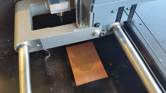
The idea is to adapt what I’ve been learning in Fab Academy to create a project that can be used as an advance high school lesson. This project is to design and program a copper-traced board that is cut from our milling machines. Once the circuit is done, a casing will then be designed and created from one of many fabrication processes we offer in our Fab Lab program.
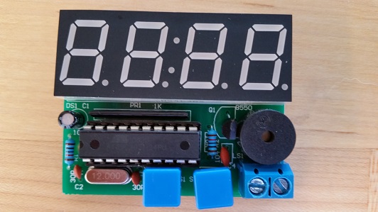
I started this project by designing a enclosure for the circuit. I looked around for a through-hole kit that was already designed to base my schematic off of for surface mounting.
Designing a Casing Through Vectors (Adobe Illustrator)
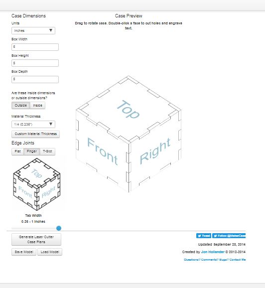
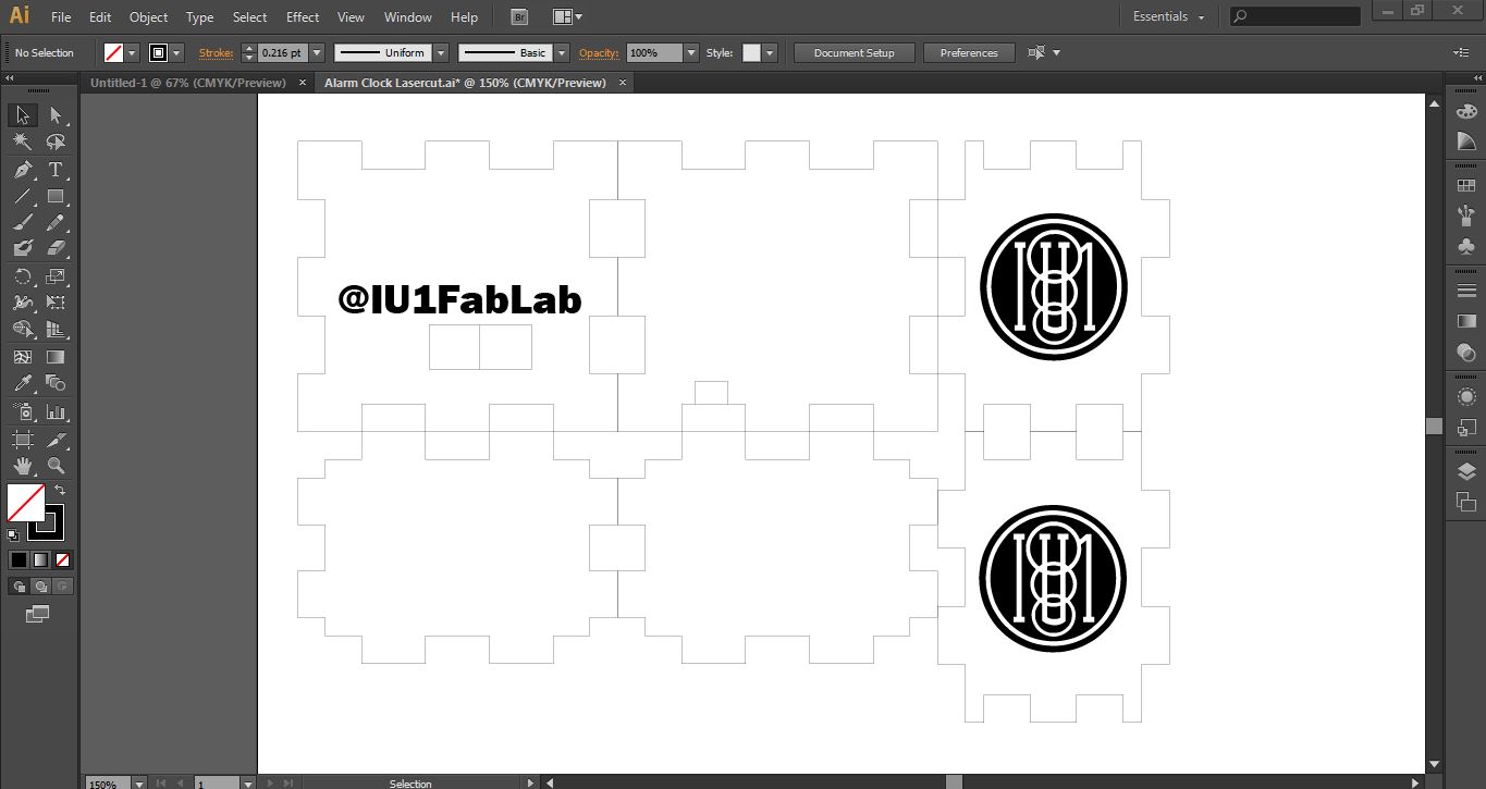
I started by utilizing www.makercase.com which is a simple sketch generator to design a basic box shape with a percise finger joint layout. I chose this program because of it all being parametric, and good for projects with joinery. Once I plugged in the few parameter questions, it generated a .SVG file which can then be pulled into other vectoring software. I decided to experiment with Adobe Illustrator by importing, designing, and manipulating the file that will somday be either lasercut or CNC milled.
Using Adobe Illustrator:
To make this kind of design, I knew I would need a software that is great with node editing features that is also better than Inkscape. I’ve personally only used CorelDRAW in my lab during my time here as manager so I wanted to see the difference in this software. Obviously, the 2 liscenses are more alike than different. The only major differences is the tool layouts and labels for those tool features.
Features Used:
Type Tool (With Features)
Various Line Segment Tools
Direct Select Tool (Node Editing)
Image Trace (Pixels into Vectors)
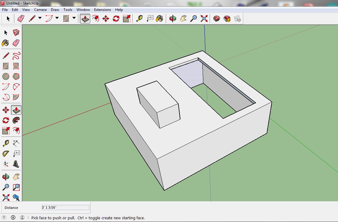
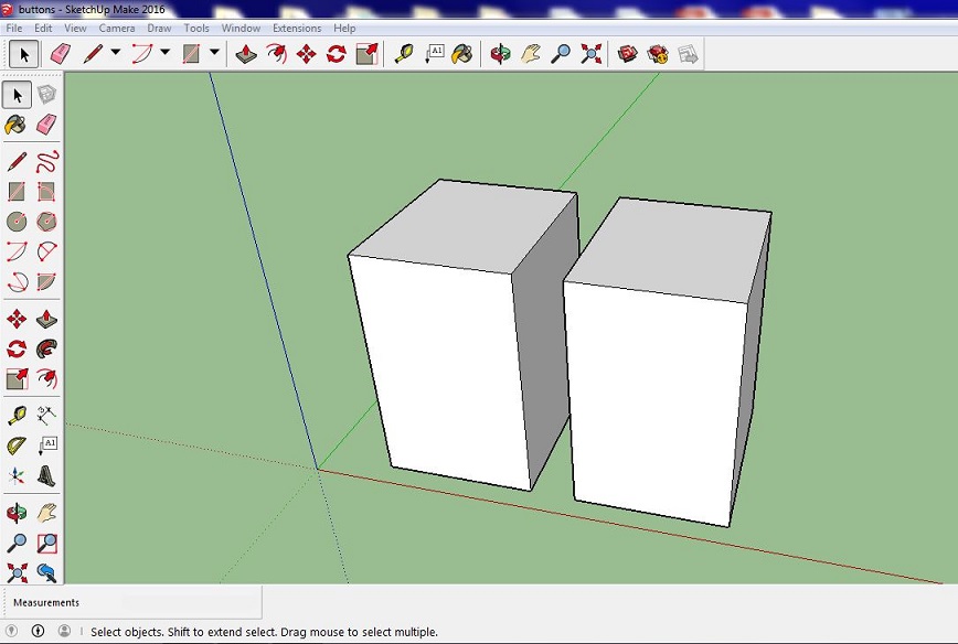
Designing a Casing Through 3D Modeling (Google SketchUp)
As a option for our students, I am considering 3D printing as a viable option to create their casing. Below is a version I made that took just around 1-2 hours to print, which is considerable time for me to instruct a small class from my mobile lab.
Using Google SketchUp:
To incorporate the 3D modeling aspect for my project, I thought of using SketchUp as my primary learning tool. I’ve taught in Elem/Middle school areas when it comes to this kind of 3D printing where it can be simple, fun, and very accessable to the students. Other software that I have used for this kind of application include Tinkercad & 123D Design. I always found those two programs very similar on how they manipulate shapes and wanted to go a slightly different way. SketchUp is free like the others so I found this appealing to adapt in these same sort of classes I teach, where even younger students can load this program on their own personal computer.
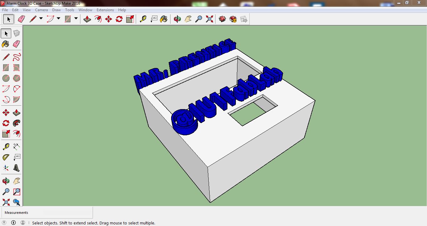
I started with a simple cube shape where I subtracted away all of the hollow areas that you see in the pictures below. Once I made my guesses on where to put the openings for the buttons & 7-segment display, I “pushed” the 2D shapes inward to subtrate the material away. My last step was to add the 3D text on top, extruding it in such a way that I can switch colors of filiment during prints to bring out more contrast.
Features Used:
Rectangle
3D Text
Push/Pull
Navagation Tools (Move, Rotate, Offset, Orbit, etc.)
Tape Measure Tool
Paint Bucket
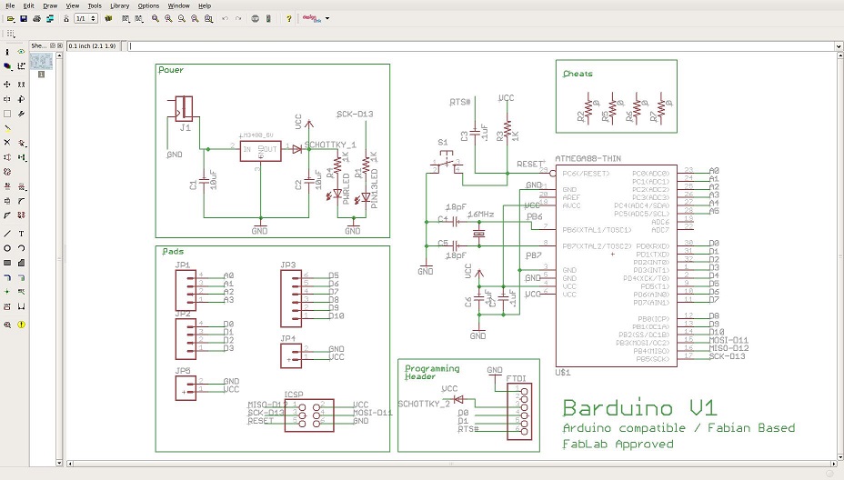
Making the 1st Schematic Attempt
I starting this process by studying the schematic/parts list for the orginal circuit I bought from China. Once I understood all of the parts, I went to our class archives to pull the Barduino board design to start from.
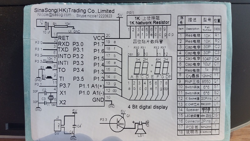
Official Barduino Schematic:
From reviewing our Fab Lab inventory again with our SMDs in particular, I drafted a Google sheet organizing parts that our lab has already along with parts I need attached to specific vendors I found selling them cheap.
Both Original and Surface Mounted Materials Chart
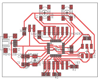
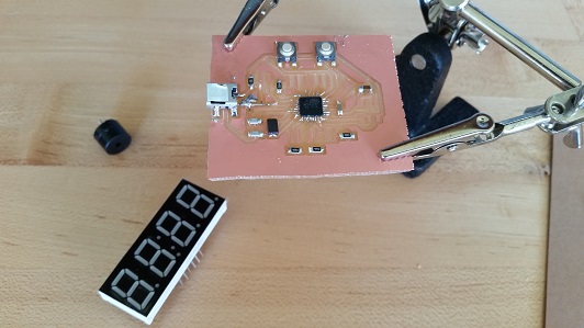
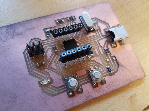
Using Eagle, I drafted the first schematic from the barduino by adding the buzzer, USB power supply, 7 segment display, and the buttons. Once completed, I traced everything appropriately, having the 7 segment display hovering over the entire board from extra legnth prongs that will still be soldered onto with surface mounts.
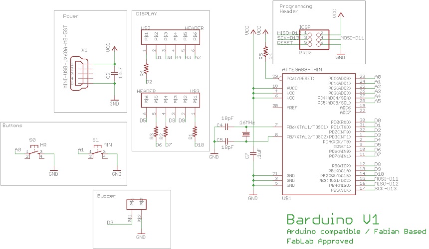
Reflecting on 1st Schematic Attempt
Improvements to consider:
- Eliminating the x4 (499ohm) resistors going into the display (doing this does not burn out LEDs)
- Slightly moving over the 6 pin programming header so display doesn’t have to be unplugged to upload program.
- Create a larger footprint for the (16mHz) crystal for easier soldering.
Connecting to the “Satshakit” (Arduino Uno Clone)
Using my Arduino Clone that I’ve re-traced in earlier assignments, I was now able to program with Arduino IDE to set up the code shown further below. The reason for all of the excess wires/breadboard usage was due to having no female plugs for the header pins.
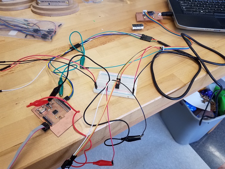
After the connections were made, I preceded by first uploading the “TimerOne” library onto the IDE and then sending the file over with the command “Upload Using Programmer” under the Sketch tab.
Setting Up the Program:
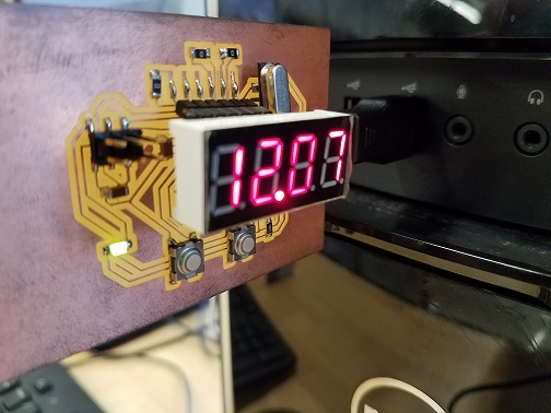
The first task involved with writing the program was getting the display to work. I used the 7 segment display datasheetto determine the function of each pin. I wrote code to set the segment pins correctly to display a digit. The display is multiplexed so only one digit can actually be displayed at a time but uses the ATMega’s speed to display each digit sequentially many times a second. This speed tricks the eye into thinking that all of the digits are displayed simultaneously.
The next task was using the ATMega’s timer to accurately count in one second intervals. I used the TimerOne library to abstract away the technical details so I only had to write the time handling code that occurs every second. Since this clock uses 12 hour time, I also added an AM and PM LED which are set depending on the time of day.
I added button control code which treats the buttons as interrupts and debounces their switching. This results in quick button detection and smooth switching. I used the tone() function to send a little beep to the buzzer so the user knows when the button is pressed. This buzzer is also used to sound an hourly chime and play the alarm when it goes off.
The last task was adding the software control to mimic the original clock’s functionality. The left button cycles through setting the hour and minute, turning the hourly chime on or off, setting the hour and minute of the alarm, and turning that alarm on or off. When the clock is in normal operation, pressing the right button switches between HH:MM display and MM:SS for keeping accurate track of time.
1
2
3
4
5
6
7
8
9
10
11
12
13
14
15
16
17
18
19
20
21
22
23
24
25
26
27
28
29
30
31
32
33
34
35
36
37
38
39
40
41
42
43
44
45
46
47
48
49
50
51
52
53
54
55
56
57
58
59
60
61
62
63
64
65
66
67
68
69
70
71
72
73
74
75
76
77
78
79
80
81
82
83
84
85
86
87
88
89
90
91
92
93
94
95
96
97
98
99
100
101
102
103
104
105
106
107
108
109
110
111
112
113
114
115
116
117
118
119
120
121
122
123
124
125
126
127
128
129
130
131
132
133
134
135
136
137
138
139
140
141
142
143
144
145
146
147
148
149
150
151
152
153
154
155
156
157
158
159
160
161
162
163
164
165
166
167
168
169
170
171
172
173
174
175
176
177
178
179
180
181
182
183
184
185
186
187
188
189
190
191
192
193
194
195
196
197
198
199
200
201
202
203
204
205
206
207
208
209
210
211
212
213
214
215
216
217
218
219
220
221
222
223
224
225
226
227
228
229
230
231
232
233
234
235
236
237
238
239
240
241
242
243
244
245
246
247
248
249
250
251
252
253
254
255
256
257
258
259
260
261
262
263
264
265
266
267
268
269
270
271
272
273
274
275
276
277
278
279
280
281
282
283
284
285
286
287
288
289
290
291
292
293
294
295
296
297
298
299
300
301
302
303
304
305
306
307
308
309
310
311
312
313
314
315
316
317
318
319
320
321
322
323
324
325
326
327
328
329
330
331
332
333
334
335
336
337
338
339
340
341
342
343
344
345
346
347
348
349
350
351
352
353
354
355
356
357
358
359
360
361
362
363
364
365
366
367
368
369
370
371
372
373
374
375
376
377
378
379
380
381
382
383
384
385
386
387
388
389
390
391
392
393
394
395
396
397
398
399
400
401
402
403
404
405
406
407
408
409
410
411
412
413
414
415
416
417
418
419
420
421
422
423
424
425
426
427
428
429
430
431
432
433
434
435
436
437
438
439
440
441
442
443
444
445
446
447
448
449
450
451
452
453
454
455
456
457
458
459
460
461
462
463
464
465
466
467
468
469
470
471
472
473
474
475
476
477
478
479
480
481
482
483
484
485
486
487
488
489
490
491
492
493
494
495
496
497
498
499
500
501
502
503
504
505
506
507
508
509
510
511
512
513
514
515
516
517
518
519
520
521
522
523
524
525
526
527
528
529
530
531
532
533
534
535
536
537
538
539
540
541
542
543
544
545
546
547
548
549
550
551
552
553
554
555
556
557
558
559
560
561
562
563
564
565
566
567
568
569
570
571
572
573
574
575
576
577
578
579
#include <TimerOne.h>
// letter n for displaying "on"
#define N 16
// special parameters to handle decimal point
#define DP_ON 17
// this is a general parameter to turn any segment off
#define BLANK 18
// pinouts for common cathode 7 segment LED display:
// segment is active high
// segment | display | header | mcu
// A 11 D9 PB1
// B 7 D5 PD5
// C 4 D0 PD0
// D 2 A3 PC3
// E 1 A2 PC2
// F 10 D8 PB0
// G 5 D1 PD1
// DP 3 A4 PC4
// digit is active low
// digit | display | header | mcu
// 1 12 D10 PB2
// 2 9 D7 PD7
// 3 8 D6 PD6
// 4 6 D2 PD2
// settings state
// these values make the code easier
#define DISPLAY 9
#define SET_HR 0xA
#define SET_MIN 0xB
#define SET_CHIME 0xC
#define SET_ALARM 0xD
#define SET_ALARM_HR 0xE
#define SET_ALARM_MIN 0xF
void ledSetup(void);
void ledAm(void);
void ledPm(void);
void buttonsSetup(void);
void buttonsS1(void);
void buttonsS2(void);
void nextSettingState(void);
void increaseSecond(void);
void increaseHour(void);
void displaySetup(void);
void displayDigits(int dig1, int dig2, int dp, int dig3, int dig4);
void setDigit(int digit, int number);
void setSegment(int number);
// displaying time
int sec = 0;
int min_1 = 0;
int min_10 = 0;
int hr = 12;
// decimal point
int dp = 0;
// switch between HH:MM and MM:SS
int hr_display = 1;
// differentiate between AM and PM
// 0 = AM // 1 = PM
int time_of_day = 1;
// default to display mode
int settings_mode = DISPLAY;
// hourly chime on or off
int hr_chime_enabled = 1;
// alarm on or off
int alarm_enabled = 1;
// alarm time
int alarm_hr = 12;
int alarm_min = 0;
// capture only 1 button press (kinda like debouncing)
int buttonBlockA0 = 0;
int buttonBlockA1 = 0;
void setup() {
// set display pins to outputs
displaySetup();
// set LED pin to output
ledSetup();
// set button pins to interrupt-enabled inputs
buttonsSetup();
// setup timer for 1 second tick
Timer1.initialize(1000000);
Timer1.attachInterrupt(increaseSecond);
}
void loop() {
// displayDigits in loop so they keep updating
// default display mode
if (settings_mode == DISPLAY)
{
// HH:MM
if(hr_display)
{
displayDigits(hr/10, hr%10, dp, min_10, min_1);
}
// MM:SS
else
{
displayDigits(min_10, min_1, dp, sec/10, sec%10);
}
}
else if (settings_mode == SET_HR)
{
displayDigits(SET_HR, BLANK, BLANK, hr/10, hr%10);
}
else if (settings_mode == SET_MIN)
{
displayDigits(SET_MIN, BLANK, BLANK, min_10, min_1);
}
else if (settings_mode == SET_CHIME)
{
// on
if (hr_chime_enabled)
{
displayDigits(SET_CHIME, BLANK, BLANK, 0, N);
}
// off
else
{
displayDigits(SET_CHIME, 0, BLANK, 0xF, 0xF);
}
}
else if (settings_mode == SET_ALARM)
{
// on
if (alarm_enabled)
{
displayDigits(SET_ALARM, BLANK, BLANK, 0, N);
}
// off
else
{
displayDigits(SET_ALARM, 0, BLANK, 0xF, 0xF);
}
}
else if (settings_mode == SET_ALARM_HR)
{
displayDigits(SET_ALARM_HR, BLANK, BLANK, alarm_hr/10, alarm_hr%10);
}
else if (settings_mode == SET_ALARM_MIN)
{
displayDigits(SET_ALARM_MIN, BLANK, BLANK, alarm_min/10, alarm_min%10);
}
}
// correctly move through settings states
void nextSettingState(void)
{
// if you've turned alarm off, dont't set it, go back to display
if ((settings_mode == SET_ALARM) & (alarm_enabled == 0))
{
settings_mode = DISPLAY;
}
// last setting, go back to display
else if (settings_mode == SET_ALARM_MIN)
{
settings_mode = DISPLAY;
}
// else just go to next state
else{
settings_mode++;
}
// stop counting time when you're trying to set it
if (settings_mode == SET_HR)
{
// disable timer counter
Timer1.stop();
// also reset seconds for good measure
sec = 0;
}
// start counting after you've set the time
else if (settings_mode == SET_CHIME)
{
// restart timer counter
Timer1.restart();
}
}
// increase hour by 1 and handle AM/PM
void increaseHour(void)
{
// play chime on the hour if enabled
if (hr_chime_enabled)
{
// send 133 frequency tone for 70 ms to pin 3
tone(3, 133, 70);
}
if (++hr==13)
{
hr=1;
// flip between AM and PM
time_of_day ^= 1;
// change LED to match
if (time_of_day)
{
ledPm();
}
else{
ledAm();
}
}
}
// AM/PM LED is on D4 PD4
void ledSetup(void)
{
DDRD |= (1<<DDD4);
}
// low is AM
void ledAm(void)
{
PORTD |= (1<<PORTD4);
}
// high is PM
void ledPm(void)
{
PORTD &= ~(1<<PORTD4);
}
// Hack to get pin change interrupts on analog pins
// http://www.geertlangereis.nl/Electronics/Pin_Change_Interrupts/PinChange_en.html
void buttonsSetup()
{
// set button pins as inputs with internal pull-ups enabled
pinMode(A0, INPUT);
digitalWrite(A0, HIGH);
pinMode(A1, INPUT);
digitalWrite(A1, HIGH);
// switch interrupts off while messing with their settings
cli();
// Enable PCINT1 interrupt
PCICR =0x02;
PCMSK1 = 0b00000111;
// turn interrupts back on
sei();
}
// Interrupt service routine for every analog pin change
// A0, A1, A2, A3, A4, A5
ISR(PCINT1_vect) {
// press A0
if (digitalRead(A0)==0 && buttonBlockA0==0)
{
// set to 10
buttonBlockA0 = 10;
// send 133 frequency tone for 70 ms to pin 3
tone(3, 133, 70);
buttonS1();
}
// release A0
if (digitalRead(A0)==1)
{
// count down after releasing
if (buttonBlockA0 > 0)
{
buttonBlockA0--;
}
}
// press A1
if (digitalRead(A1)==0 && buttonBlockA1==0)
{
// set to 10
buttonBlockA1 = 10;
// send 133 frequency tone for 70 ms to pin 3
tone(3, 133, 70);
buttonS2();
}
// release A1
if (digitalRead(A1)==1)
{
// count down after releasing
if (buttonBlockA1 > 0)
{
buttonBlockA1--;
}
}
}
void buttonS1()
{
// go to next settings state
nextSettingState();
}
void buttonS2()
{
// need to be in display mode to change
if (settings_mode == DISPLAY)
{
// switch between HH:MM and MM:SS
hr_display ^= 1;
}
// else in some settings mode...
else if (settings_mode == SET_HR)
{
increaseHour();
}
else if (settings_mode == SET_MIN)
{
if (++min_1==10)
{
min_1=0;
if (++min_10==6)
{
min_10=0;
}
}
}
else if (settings_mode == SET_CHIME)
{
// switch between hourly chime enabled and disabled
hr_chime_enabled ^= 1;
}
else if (settings_mode == SET_ALARM)
{
// switch between alarm enabled and disabled
alarm_enabled ^= 1;
}
else if (settings_mode == SET_ALARM_HR)
{
if (++alarm_hr==13)
{
alarm_hr=1;
}
}
else if (settings_mode == SET_ALARM_MIN)
{
if (++alarm_min==60)
{
alarm_min=1;
}
}
}
// action to be done every 1 sec
void increaseSecond()
{
//keep track of time
// using 2 instead of 60 to make it faster
if (++sec==60)
{
sec=0;
// minutes
if (++min_1==10)
{
min_1=0;
if (++min_10==6)
{
min_10=0;
increaseHour();
}
}
}
// flip decimal point every second
dp ^= 1;
}
// set display pins to outputs
void displaySetup()
{
DDRB |= (1<<DDB1 | 1<<DDB0 | 1<<DDB2); // A F 1
DDRC |= (1<<DDC3 | 1<<DDC2 | 1<<DDC4); // D E DP
DDRD |= (1<<DDD5 | 1<<DDD0 | 1<<DDD1 | 1<<DDD7 | 1<<DDD6 | 1<<DDD2); // B C G 2 3 4
}
// cycle through and display each digit
// dp is for decimal point: 0 for off; 1 for on
// TODO: make dp a bool?
// TODO: put dp last so it doesn't affect dig2's brightness?
void displayDigits(int dig1, int dig2, int dp, int dig3, int dig4)
{
setDigit(1, dig1);
setDigit(2, dig2);
setDigit(3, dig3);
setDigit(4, dig4);
if (dp)
{
// display decimal point (special parameter)
setDigit(2, DP_ON);
}
else
{
// dont't display decimal point (special parameter)
setDigit(2, BLANK);
}
}
// display a number on the selected digit 1, 2, 3, or 4
// TODO: add range checks
void setDigit(int digit, int number)
{
// turn all digits off
PORTB |= (1<<PORTB2); // 1
PORTD |= (1<<PORTD7 | 1<<PORTD6 | 1<<PORTD2); // 2 3 4
// set up segments while digits off,
// so that the full digit comes up simultanously
// (although who is going to be able to detect a couple clk cycles?)
setSegment(number);
// then turn on specfic digit
switch(digit)
{
case 1:
// TODO: ONLY when display hours,
// don't display leading 0
//if (number != 0)
//{
PORTB &= ~(1<<PORTB2); // 1
//}
break;
// this case also handles decimal point
case 2:
PORTD &= ~(1<<PORTD7); // 2
break;
case 3:
PORTD &= ~(1<<PORTD6); // 3
break;
case 4:
PORTD &= ~(1<<PORTD2); // 4
break;
//default:
// bad - should't be here
}
}
// display a number or symbol using the 7 segments
// number can be between 0-9 or settings screen uses A-F
// TODO: add range checks
void setSegment(int number)
{
// first, reset all segments
PORTB &= ~(1<<PORTB1 | 1<<PORTB0); // A F
PORTC &= ~(1<<PORTC4 | 1<<PORTC3 | 1<<PORTC2); // DP D E
PORTD &= ~(1<<PORTD5 | 1<<PORTD0 | 1<<PORTD1); // B C G
// then set the coorespoding segments
switch(number)
{
case 0:
// A B C D E F
PORTB |= (1<<PORTB1 | 1<<PORTB0); // A F
PORTC |= (1<<PORTC3 | 1<<PORTC2); // D E
PORTD |= (1<<PORTD5 | 1<<PORTD0); // B C
break;
case 1:
// B C
PORTD |= (1<<PORTD5 | 1<<PORTD0); // B C
break;
case 2:
// A B D E G
PORTB |= (1<<PORTB1); // A
PORTC |= (1<<PORTC3 | 1<<PORTC2); // D E
PORTD |= (1<<PORTD5 | 1<<PORTD1); // B G
break;
case 3:
// A B C D G
PORTB |= (1<<PORTB1); // A
PORTC |= (1<<PORTC3); // D E
PORTD |= (1<<PORTD5 | 1<<PORTD0 | 1<<PORTD1); // B C G
break;
case 4:
// B C F G
PORTB |= (1<<PORTB0); // F
PORTD |= (1<<PORTD5 | 1<<PORTD0 | 1<<PORTD1); // B C G
break;
case 5:
// A C D F G
PORTB |= (1<<PORTB1 | 1<<PORTB0); // A F
PORTC |= (1<<PORTC3); // D
PORTD |= (1<<PORTD0 | 1<<PORTD1); // C G
break;
case 6:
// A C D E F G
PORTB |= (1<<PORTB1 | 1<<PORTB0); // A F
PORTC |= (1<<PORTC3 | 1<<PORTC2); // D E
PORTD |= (1<<PORTD0 | 1<<PORTD1); // C G
break;
case 7:
// A B C
PORTB |= (1<<PORTB1); // A
PORTD |= (1<<PORTD5 | 1<<PORTD0); // B C
break;
case 8:
// A B C D E F G
PORTB |= (1<<PORTB1 | 1<<PORTB0); // A F
PORTC |= (1<<PORTC3 | 1<<PORTC2); // D E
PORTD |= (1<<PORTD5 | 1<<PORTD0 | 1<<PORTD1); // B C G
break;
case 9:
// A B C D F G
PORTB |= (1<<PORTB1 | 1<<PORTB0); // A F
PORTC |= (1<<PORTC3); // D
PORTD |= (1<<PORTD5 | 1<<PORTD0 | 1<<PORTD1); // B C G
break;
// TODO: maybe use typedefs here instead?
case 0xA:
// A B C E F G
PORTB |= (1<<PORTB1 | 1<<PORTB0); // A F
PORTC |= (1<<PORTC2); // E
PORTD |= (1<<PORTD5 | 1<<PORTD0 | 1<<PORTD1); // B C G
break;
case 0xB:
// A B C D E F G
PORTB |= (1<<PORTB1 | 1<<PORTB0); // A F
PORTC |= (1<<PORTC3 | 1<<PORTC2); // D E
PORTD |= (1<<PORTD5 | 1<<PORTD0 | 1<<PORTD1); // B C G
break;
case 0xC:
// A D E F
PORTB |= (1<<PORTB1 | 1<<PORTB0); // A F
PORTC |= (1<<PORTC3 | 1<<PORTC2); // D E
break;
case 0xD:
// A B C D E F
PORTB |= (1<<PORTB1 | 1<<PORTB0); // A F
PORTC |= (1<<PORTC3 | 1<<PORTC2); // D E
PORTD |= (1<<PORTD5 | 1<<PORTD0); // B C
break;
case 0xE:
// A D E F G
PORTB |= (1<<PORTB1 | 1<<PORTB0); // A F
PORTC |= (1<<PORTC3 | 1<<PORTC2); // D E
PORTD |= (1<<PORTD1); // G
break;
case 0xF:
// A E F G
PORTB |= (1<<PORTB1 | 1<<PORTB0); // A F
PORTC |= (1<<PORTC2); // E
PORTD |= (1<<PORTD1); // G
break;
case N:
// A B C E F
PORTB |= (1<<PORTB1 | 1<<PORTB0); // A F
PORTC |= (1<<PORTC2); // E
PORTD |= (1<<PORTD5 | 1<<PORTD0); // B C
break;
case DP_ON:
// DP
PORTC |= (1<<PORTC4);
break;
//default:
// case BLANK falls through here
// just turns off the segment by initial "reset all segments" code
}
}
Operations:
Press left button to go into setup menus and then using
both buttons to change the folowing inputs:

A: Set Time Hours

B: Set Time Minutes

C: Set Hourly Chime (On/Off)

D: Activate Alarm (On/Off)

E: Set Alarm Hours

F: Set Alarm Minutes

Press right button to switch from displaying
Hours/Mins to Mins/Secs
Added Features
3D Printed Buttons:
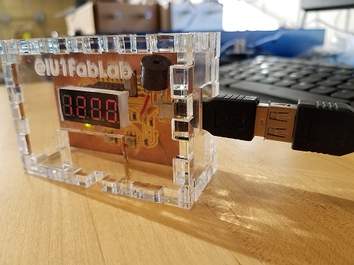
The reason for this design being an afterthought was relizing that the copper PCB’s button controls are more difficult to use inside of the casing compared to the throughhole circuit. I elevated simple rectangle shapes to the specific size so they could fit snug inside the lasercut slot while gluing them to the SMD buttons.
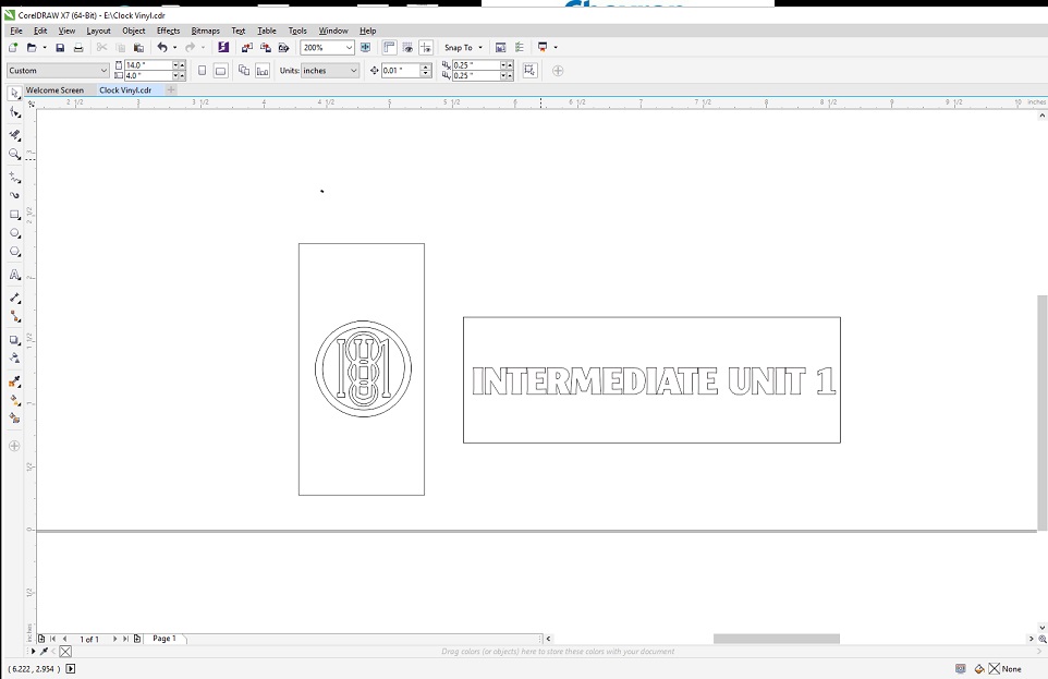
Vinyl Cut Labels
Adding the vinyl cutter was also a last minute decision to incorporate more processes into my design while getting it to stand out a little more. I used CorelDRAW to utilize its TEXT tool and manipulate it to have a hairline stroke with no fill, to then cut from vinyl material (Pen Force = 120 Gram-Force).

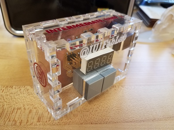
Finished Products:
Original Through-Hole Design
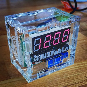
Converted to Copper Milled Design + Added Features (3D Printed Buttons/Vinyl Labels)