Week 13:
Input Devices
Board design
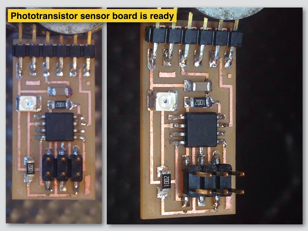
The final project of mine requires sun light sensing and that lead me to choose the phototransistor sensor for the assignment.
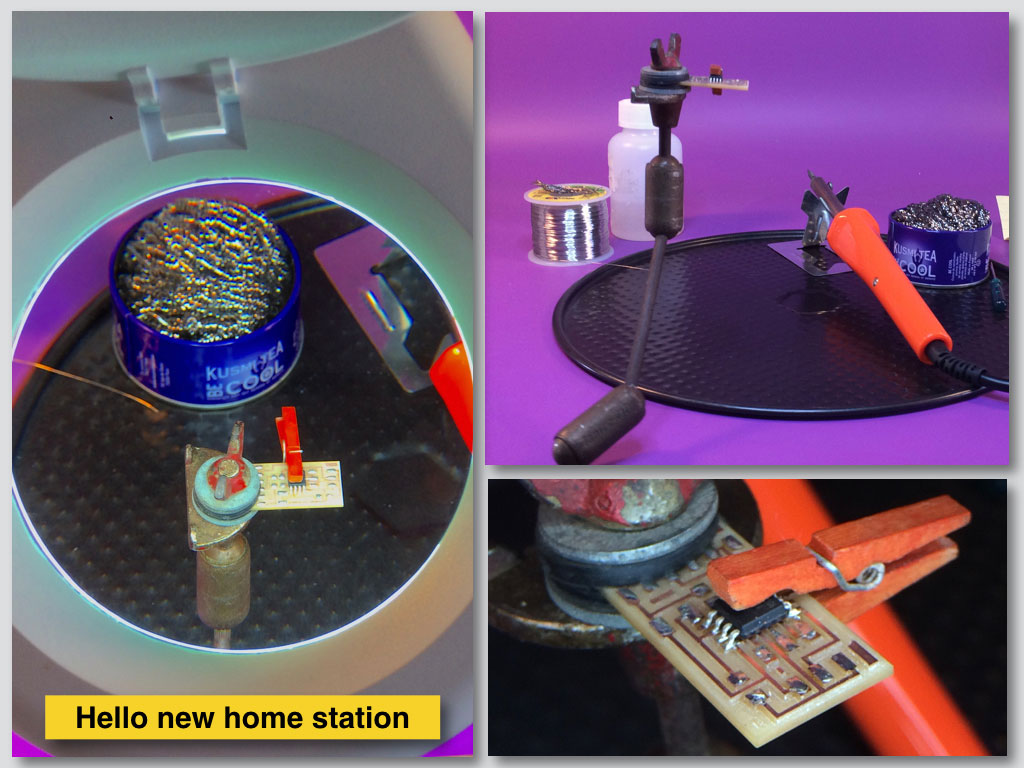
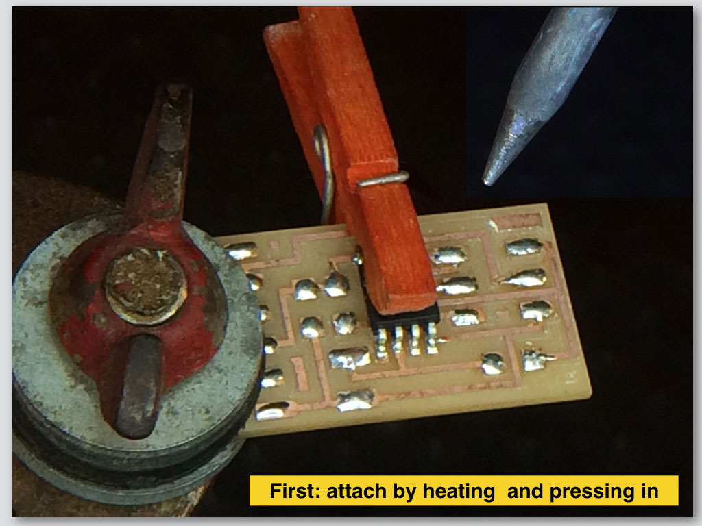
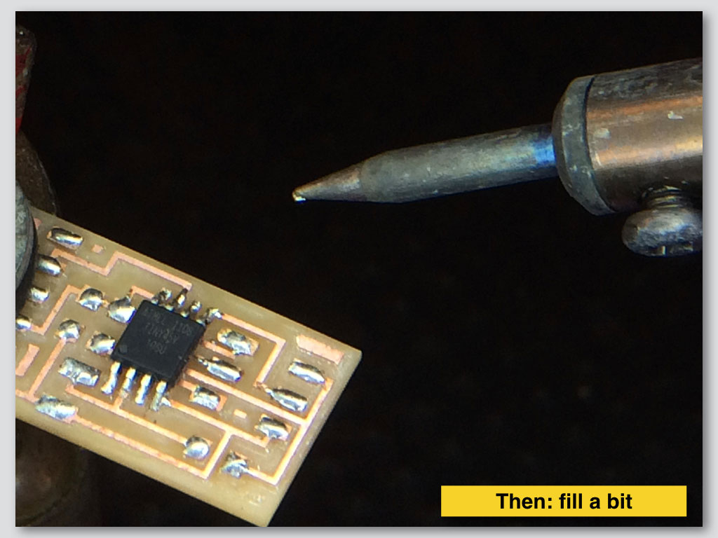
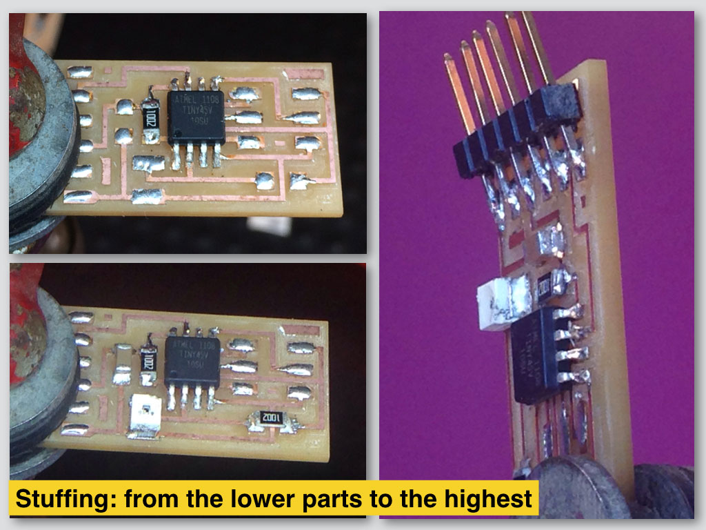
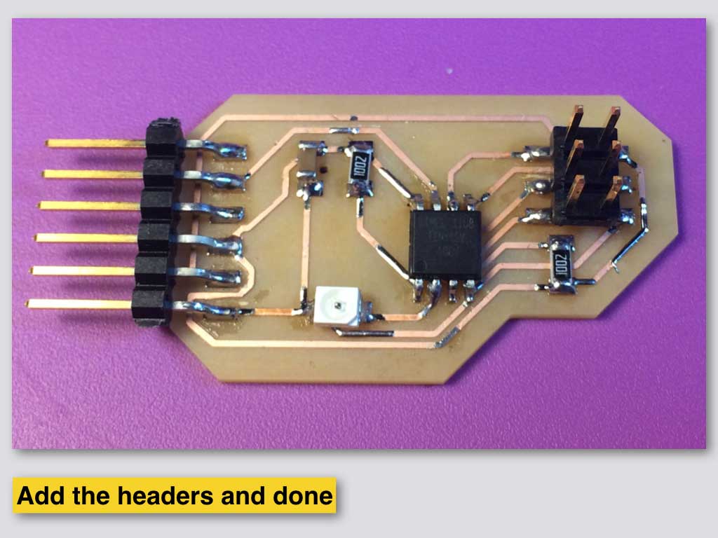
PCB fabrication
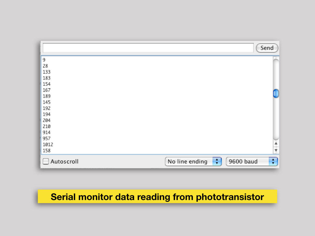
Programing from terminal
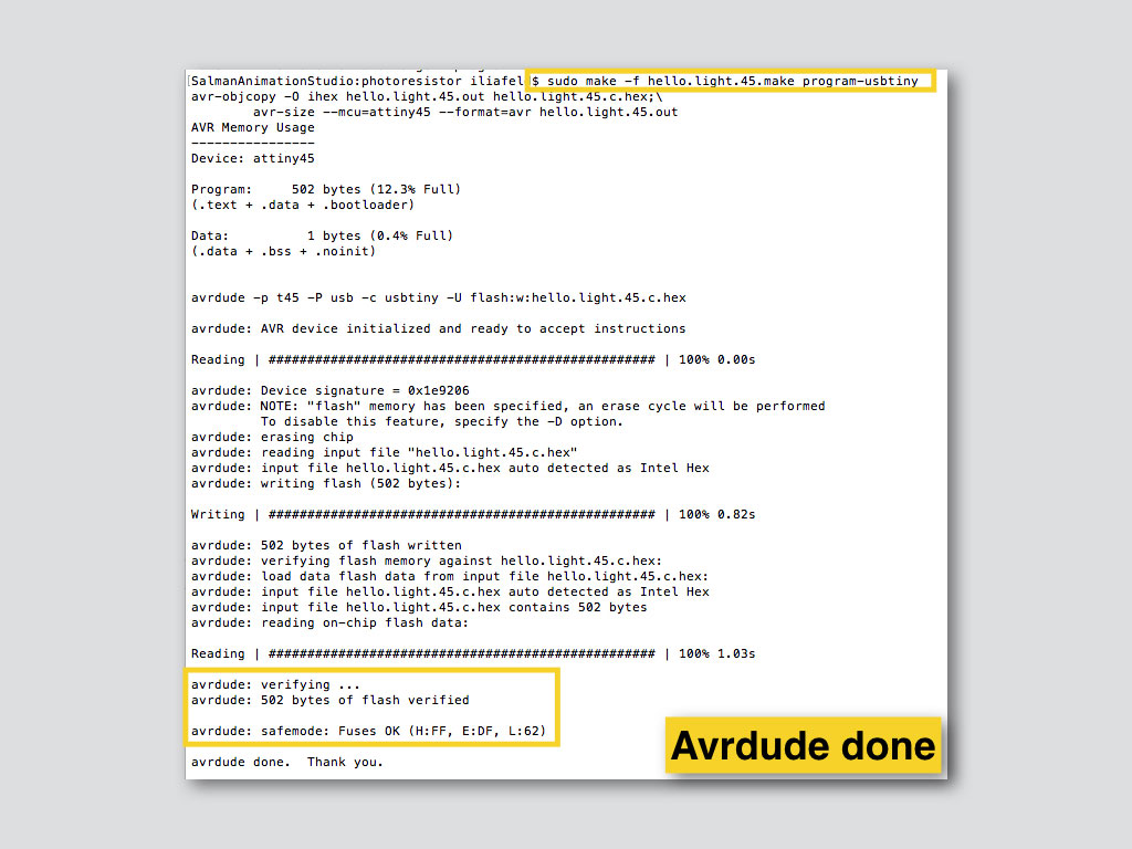
After this step I did not figure yet how to run the serial output to see the sensor data. I installed phyton programm with serial out put but still could not compile/run all of it togather, not even with Xcode on Mac.
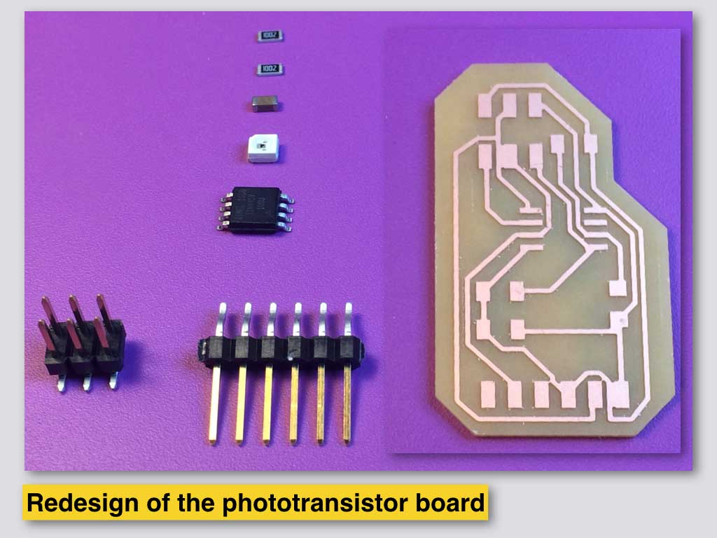
After experience with original board I designed my own version. The same components in different layout.
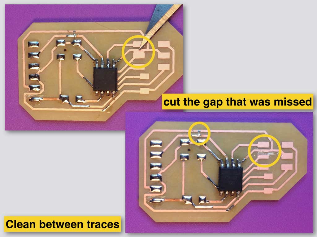
New spacing between traces in my design was bad in few places which I needed to locate and fix.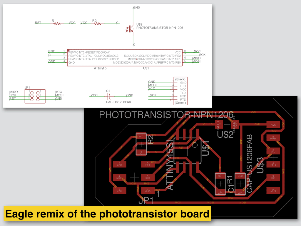


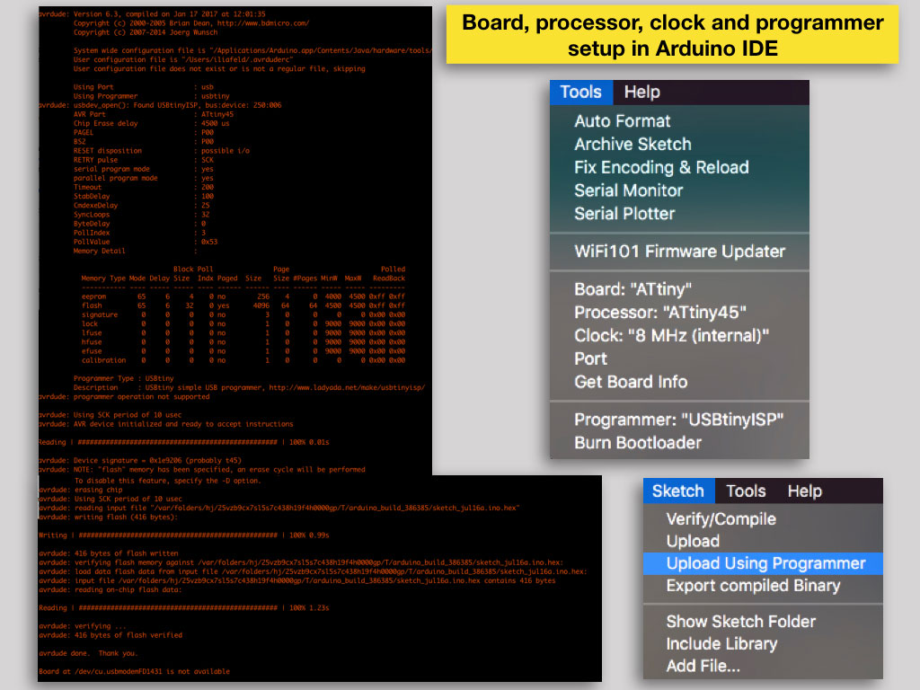
Programming with Arduino IDE
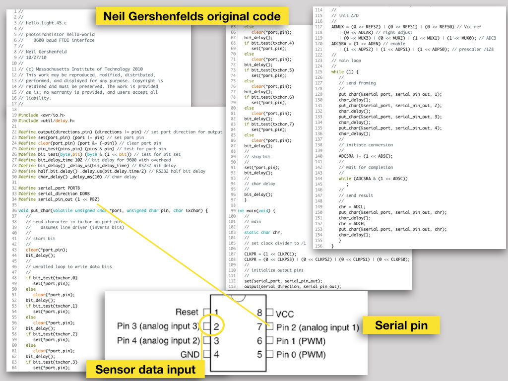
I took the original Neil Gershenfelds code to make the first sensor readings.
Checked and difined the pins crossing the code elements with ATtiny45 pinout scheme and with my phototransistor board shematics.
Checked the code in Arduino IDE, setted the board kind as ATtiny, the ATtiny45 as the processor with intrnal 8MHz clock, the right programer type.
After that I Burned Bootloader on the processer to be sure that the chip and the the board are funtional.
Only then I uploaded the code from Sketch menu with "Upload Using Programmer" command.