Week 10:
Output Devices
Remake learning
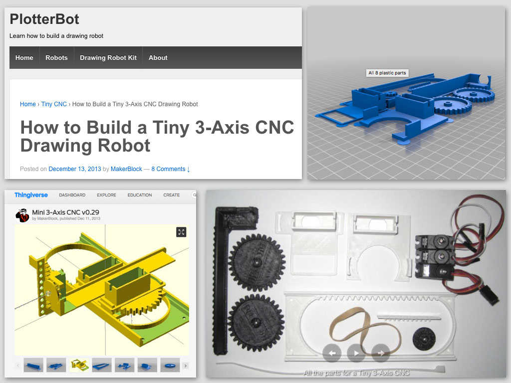
My is plan to make two turnable axises in my final project and also as a part of our group machine building assignment, I decided to remake first some others similar plotter bot project.
This mini plotter has the complexity pretty close to what our needs are.
All of them are based on the same basic principe: CNC G-code concept of axis drive.
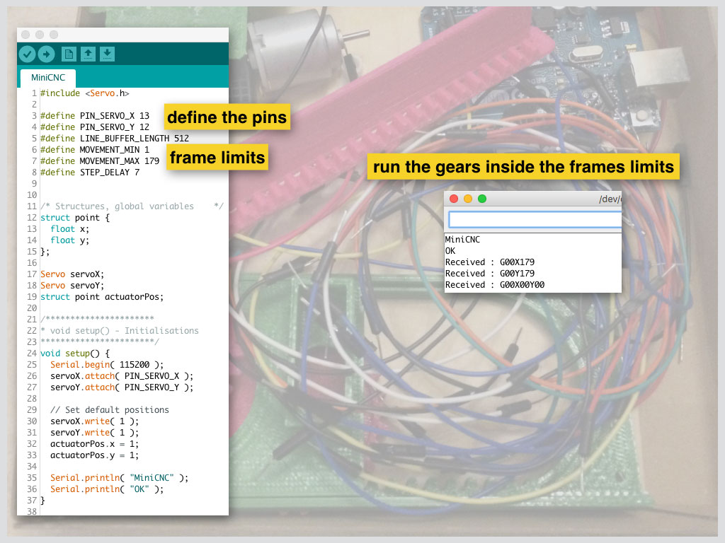
Mid-time my programming and electronics skills still have a lot of room for improvement. The tool for the mission was arduino in my case, so I tried to maximize my controlling skills. I found few different codes here: for shape drawing and also to test servos running in different axises.
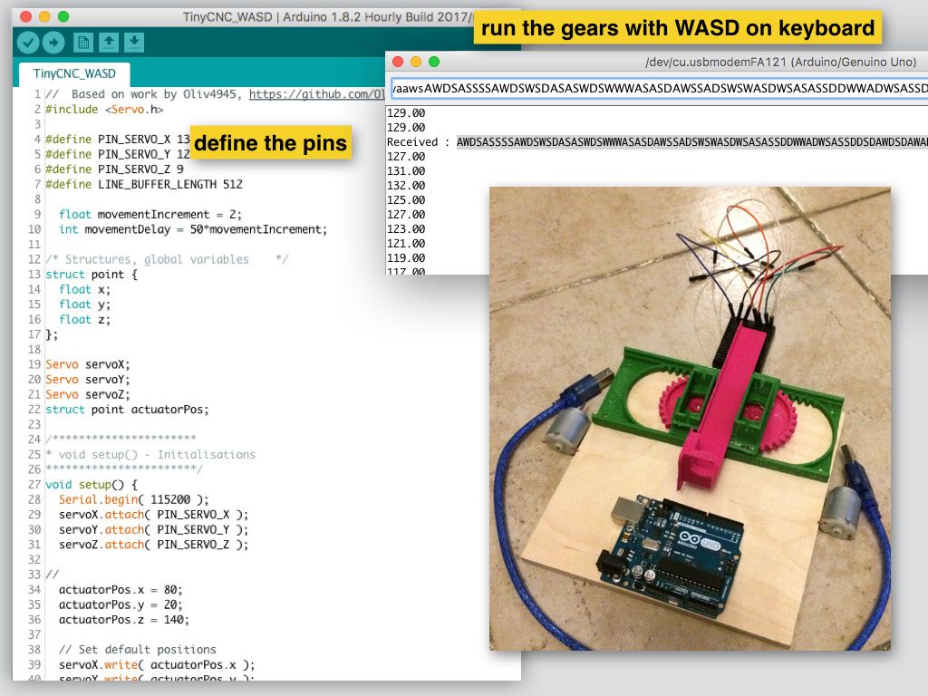
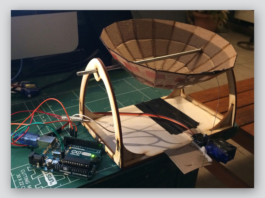
Here is video that shows my first attempt to run both of the axises together and each one of them separately, in both directions.
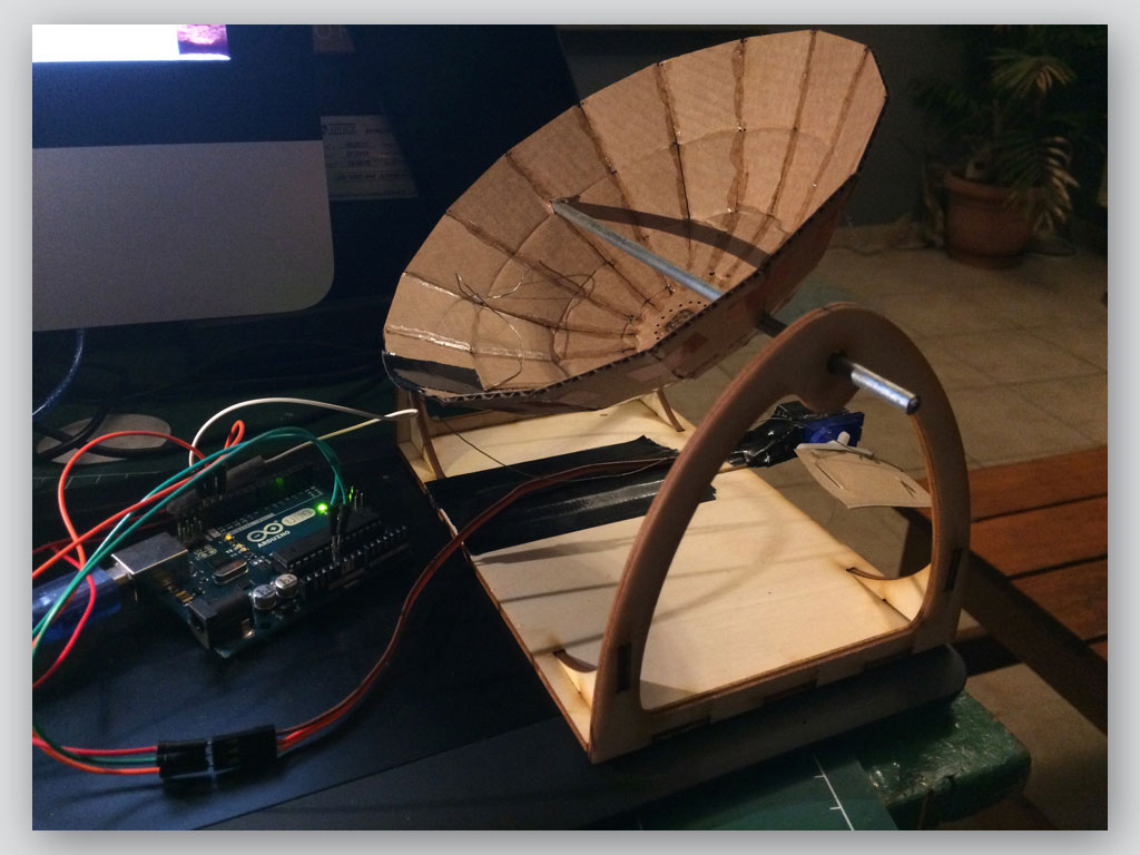
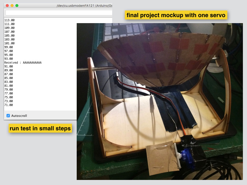
At the second video I run the code that allows to print out motion in each direction for each servo. I used just one of them hacked on final project mockup to show how the solar dish turns around one of its axises.
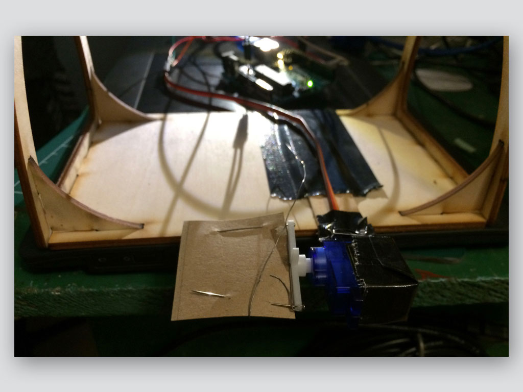
During the work I had many connection issues which made me to give up on the bread board and I made T-Jumpers to solve them.
Design for my own servos board and fabrication
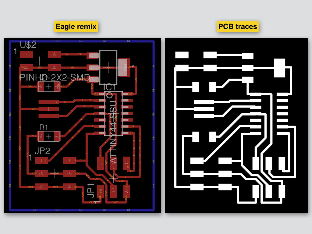
Board logic
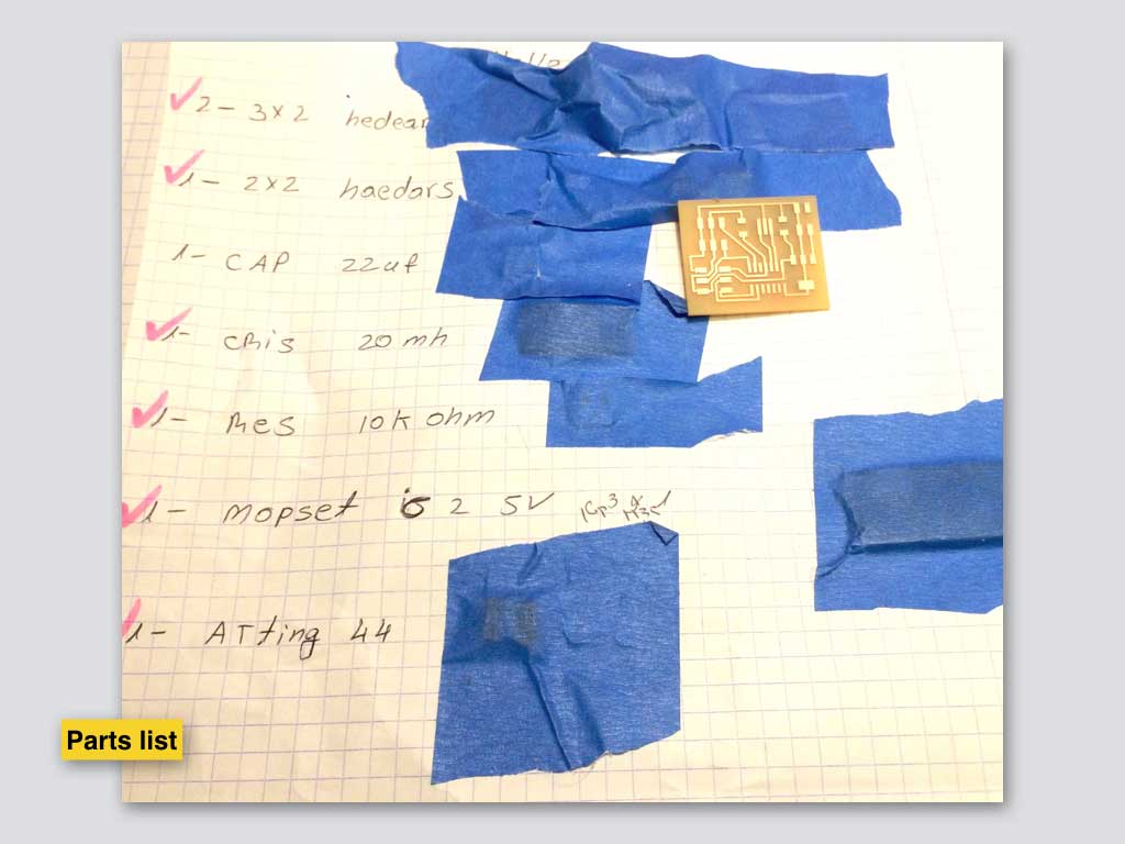
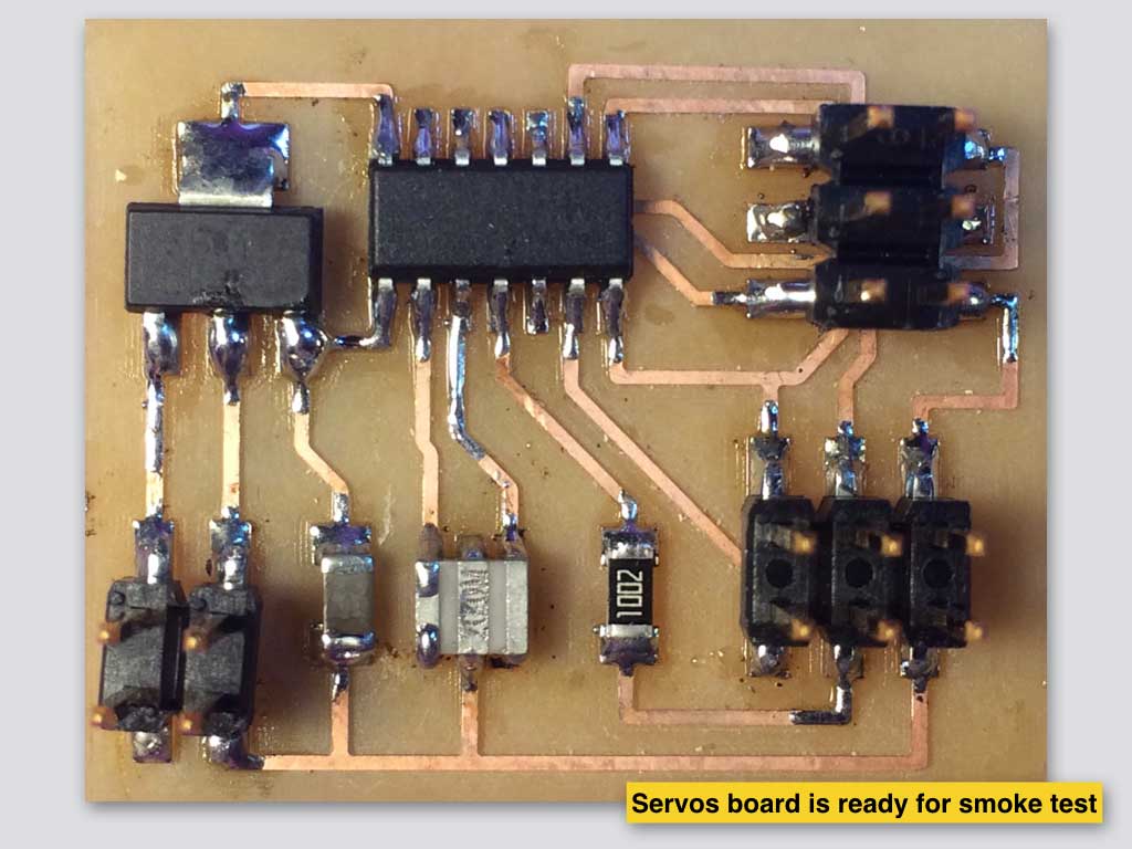
There are three headers on the board. One is for programming(2*3 pins), second is devided and sharing both of the servos. The third one (2*2 pins) for external power. It has ATTINY 44 microcontroler, external 20mh clock, 22uf capasitor, 10k resistor and regulator for external 5V power limitation.
Parts
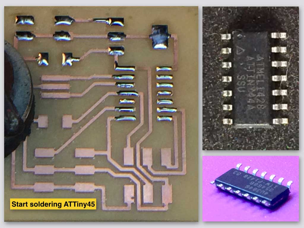
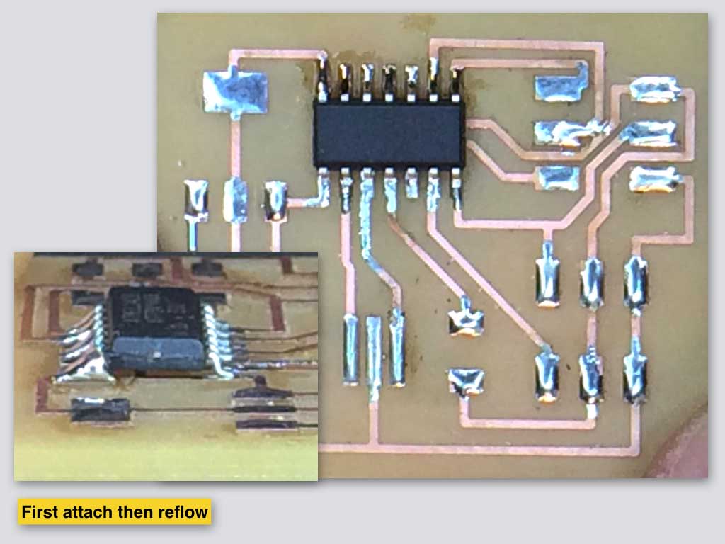
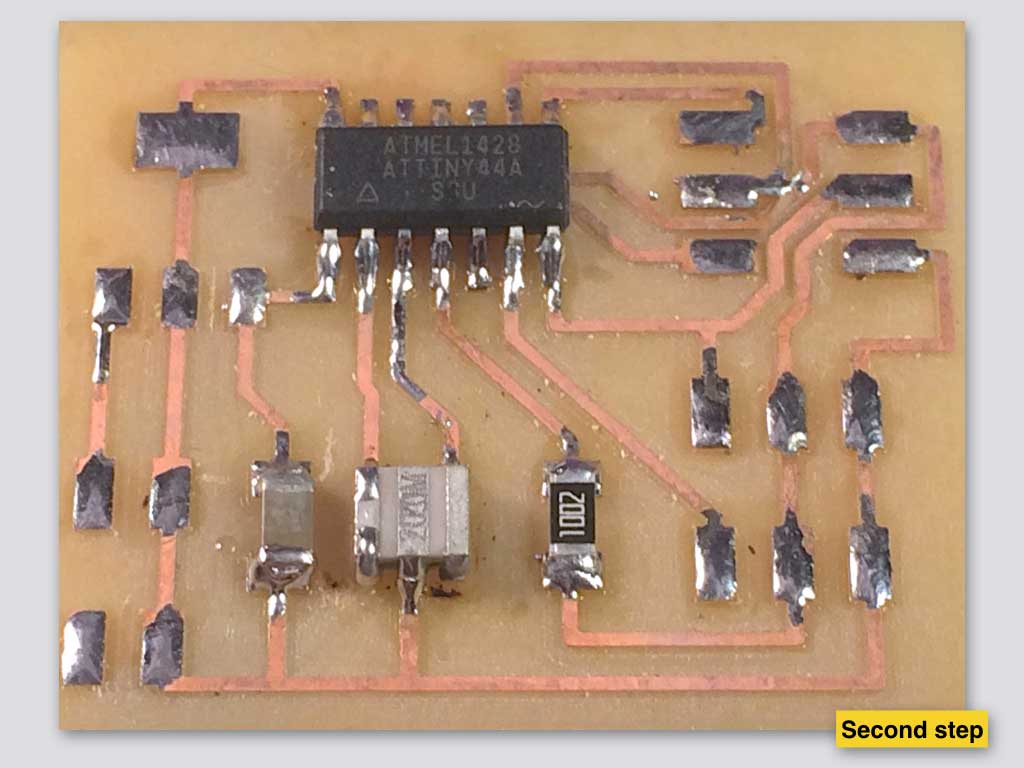
Soldering
Programming
After I tested the connections on the board with multimeter and every thing looked clean I tried few times to programm it with USBtiny programmer in Arduino IDE without any success. I only Burned Bootloader which was my indication that the board is ok but I couldn't upload the sweep servo arduino example or any other code to it.
My guess is that I made a mistake in regulator alignment at the Eagle design, at the schematic stage. Seems I messed with regulators out pins. My attempt to frankenwire it was not successfull. There is a need to redesign the board.