Week #3: Computer-controlled cutting
The tasks for the third week were:
- Design, make and cut a parametric press-fit construction kit
- Cut something on the vinylcutter
Our
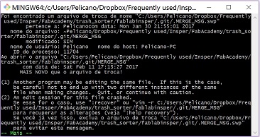
week began with a little incident: a colleague chose some wrong options
while using Git Bash and all our websites returned to their older
versions. To me, this was not a big deal, since I always keep an up to
date local copy of all my website files (thanks for the tip, Kenzo!).
Something curious, though. During the pull, I got this message:
But, after that, everything seemed ok.
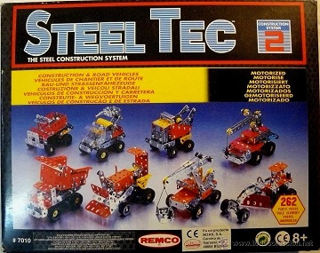
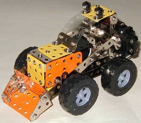
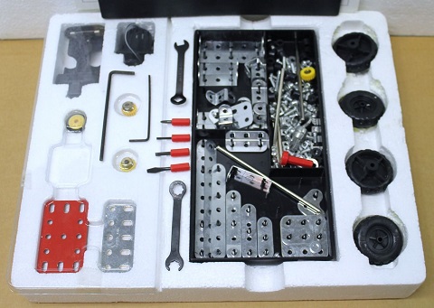
As for our task, after some thinking, I recalled an educational toy I used to play with when I was a kid: Steel Tec.
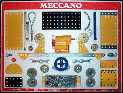
As our instructor Kenzo pointed out, there's a very similar toy called Meccano:
The
one I had, Steel Tec, was comprised of different sizes of plates
with holes, such that you could attach each other with nuts and bolts
and make different vehicles, like the bulldozer shown above. It also
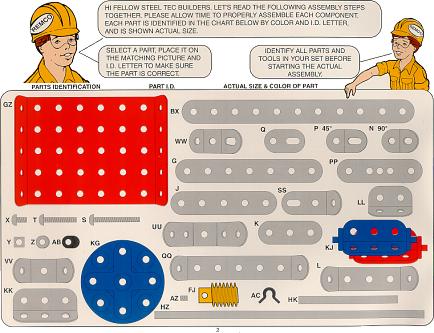
came with some tools and an instruction manual:
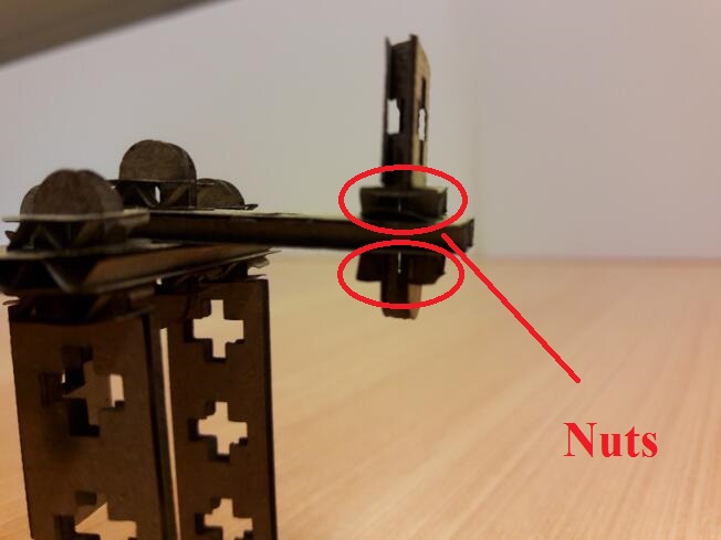
My idea for this week's task was to mimic this toy with cardboard, using some kind of press-fit nut and bolt system.
Before
doing that, I had to learn how to produce a file that is compatible
with the laser cutter software. At Insper Fablab, our laser cutter
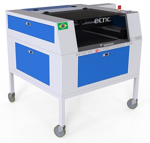
is an Epilog Laser Mini, which I already knew how to use; but, it broke down
just as our classes starded. So, after some phone calls (thanks again,
Kenzo!), some kind people from FabLab Educação lent us their laser
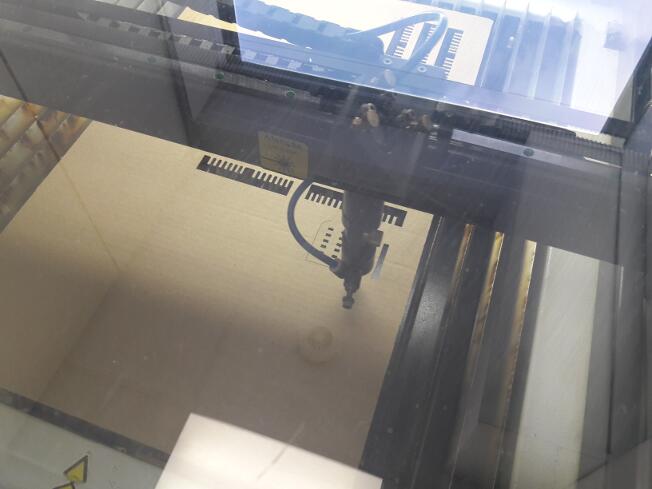
cutter, an ECNC L-560, as shown below.
This model of laser cutter uses UD5 files as source, and these files are generated by a
software called LaserCAD, which in turn is fed by .DXF files. I am used
to working with Inkscape, which is able to generate these files, but is
not able to do parametric modelling. So, I chose Creo Parametric for
the task.
When it was our turn to use the laser cutter, we
started by the group work part of our assignment, which was
to create different types of press-fit joints in order to
understand how the machine works, e.g., how it deals with fractions of
milimiters and how wide is its kerf.
We used two softwares for
this task: Fusion360 and Creo Parametric 4.0. With the first one, we
designed pieces with small differences: chamfer, fillet etc. This is what we got:
By
doing that, we learned how to take the kerf into account and we also
learned that some cuts can greatly improve the assembly of the pieces
together.
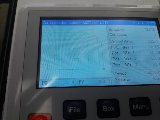
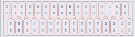
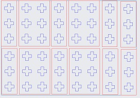
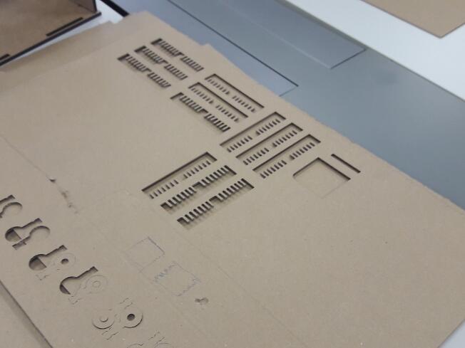
Then, with the help of Creo Parametric 4.0, we cut
rectangular holes with small differences in height and width (file here; password abc123). We drew
15 holes in 3 columns and 5 rows, as can be seen on the machine display:
In
the first row, all the rectangles have a height of 2.6 mm; in the
second, 2.7 mm, and so on, meaning that, in the last row, all the heights are of 3.0 mm. In the first column, the width is 4.9 mm; in the second, 5.0 mm and, in the third, 5.1 mm.
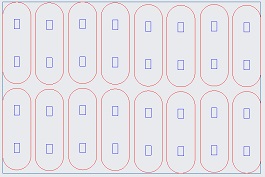
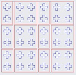
This is the cutting itself:
The
reason why we did this second test was to answer a simple question: if
the male piece is x mm wide, should the female piece also be x mm wide?
The answer we got was: no!
When we tried to fit together two 5
mm wide parts, the assembly was quite loose. On the other hand, when
trying to fit a 5 mm wide part into a 4.8 mm wide part, the fit was
perfect. That was an important lesson: don't forget to take 0.2 mm out
of every female part.
After the tests, I proceeded to the
individual part of the assignment. Since the carboard thickness could
vary, I had to design the parts parametrically, which is quite
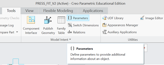
straightforward to do in Creo Parametric 4.0. To do that, we first create the parameters by clicking on Tools -> Parameters.
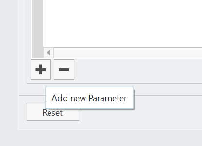
Then, click on "Add new Parameter":
After that, we have to give the new parameter a name and a value:
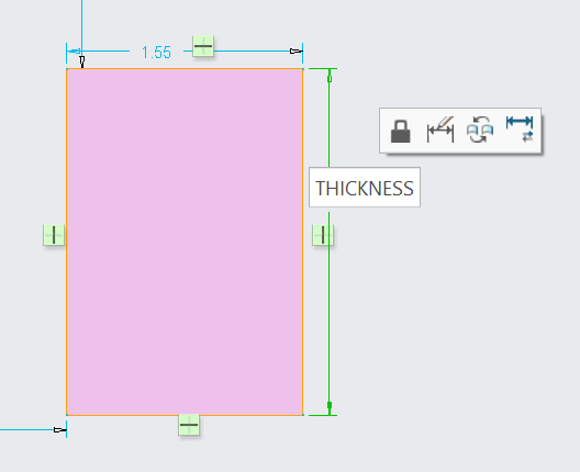
Then,
we proceed to the design. For example, if you want do draw a rectangle
with, say, height THICKNESS, first you draw the rectangle without
specifying them. After that, you double-click each dimension and
replace the value by the desired formula:
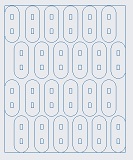
At first, I designed two
types (first two figures below) of bolts and the nuts (the last figure
below). The first bolt can hold together 2 layers of cardboard; while
the second one can hold 3 layers.
As
soon as I finished designing those bolts, I realized the cutting could
go terribly wrong: what if the contour of the bolt is cut before the
hole? If this were to happen, maybe the bolt would detach from the
board and the holes wouldn't be cut (and the laser would be activated
for nothing during those cuts).
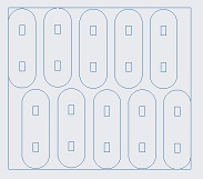
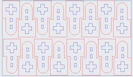
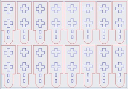
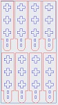
So, after talking to Kenzo, I
confirmed that the laser cutter could be instructed to cut lines of
specific colors in a certain order. Then, I went back to my designs and
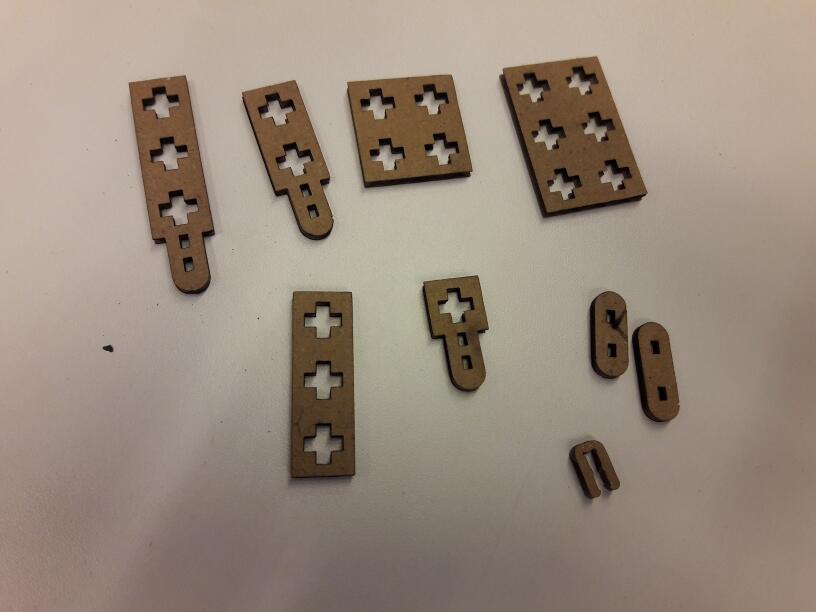
chose the color blue for the first batch of cuts and the color red for the second batch, as can be seen below. I designed 9 kinds of pieces (not counting the nuts), which can be seen below.
As
expected with computers, things did not work out quite right from the
beginning. The first problem was that the .DXF file generated by Creo
Parametric was not compatible with LaserCAD, freezing the program
instantly.
So, I tried opening this .DXF file with Inkscape and
saving as another .DXF file. This time, LaserCAD was ok with the file,
but there was some misconfiguration regarding the units and the drawing
was interpreted by LaserCAD as really, really small. Then, I tried
tweaking the configurations, but to no avail. I just could not seem to
get LaserCAD to interpret the dimensions correctly.
After some
thinking, I tried saving the drawing in Creo Parametric as a .PDF file.
Then, when I opened it with Inkscape and saved it as a .DXF file,
everything worked out just fine.
This
step also helped with something else: when you copy multiple instances
of a parametrized object in Creo Parametric, the software gets
exponentially slower. So, if I open one instance of the object in
Inkscape, I can copy it as .PDF, which is much faster.
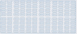
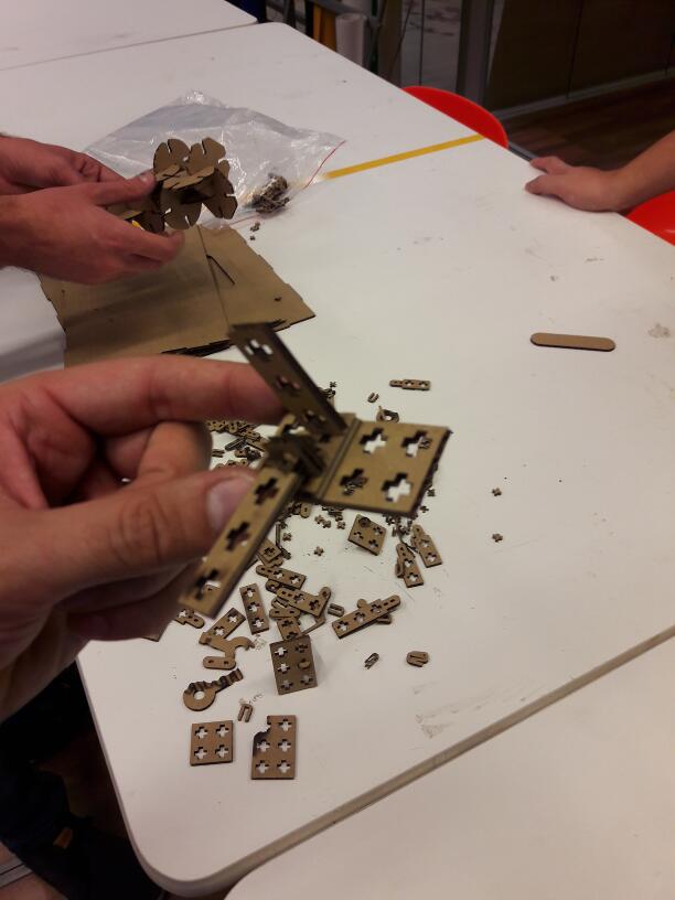
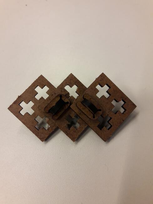
Then, I proceeded to the cutting. The pieces are show below (files here, password abc123).
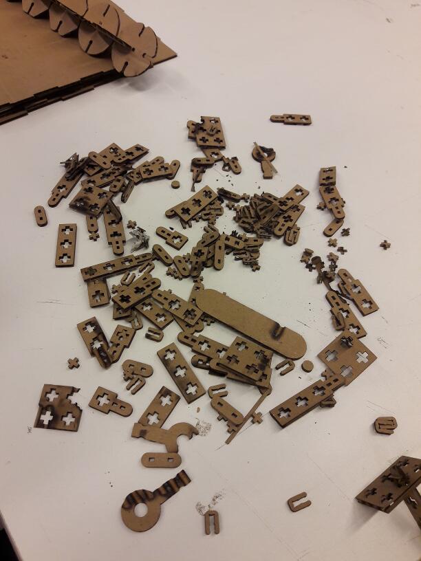
As
can be seen, some pieces were burned. That happened because the machine
was being shared and, in between files, someone changed the laser
power. But, that's ok, as I still got lots of pieces to play. This is
an example of assembly, just to see if the pieces did, in fact, fit
together:
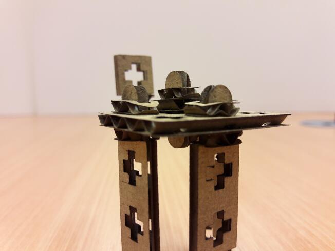
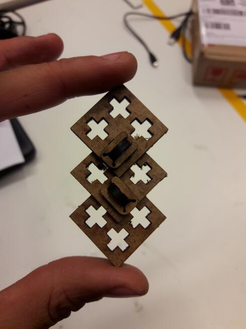
Here you can see another example, using the pieces properly:
As
expected, my toy did not work quite so well. I forgot to take into
account that de corrugated cardboard is not solid and, because of that,
the pieces were extremely weak. So, after the first assembly, the
pieces weren't of much use for a second assembly.
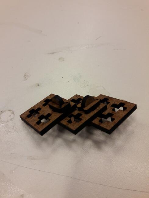
I was
going to try again with wood, but our laser cutter was not working at the moment, so
this idea had to be put on hold for a while. After the machine was fixed, I tried againd and the results were much, much better:
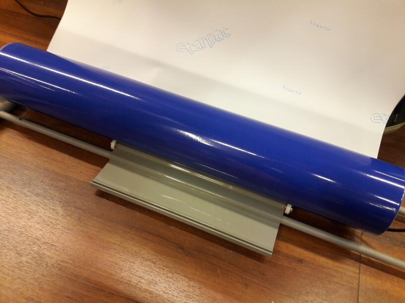
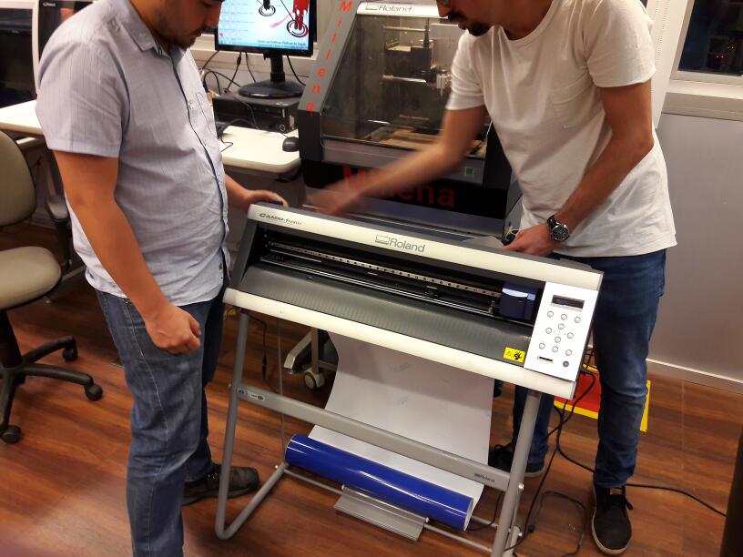
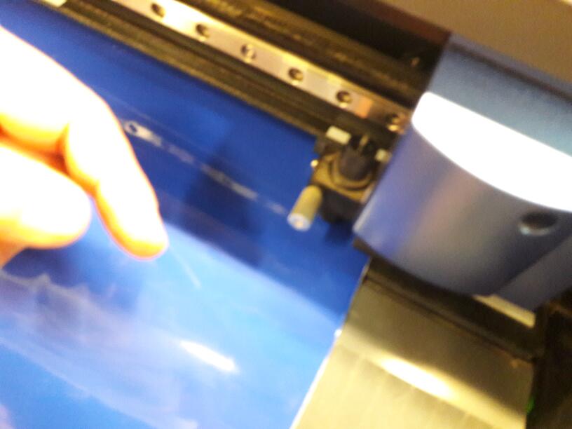
As
for the vinyl cutter, our instructor Kenzo showed us how to operate the
machine, which can be seen on the three images below, and then asked us
to cut a sticker.
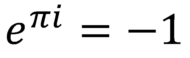
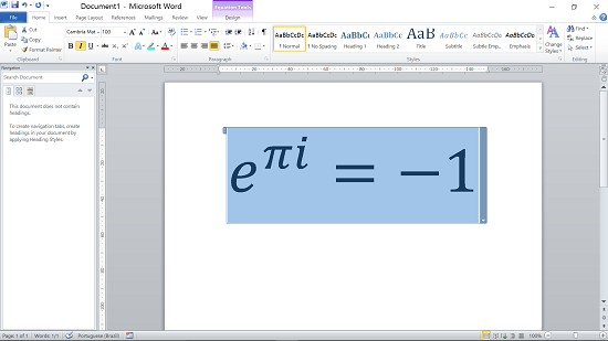
Since
I wasn't feeling particularly creative at the moment (all the
creativity was spent on the press-fit project), I decided to cut an
equation, instead of a figure. The equation I chose is a direct
application of Euler's formula (for complex numbers) and is considered
one of the most beautiful in Mathematics, since it shows two popular
irrational constants, the imaginary unit, the equal sign, the minus
sign and the number 1:
To design it, I simply typed it on Word Equation Editor, chose a really big (100) font size and exported the file as a PDF:
Then,
to generate the .EPS file which can be interpreted by the vinyl cutter,
I imported the file into Gimp and exported it as a .EPS.
You acand find both the .PDF and the .EPS files here (password abc123).
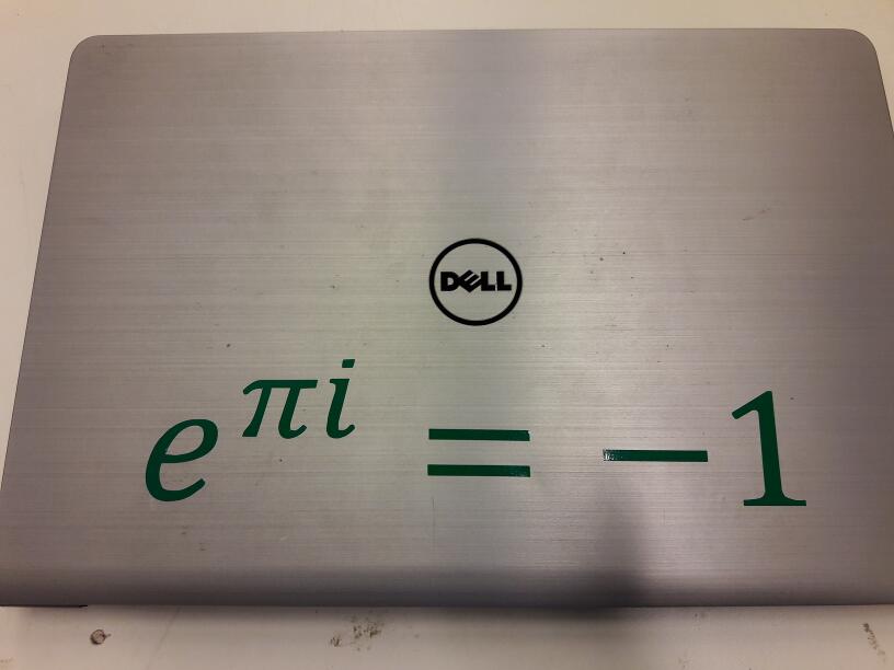
This is what I got for the final result:
And that's my progress for the third week! Next step: electronics production!
All the files that were mentioned in this week progress can be found here.