Output Devices
This week's task was to add an output device to a microcontroller board you've designed and program it to do something.
To begin with this task, I took a deeper look to my final project. For 2 - 5 years old kid, it's so interesting and so exciting to have lights and sounds. They capture his attention and help him to discover the world.
So, my main idea was to develop A light pattern that capture the kid attention and also when the piece is in the right place, a certain LED would be ON and some sounds.
For here, I wanted to try the light pattern mainly. It has a similar idea of this video.
The Board:
I developped the schematic on Eagle.

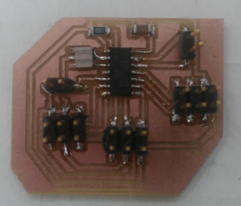
And Then produced the board.

Getting the traces and the borders done, It's now time for Milling!.
This is how it looked at the end.

Now, time to Stuff the board with the components.

Programming The Board:
I udes Arduino IDE for Programming the board.
The Code:
                        int led1 = 11;
                        int led2 = 10;
                        int led3 = 9;
                        int led4 = 8;
                        int led5 = 7;
                        int led6 = 6;

                        void setup() {
                            pinMode(led1, OUTPUT);
                            pinMode(led2, OUTPUT);
                            pinMode(led3, OUTPUT);
                            pinMode(led4, OUTPUT);
                            pinMode(led5, OUTPUT);
                            pinMode(led6, OUTPUT);
                        }


                        void loop() {

                            int t = 10;
                            for (int i = 2; i<8; i++){
                              digitalWrite (i, HIGH);
                              delay(t);
                              digitalWrite (i+1, HIGH);
                              delay(t);
                              digitalWrite (i+2, HIGH);
                              delay(t);
                              digitalWrite (i, LOW);
                              delay(t);
                              digitalWrite (i+1, HIGH);
                            }

                            for ( int i= 7; i>1; i--){

                            digitalWrite (i, HIGH);
                              delay(t);
                              digitalWrite (i-1, HIGH);
                              delay(t);
                              digitalWrite (i-2, HIGH);
                              delay(t);
                              digitalWrite (i, LOW);
                              delay(t);
                              digitalWrite (i-1, HIGH);
                            }

                        }
Final Project Circuit:
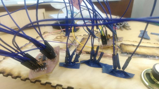
For the Final project, I made a different version of the circuit as I needed through hole LEDs. I replaced the LEDs and the resistors with pin headers to be able to connect the through hole LEDs and I connected the LEDs to 220 Kphm resistors I thought it can go without LEDs but it failed.
Here How it looked like.
And Connecting it to the LEDs
Programming the Final Project Circuit:
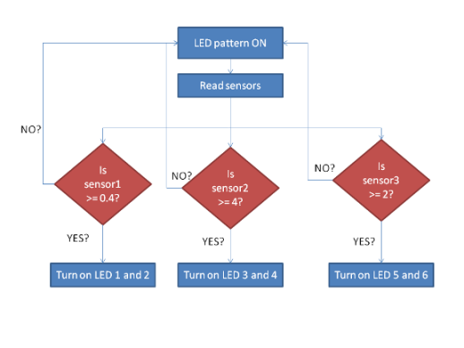
The code of the final project was little different. A bunch of If conditions were added to peform the function of indicating the right piece in place.
The code simply goes like this:
 |
 |
| Every sensor alone | Combinations |
The challenge of the program mainly was in the serial communication, and that explained more in details in the Networking assignment.Yet after solving them, And Here we Go!
Downloads:
1. Circuit Schematics and file.
2. Arduino Code.