- Week 10 +
output devices
Tasks
Introduction
For this week’s assignment, I decided to use a servo motor as my output device. The servo motor is relevant to my final project and so I have chosen it. A servo motor is a special type of motor that can turn a set number of degrees depending upon the PWM signal given to it. Typically in a pulse width of 20ms, a 1500 microsecond pulse would make the servo go to 90 degrees, whereas a 1000 microsecond pulse will make it go 0 degrees, and finally a 2000 microsecond pulse will make it go 180 degrees. But it typically varies a little bit with each servo. It has three pins for connecting to the controller:
- 1. Vcc: It is used to power the motor. It can take from 4.5 to 7V DC power and typically consumes current upto a few hundred milliamps.
- 2. Signal: It is used to give a PWM signal to the servo motor’s controller. The width of the high pulse controls the angle of the motor.
- 3. GND: It is used as a sink for the current sourced by the Vcc pin
lEARing resources on SERVO
Design Workflow
Here’s how I designed the board for the output device using a servo. The steps are very similar to the electronic design week so I’ll be covering relevant steps only.
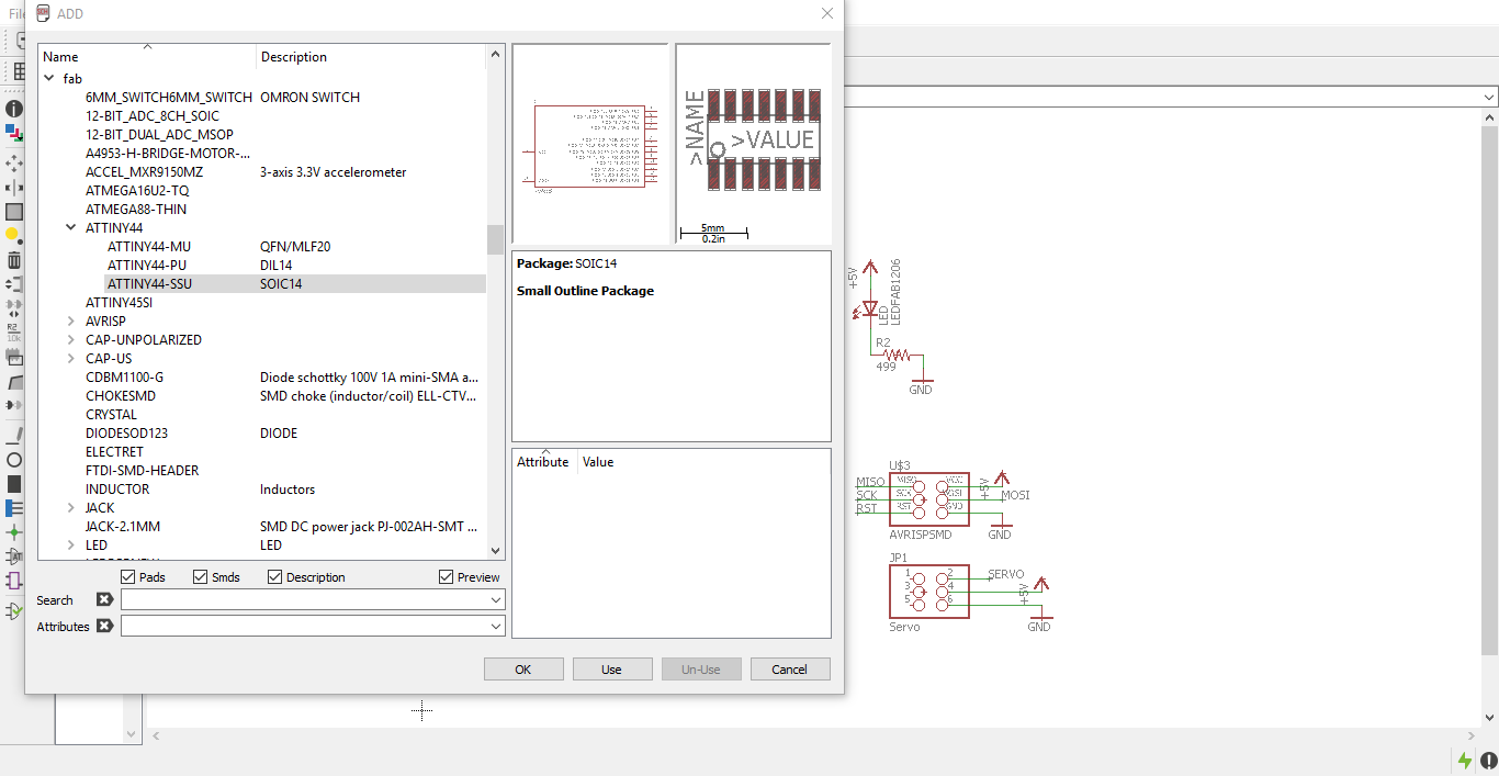
Step 1: Add components
First of all I added all the relevant components for the board to the schematic page and started connecting them as needed.
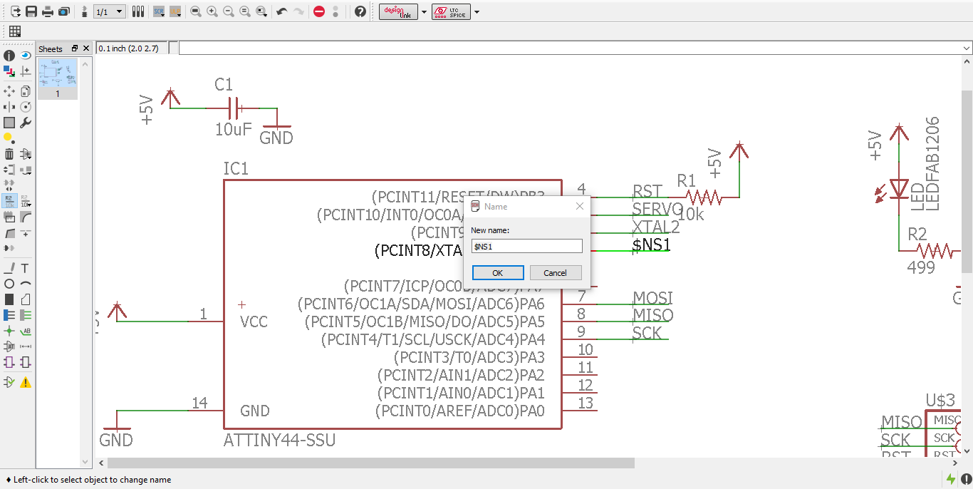
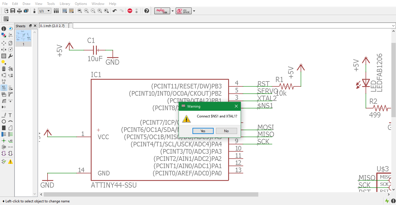
Step 2 -3: Net to pin
Here is a series of screenshots demonstrating the way to connect various pins with each other using net labels.
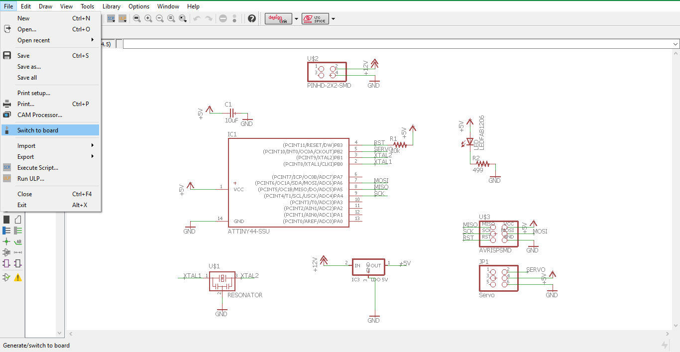
Step 4: Switch to board
Once all the connections are done and verified by the ERC, I proceeded to File > Switch to Board.
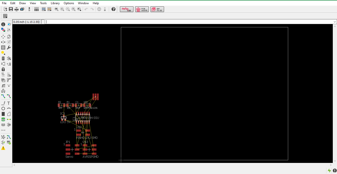
Step 5: Board Created
The board layout window was generated. From then onwards I proceeded to rearranging the components and resizing the pcb to my requirement.
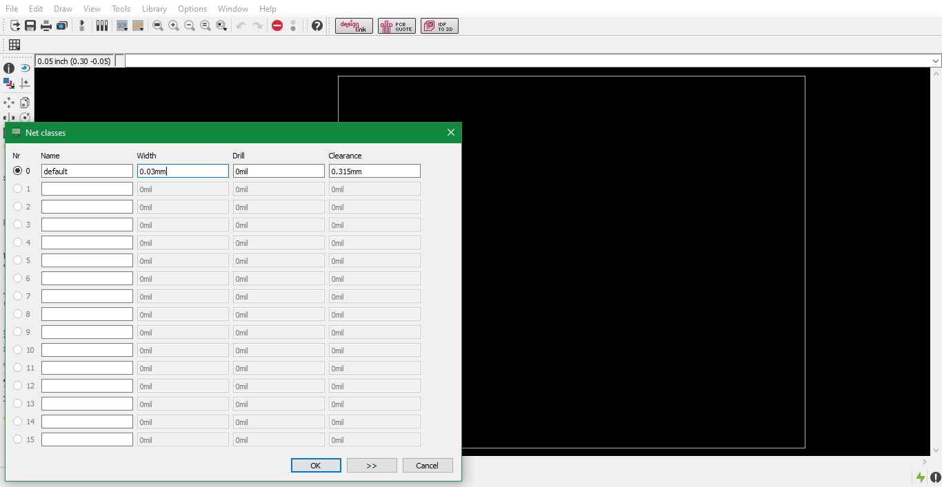
Step 6: Edit Net classes
I edited the net classes to the following settings:
| Width: | Clearance: |
|---|---|
| 0.03mm | 0.315mm |
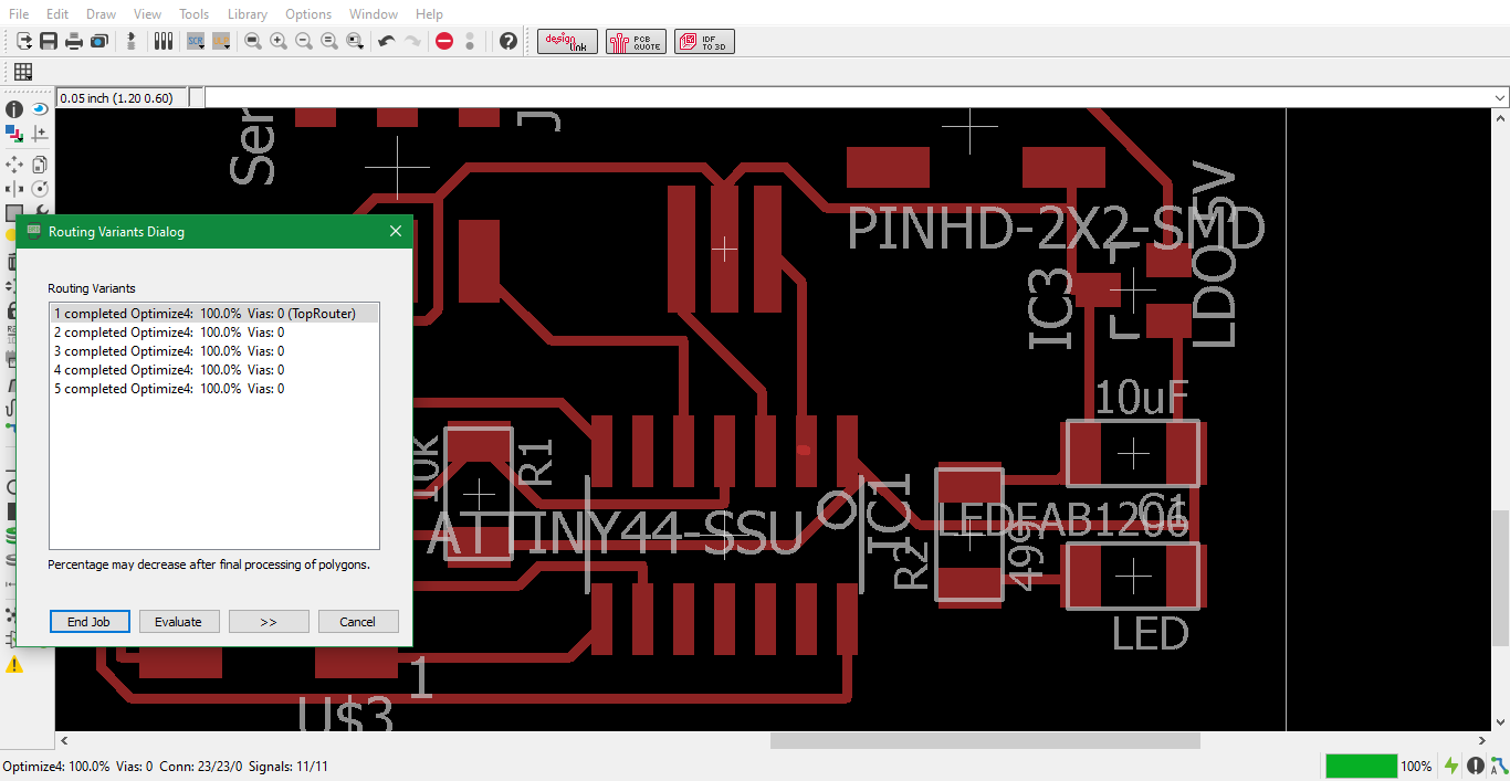
Step 7: Autorouting complete
After setting the net classes, I autorouted the traces and as always, the TopRouter had the most compact circuit design.
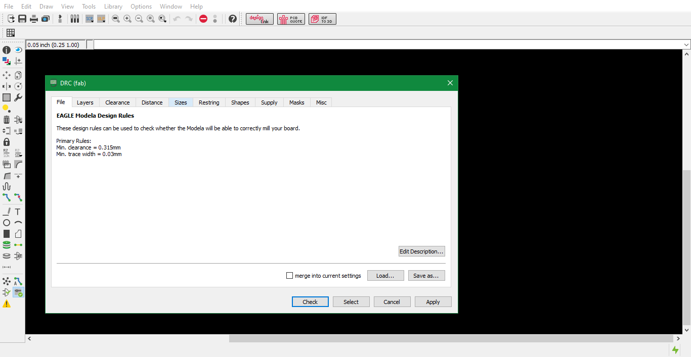
Step 8: DRC check
After finishing the AutoRoute traces, I conducted a DRC to check if my design is valid and found no errors.
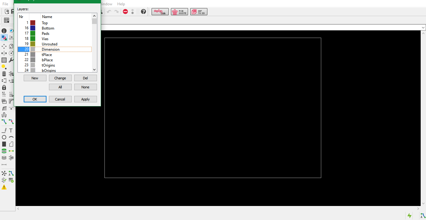
Step 9: Saving interior as png
I then proceeded to creating the PCB Fab files for the interior of the board
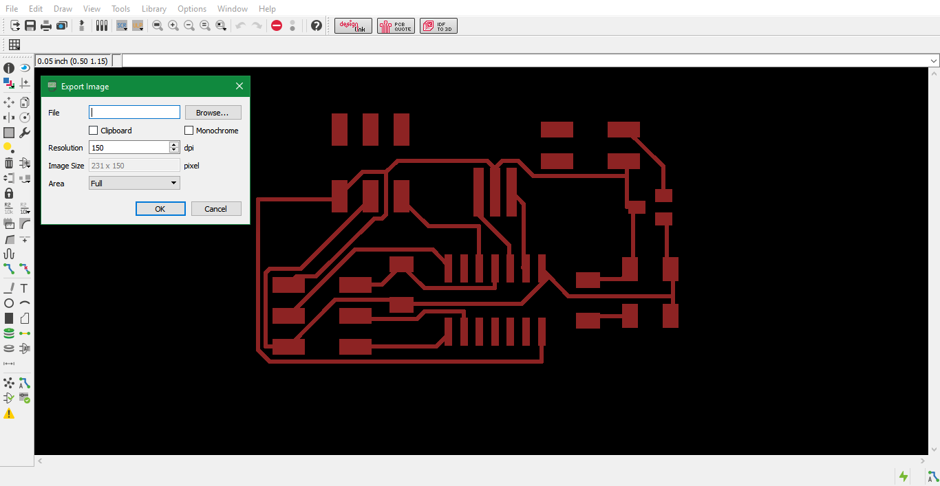
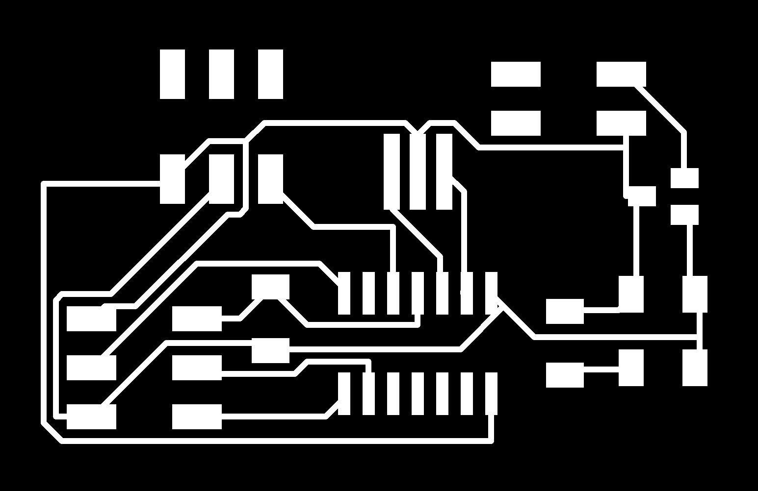
Step 10: Saving traces as png
I also created the PCB Fab file for milling the PCB traces and exported it as a monochrome png image.
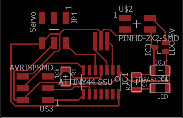
Servo Details
Servo Traces
Milling workflow
After designing the board, it was time to mill it. I again used the fab modules to operate the micro-milling machine similar to electronics design and production weeks.
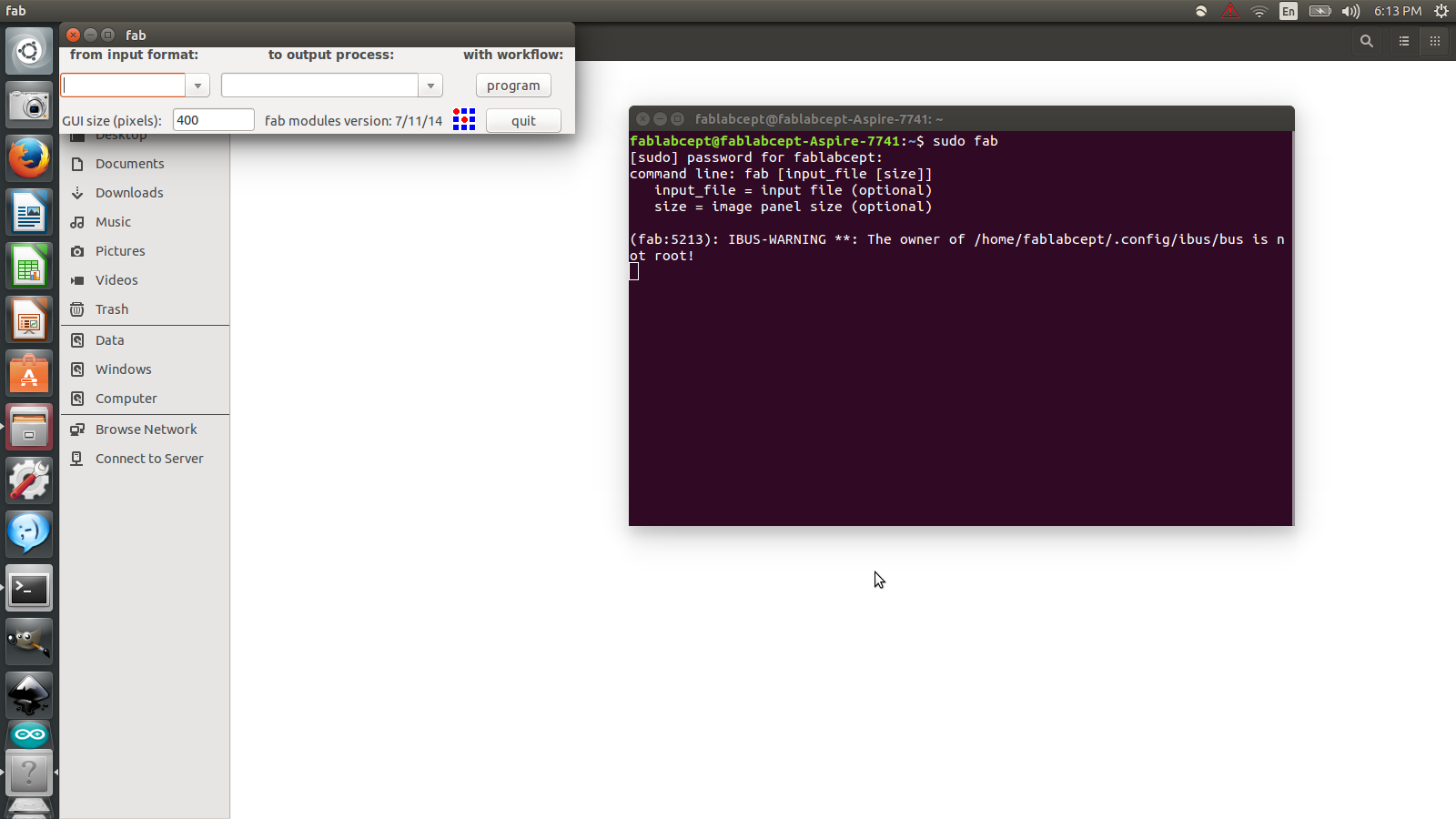
1. First we launch a fab modules window by typing “sudo fab” in a fresh terminal window. This opens a window asking the input format and output process.
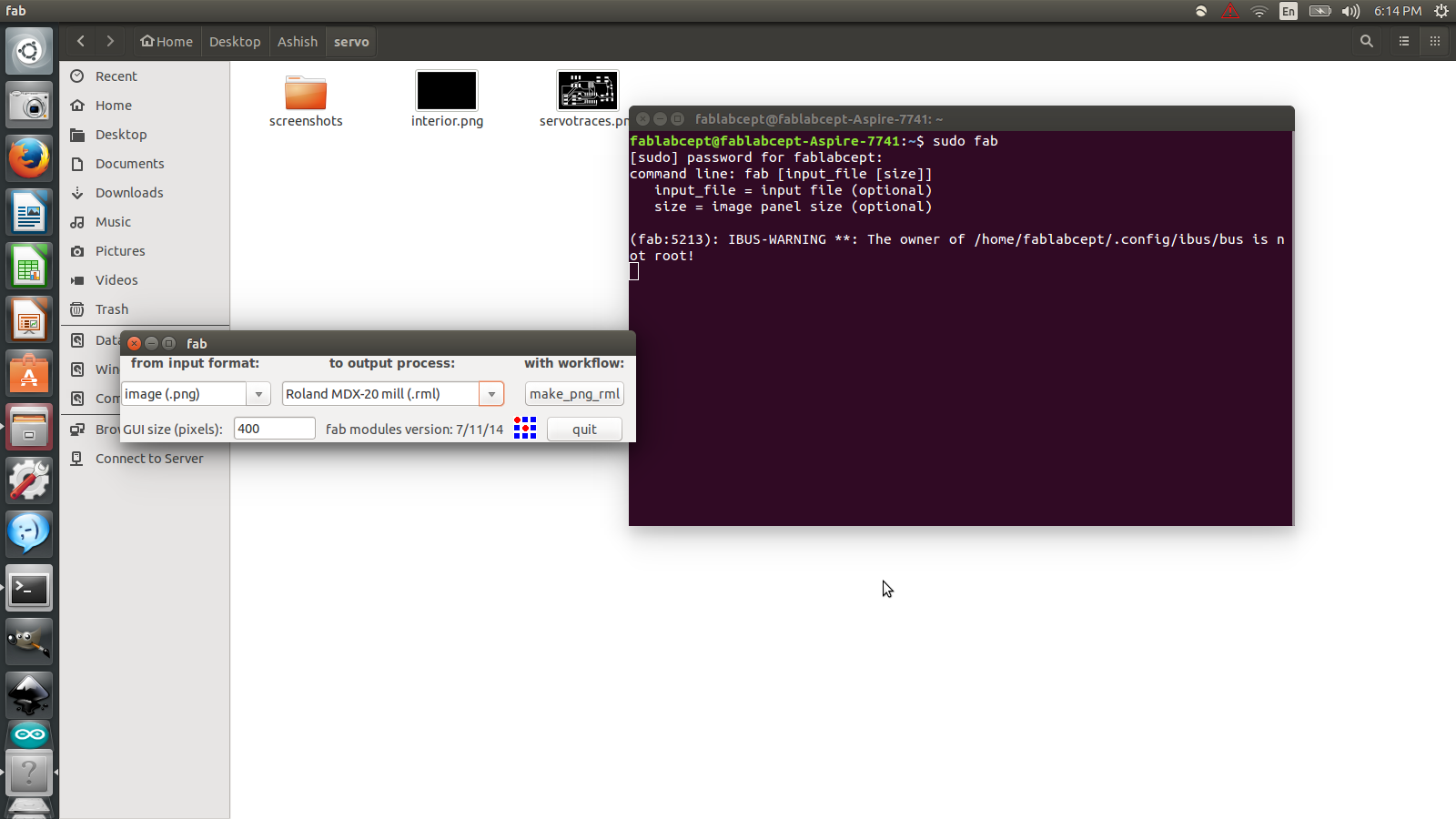
2. I chose input as image (.png) and output process as Roland MDX-20 mill (.rml) and pressed “make_png_rml”
3. This opens another window that is the start window of the module. Here settings can be edited as per requirement.
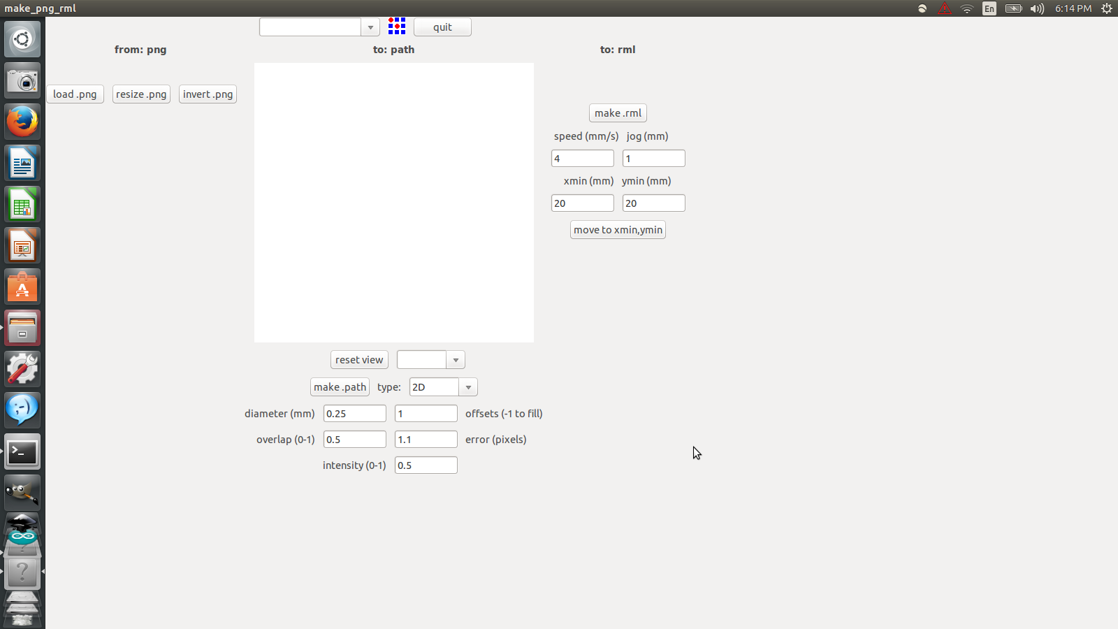
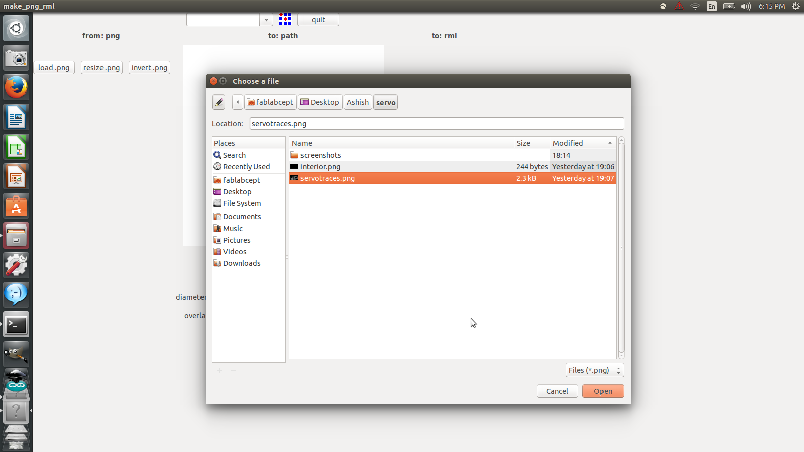
4. I loaded the traces file in the module by clicking on load .png and navigating to the position of the file.
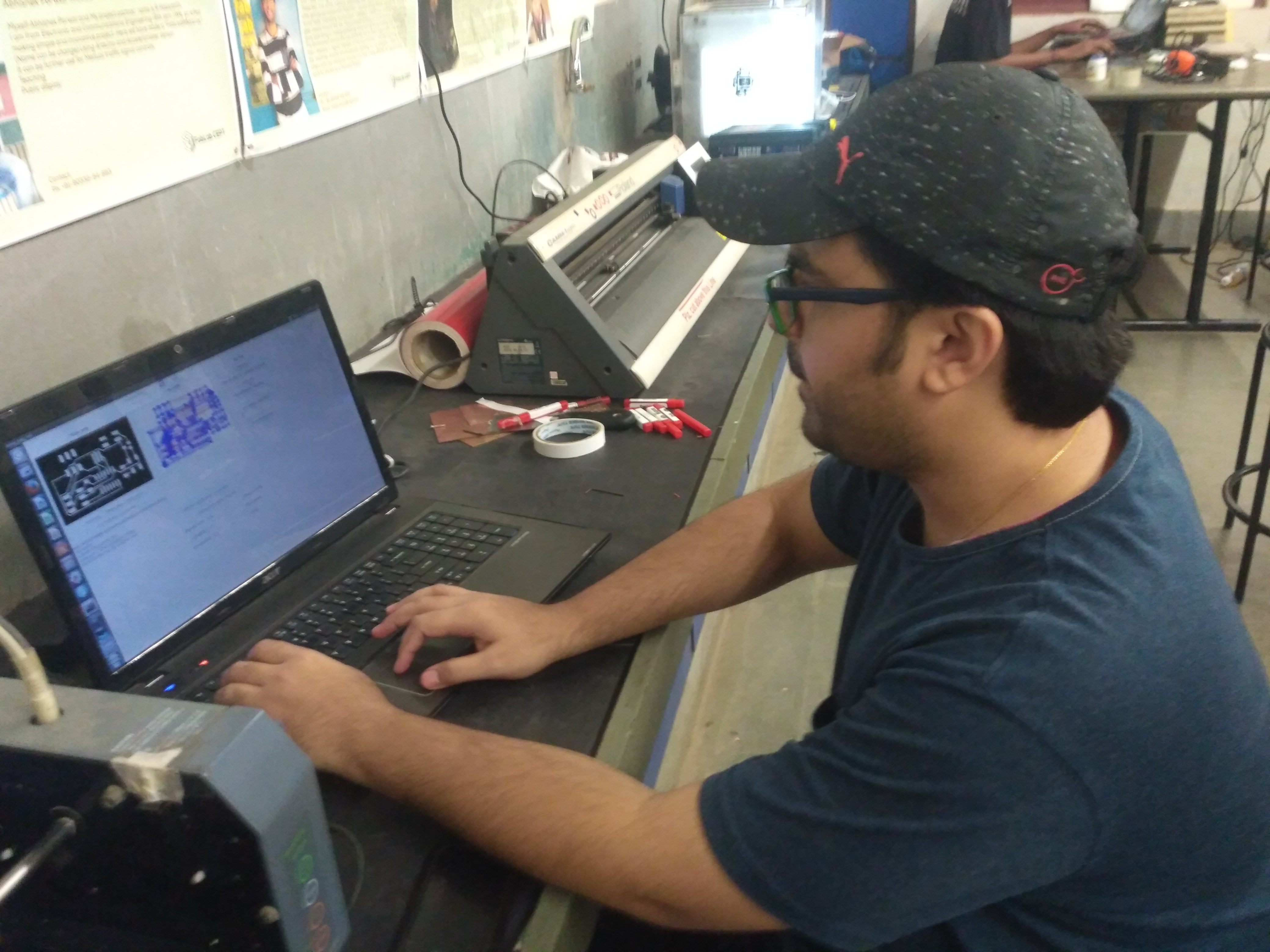
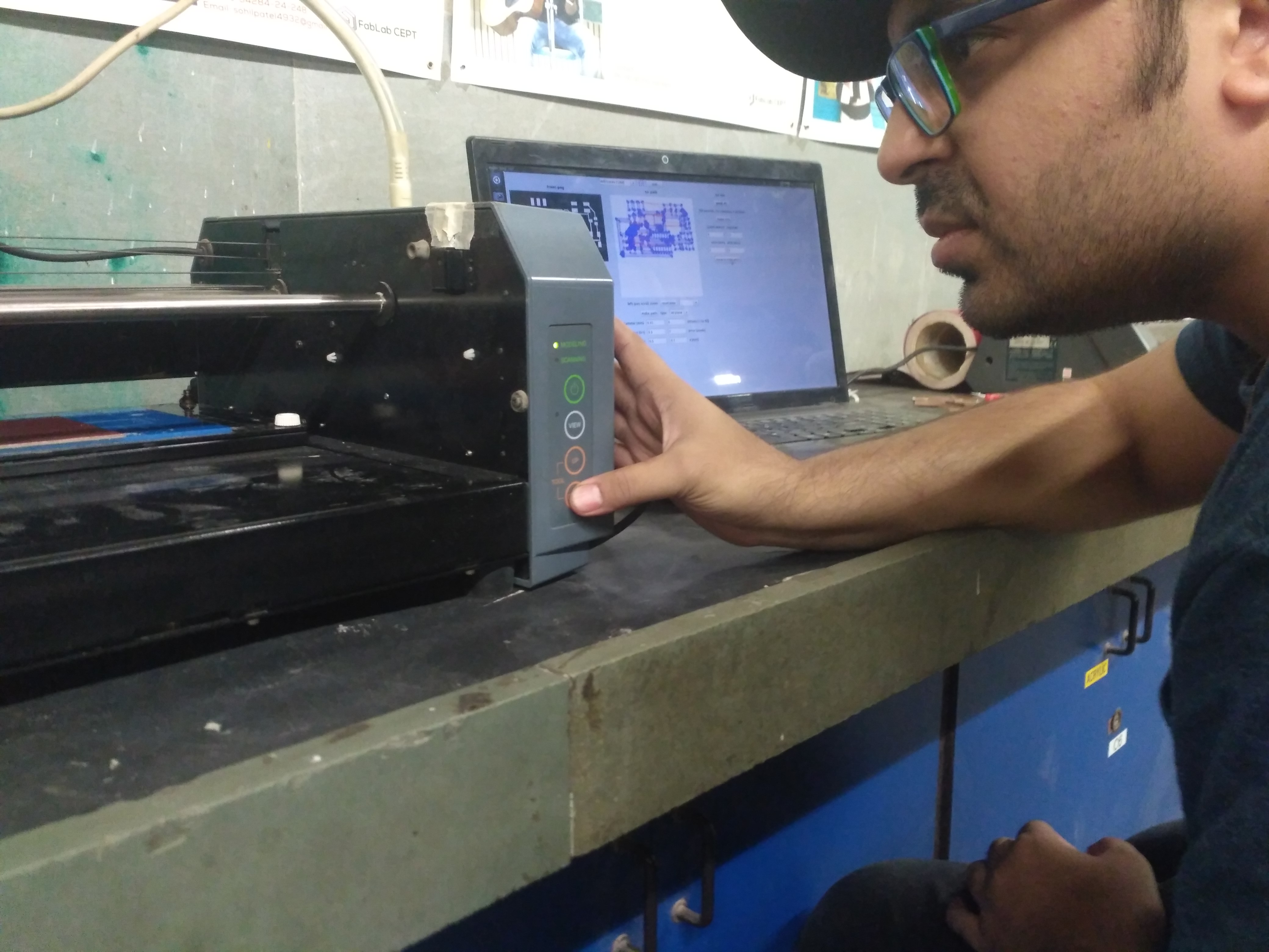
Me accessing the modela
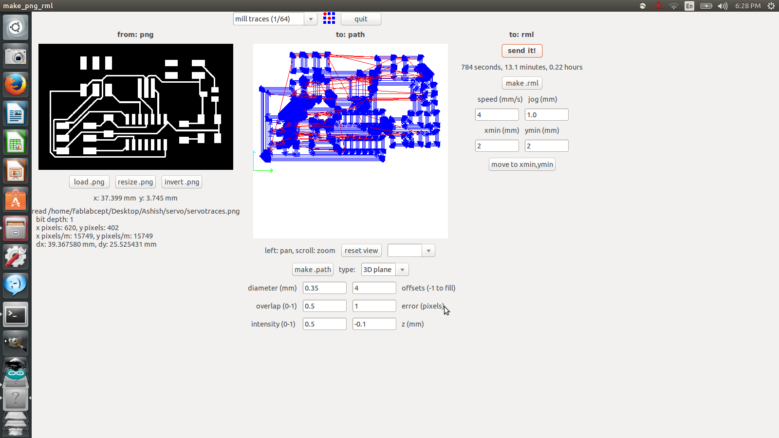
5. From the top scroll menu, I chose mill traces (1/64). After that, I chose the following settings:
- a. diameter (mm): 0.35
- b. overlap: 0.5
- c. intensity: 0.5
- d. offsets: 4
- e. error(px): 1
- f. z (mm): - 0.1
- xmin (mm) = 2 & ymin (mm) = 2
- speed (mm/s) = 4 & jog (mm) = 1.0
- Then I clicked on make .path and then make .rml which gave me an estimated time of completion.
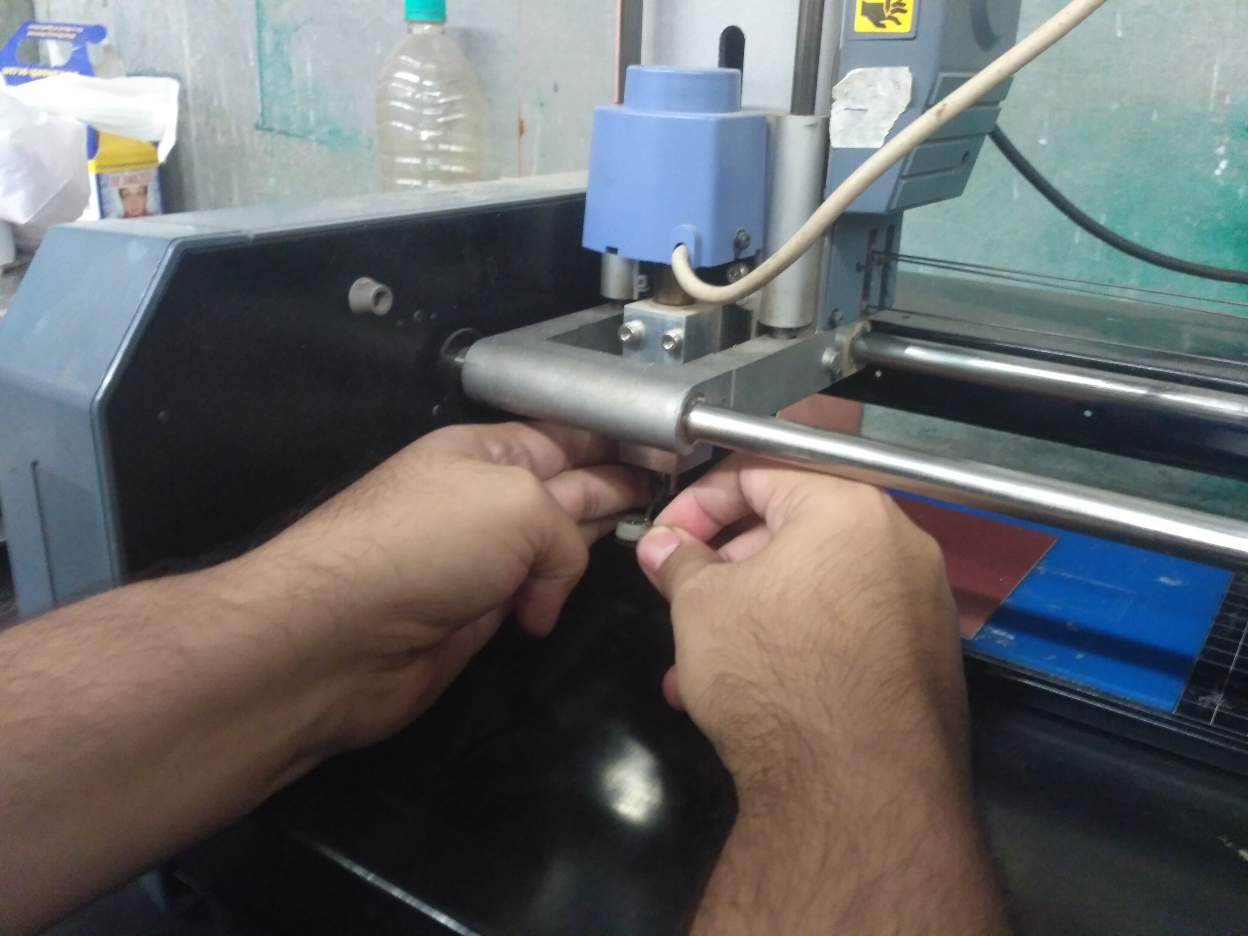
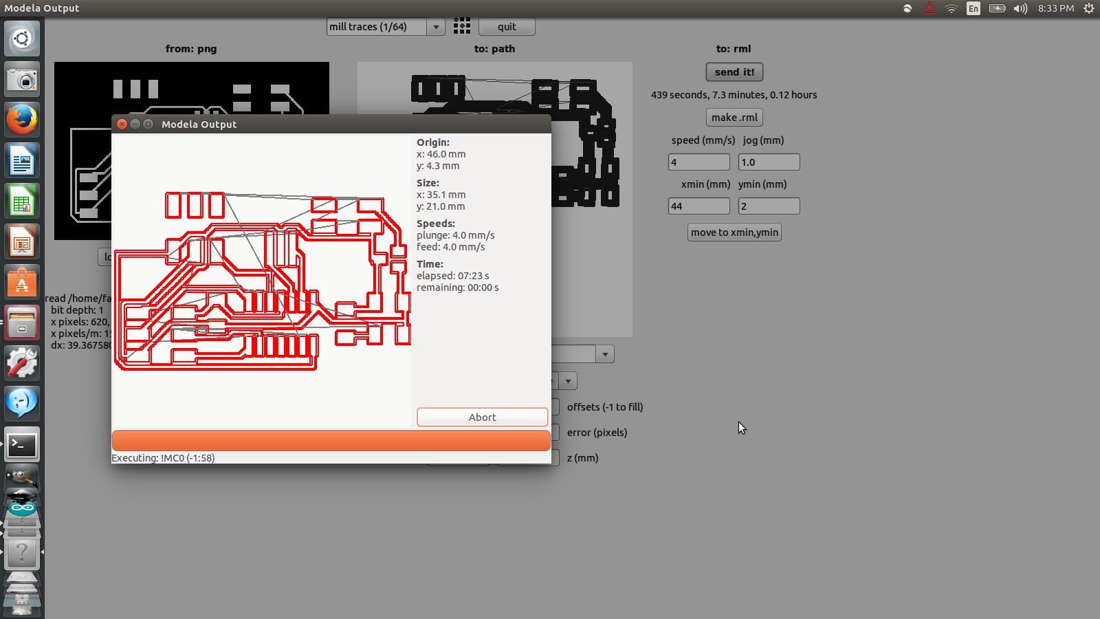
6. After that I clicked on send it and a new window popped up, showing the pathways to be taken by the machine. Then I clicked on Begin Milling.
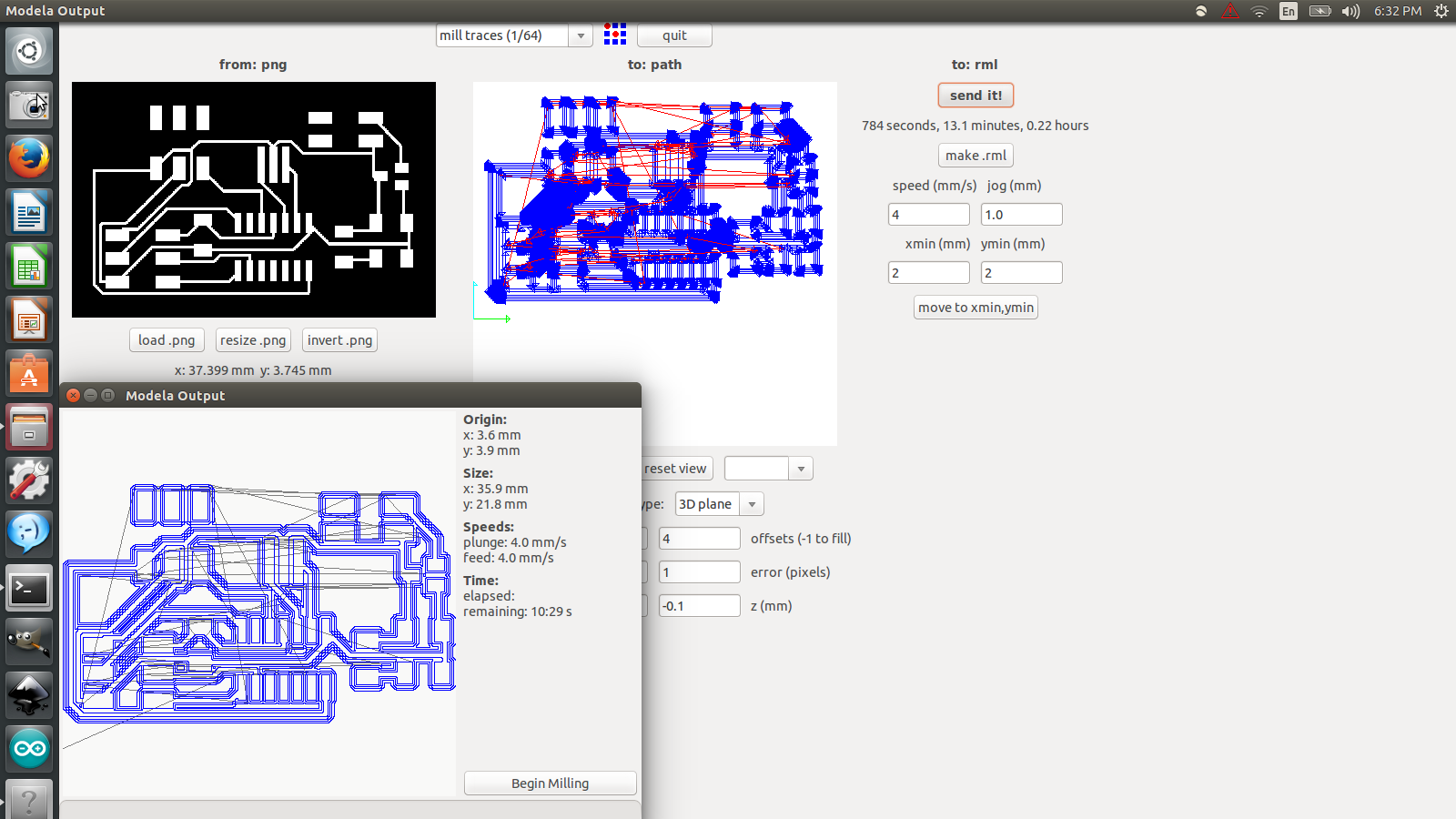
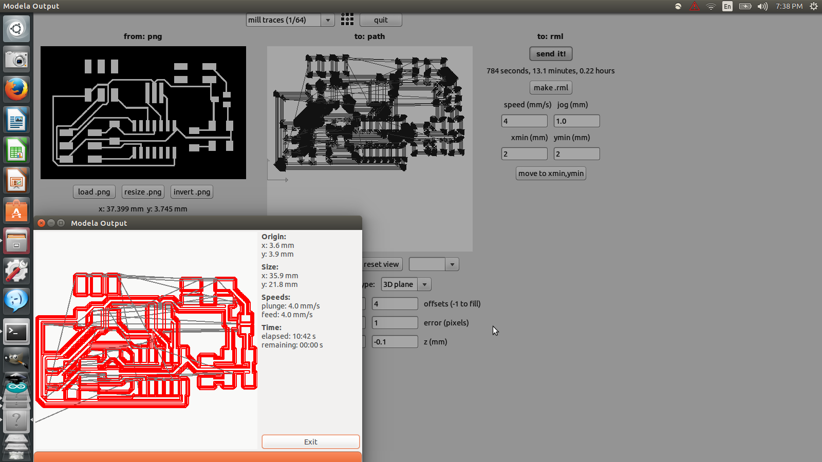
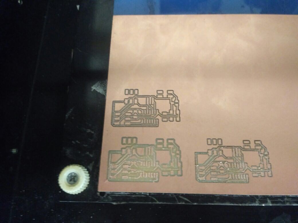
7. The window after the completion of the first print. Unfortunately, due to the settings, especially due to the high speed and high error value, the board didn’t turn out well.
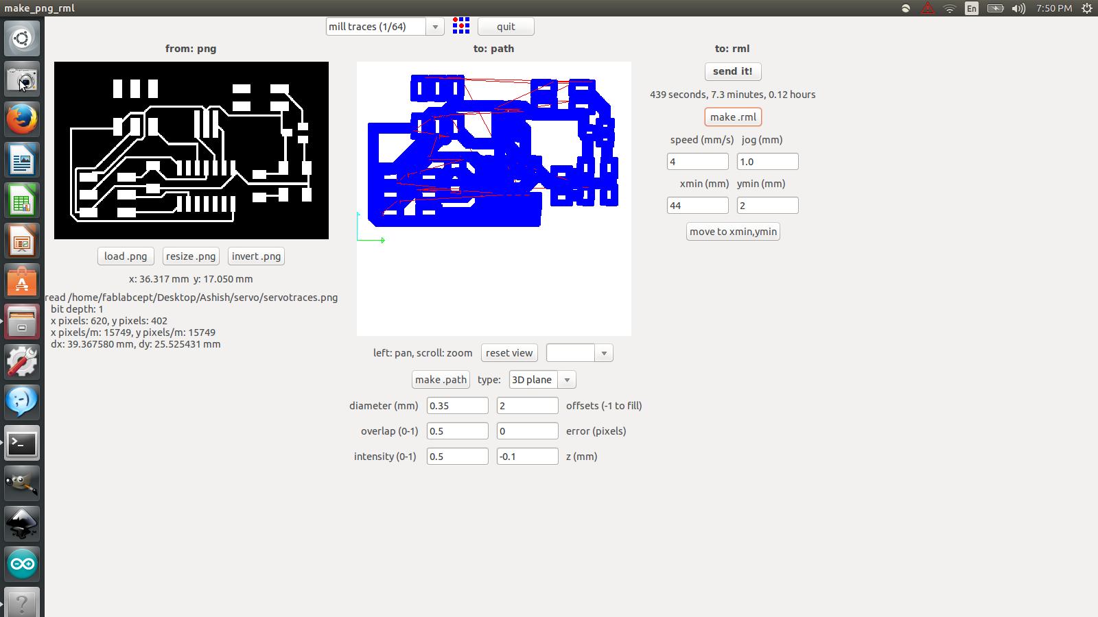
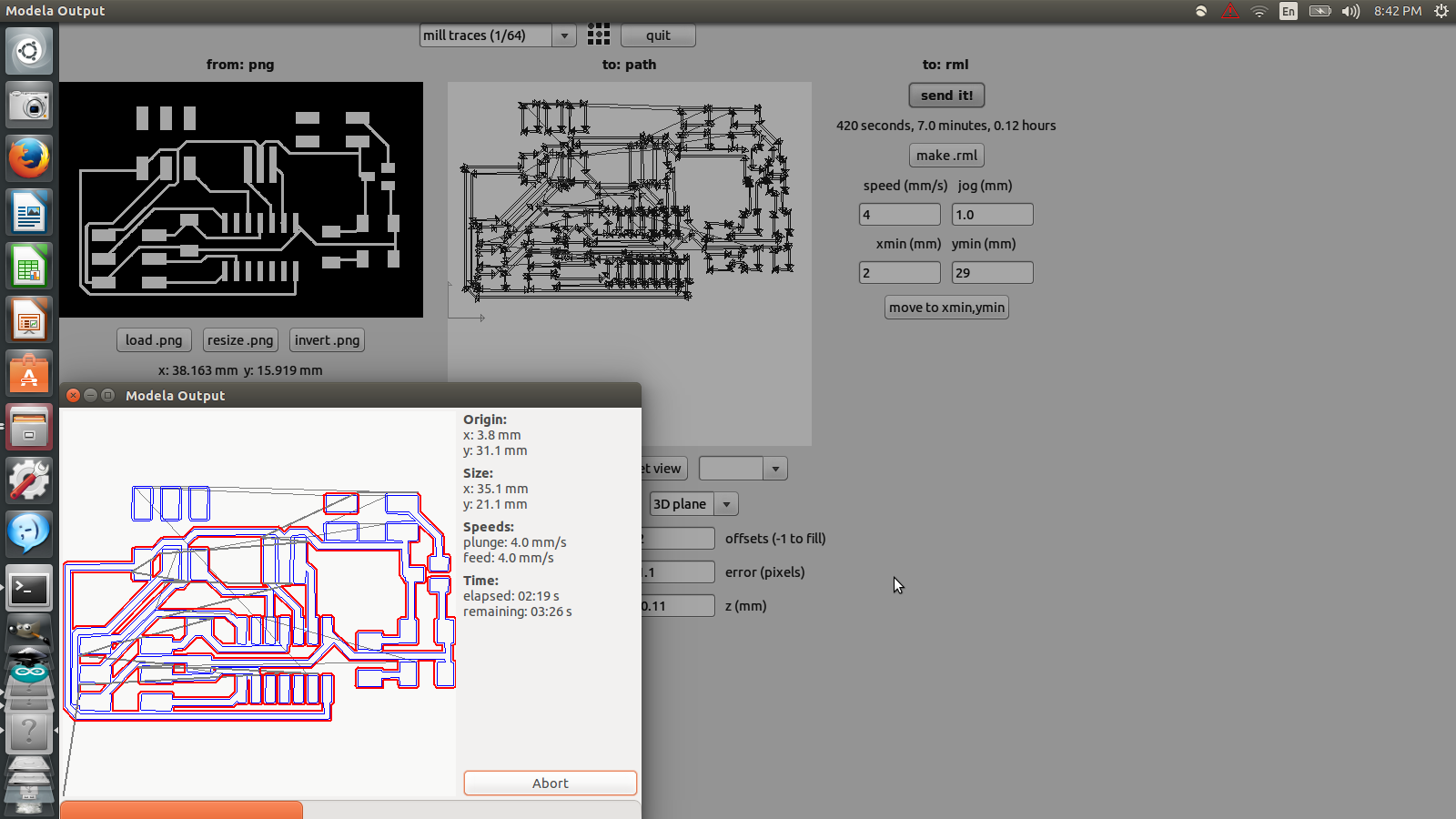
8. This was the next trial with new settings that are :
- diameter: 0.35
- overlap: 0.5
- intensity: 0.5
- offsets: 2
- error: 0
- z (mm): -0.1
- speed (mm/s): 4 & jog(mm): 1.0
- xmin (mm): 44 & ymin(mm): 2
9. Second trial also resulted in failure, disproving my assumption about the high speed and high error value being the culprit.
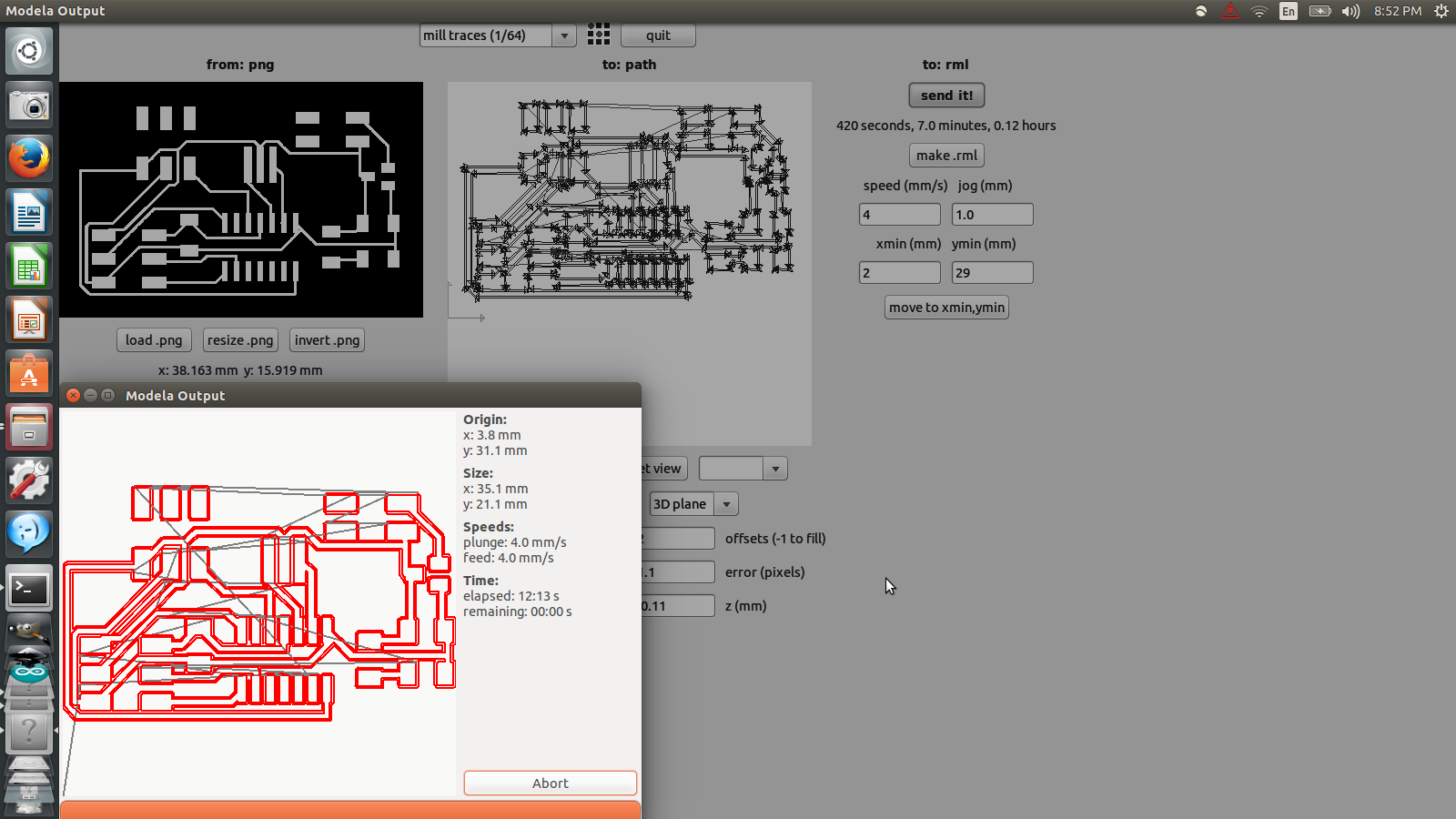
10. Third trial in progress. The settings are:
- Diameter (mm): 0.35
- overlap: 0.5
- intensity: 0.5
- offsets: 2
- error: 1.1
- z (mm): -0.11
- Speed (mm/s): 4 & jog (mm): 1
- Xmin (mm): 2 & ymin (mm): 29
11. Finally success was achieved. My analysis was corrected by Avishek Das who suggested that the cut depth being low was the source of the problem.
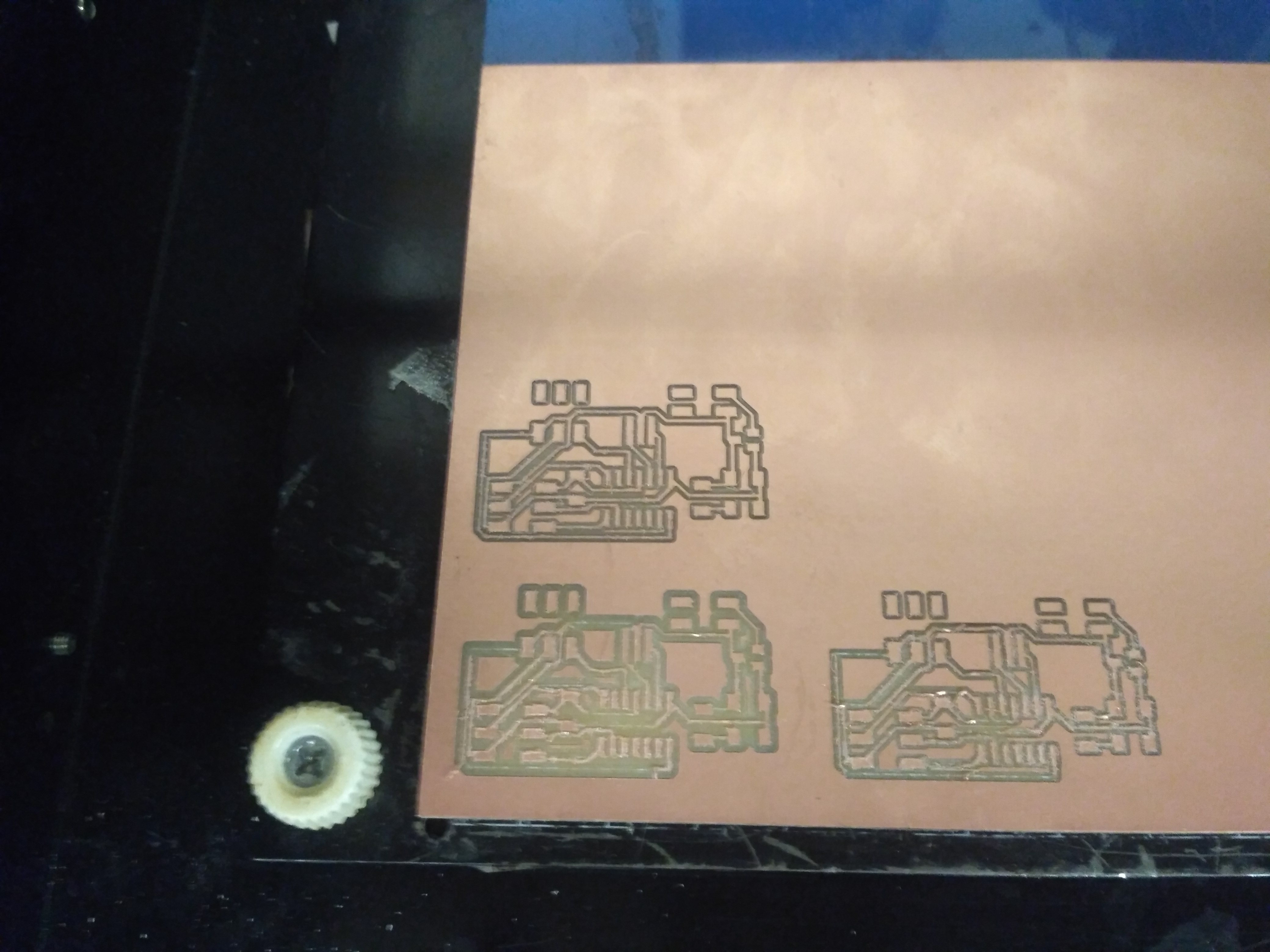
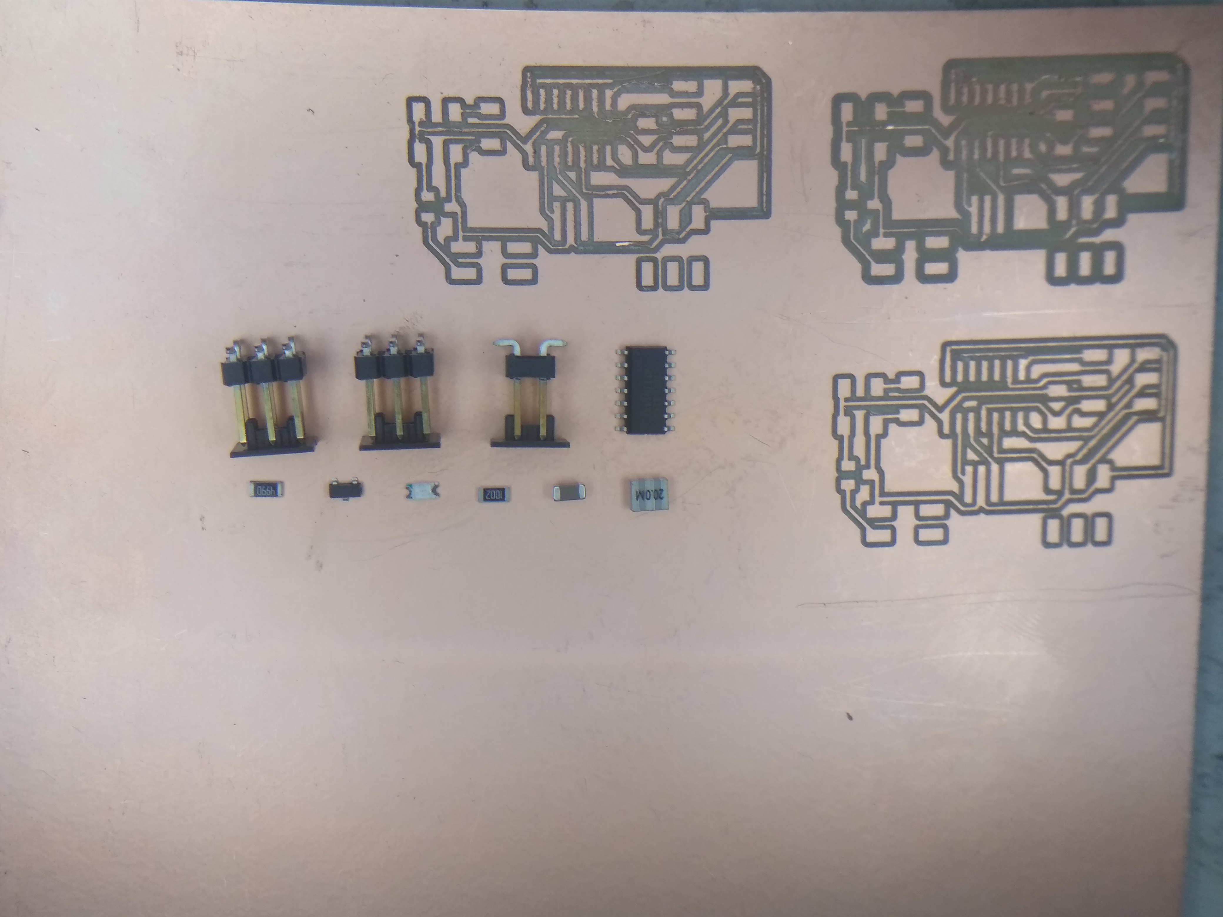
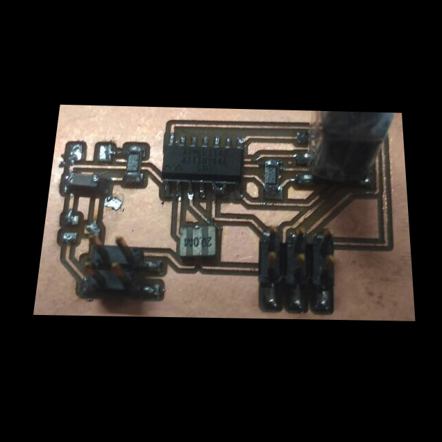
Now I could stuff the board with components and start coding.
Circuit Board
Code and Programming
For programming this board, I decided to build upon the official code given by Neil Gershenfeld. With the help of my friend Mohit Ahuja, I modified the code such that it runs only one servo motor via software PWM. That means that I controlled the servo using a manually generated series of high and low pulses. As explained in the beginning and elaborated in a Wikipedia page (link), the servo motor turns a set number of degrees for a set pulse width. Homofaciens on Youtube has an elaborate video on servos and how they work and how to even build one of your own. (embed video if possible). Here are the steps to upload the code to the ATtiny chip:
1. This program makes the board turn 0 degrees, 90 degrees and finally 180 degrees repeatedly. PB2 is attached to the signal pin of the servo.
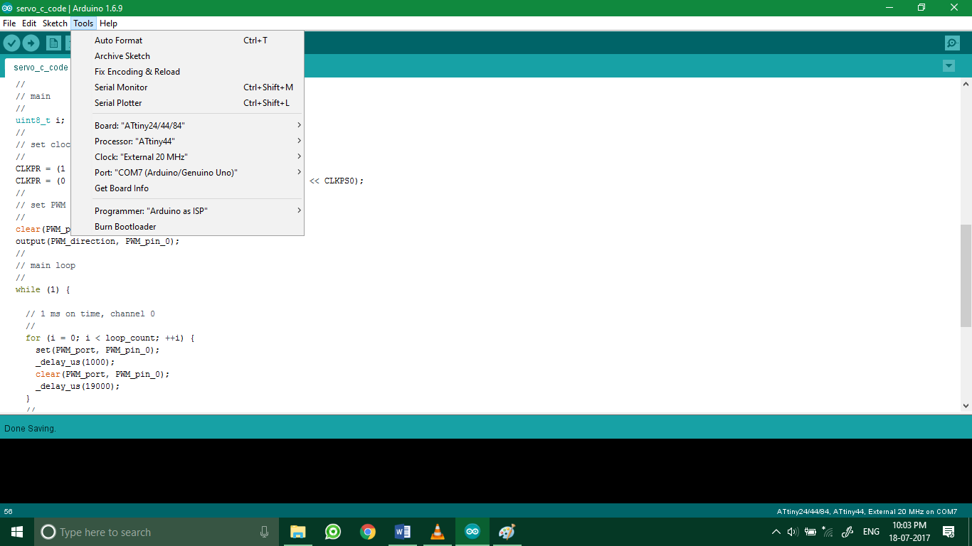
2. This screenshot shows the settings used to program the output board. Following are the settings listed out:
- Board: ATtiny 24/44/84
- Processor: ATtiny44
- Clock: External 20 MHz
- Port: COM7 (Different for different board and computer)
- Programmer: Arduino as ISP
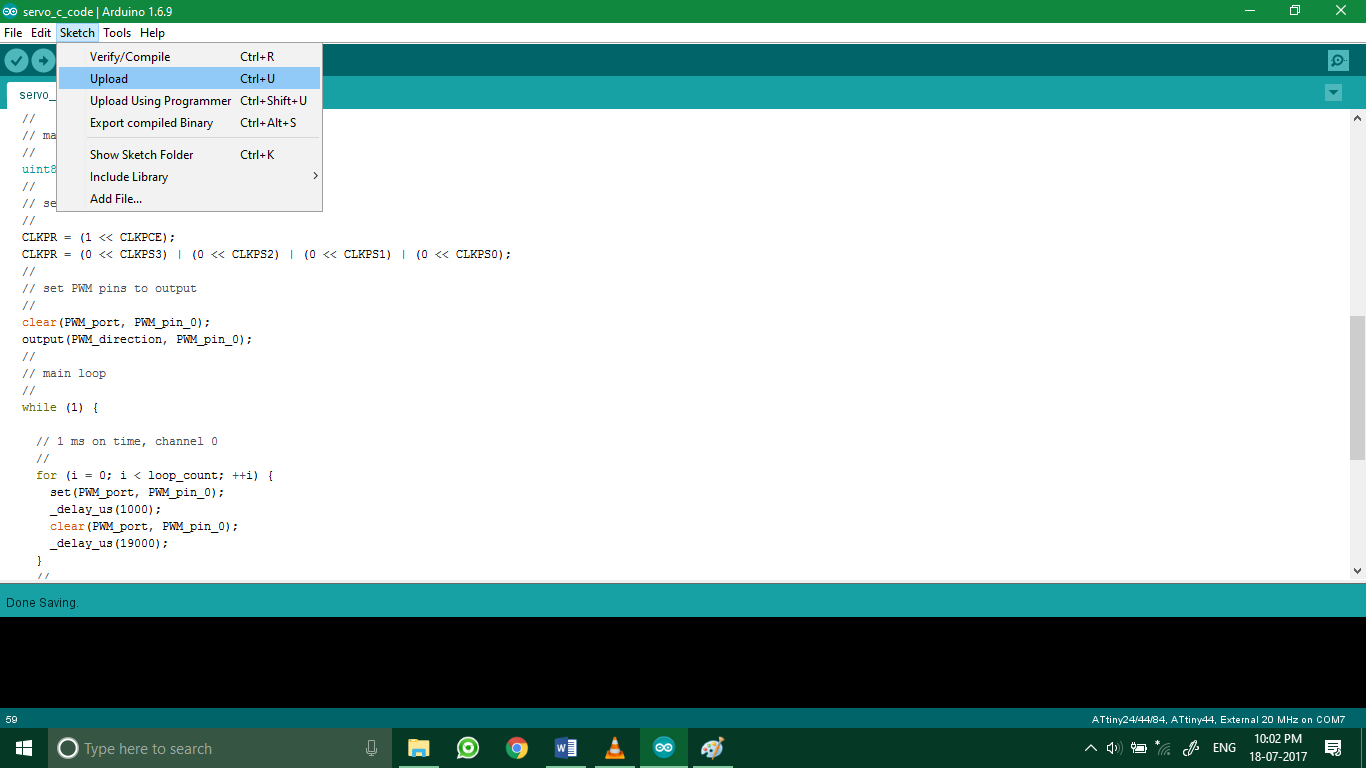
3. After burning the bootloader, I uploaded the code to the board by clicking Sketch > Upload.
Demo video
Below is a video demonstration of the working code.
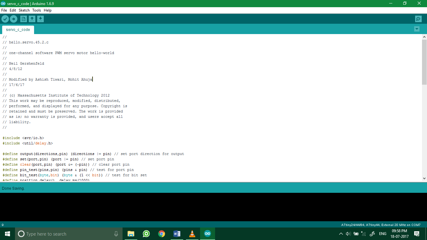
Code
//
// hello.servo.45.2.c
//
// one-channel software PWM servo motor hello-world
//
// Neil Gershenfeld
// 4/8/12
//
// Modified by Ashish Tiwari, Mohit Ahuja
// 17/6/17
//
// (c) Massachusetts Institute of Technology 2012
// This work may be reproduced, modified, distributed,
// performed, and displayed for any purpose. Copyright is
// retained and must be preserved. The work is provided
// as is; no warranty is provided, and users accept all
// liability.
//

#include
#include

#define output(directions,pin) (directions |= pin) // set port direction for output
#define set(port,pin) (port |= pin) // set port pin
#define clear(port,pin) (port &= (~pin)) // clear port pin
#define pin_test(pins,pin) (pins & pin) // test for port pin
#define bit_test(byte,bit) (byte & (1 << bit)) // test for bit set
#define position_delay() _delay_ms(1000)

#define PWM_port PORTB
#define PWM_direction DDRB
#define PWM_pin_0 (1 << PB2)

#define loop_count 30

int main(void) {
  //
  // main
  //
  uint8_t i;
  //
  // set clock divider to /1
  //
  CLKPR = (1 << CLKPCE);
  CLKPR = (0 << CLKPS3) | (0 << CLKPS2) | (0 << CLKPS1) | (0 << CLKPS0);
  //
  // set PWM pins to output
  //
  clear(PWM_port, PWM_pin_0);
  output(PWM_direction, PWM_pin_0);
  //
  // main loop
  //
  while (1) {

    // 1 ms on time, channel 0
    //
    for (i = 0; i < loop_count; ++i) {
      set(PWM_port, PWM_pin_0);
      _delay_us(1000);
      clear(PWM_port, PWM_pin_0);
      _delay_us(19000);
    }
    //
    // 1.5 ms on time, channel 0
    //
    for (i = 0; i < loop_count; ++i) {
      set(PWM_port, PWM_pin_0);
      _delay_us(1500);
      clear(PWM_port, PWM_pin_0);
      _delay_us(18500);
    }
    // 2 ms on time, channel 0
    //
    for (i = 0; i < loop_count; ++i) {
      set(PWM_port, PWM_pin_0);
      _delay_us(2000);
      clear(PWM_port, PWM_pin_0);
      _delay_us(18000);
    }
    //
  }
}
Links / Downloads / Code
Servo_driver Eagle schematicServo_driver Eagle board layout
C-code in '.ino'