Week 4
Electronics Production
Final Project
ASSIGNMENT
- Make an in-circuit programmer by milling the PCB
- Solder all the required components in the board.
- Optionally, trying other processes.
Getting Started With this week's assignment, We Following task to be done.
1) Milling The PCB.
2) Soldering
3) Programming The PCB to Work as a ISP Programmer.


MILLING PROCESS
FILES FOR MILLING
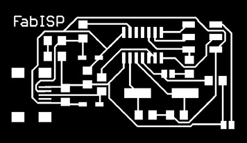
The FabISP Files to be used for Milling can be Found below
http://fab.cba.mit.edu/content/projects/fabisp/fabisp.png
We need black and white image in PNG Format.
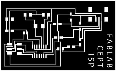
We at FabLab CEPT have our own version of FASISP designed Previously by
Its exactly same as FAB ISP just that, FABISP CEPT is little scaled up, to ease the learning curve with SMD soldering.
The Files for the same can be found hear
The procedure is well documented in FabLab CEPT's previous student Rudrapalsinh and Tapan, I took their REFERENCE.
GET FILE

The Board File to be Milled with 1/64 inch bit
Outline file for Through Cut I with 1/32 inch bit
MILLING THE BOARD
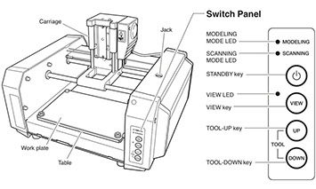
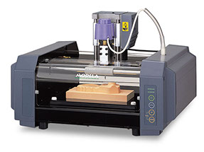
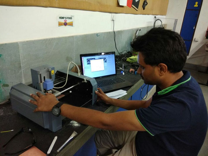
For Milling the PCB, We at FabLab CEPT have MODELA MDX 20 3D Milling Machine
To Control the Roland Milling Machine, We Use The older Version of FAB Modules installed in a laptop with Linux OS.
We use the Super User access to avoid any right and access issues later on.
To do so the Command is Simple
su
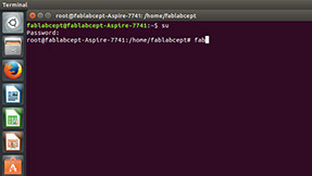
Terminal will ask for the password for the Super User of the Linux machine we are working on, enter the same and continue.
As the Fab Module is installed in the home directory of the default user in the Linux machine all we have to do is run the modules from the Terminal window with following command.
fab
Wola !! We have Fab Modules Interface Running.
Lets get started with setup for milling.
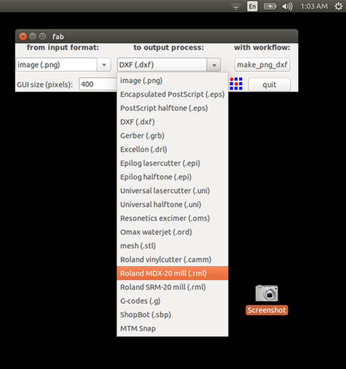
The First Option we select is the | Input Format | of the file we give our PCB design to the software.
In out case it PNG.
Next we Select Roland MDX-20 Mil(.rml) option as shown above. This is based on respective milling machine we have.
Now we click on >> make_png_rml button, This will open a new window.
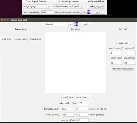
Next step was to import the image for trace tool-path. I used an image that was generated last year at FabLab Cept. Link for the same has be attached earlier above.
Next step was to import the image for trace tool-path. I used the PNG image of FABLAB CEPT ISP. Link for the same has be attached earlier above.
Note: only if the paths are not visible in white. Then We need to Inverse the image pressing invert.png
Once the window looks something like the first image below. (with black background), We are good to continue.
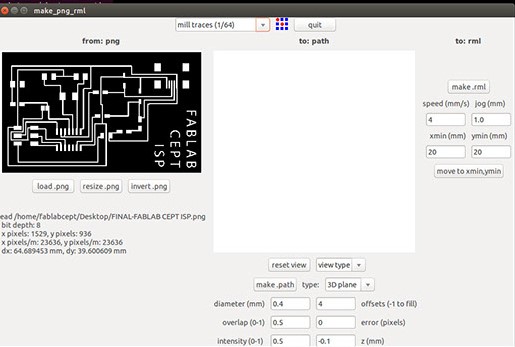
Next select The 1/64 inch bit. int the top drop-down
Next I adjusted the following settings:
- Type: 3D plane (this allows the the movement of axis in z direction)
- Diameter : 0.4mm (1/64inch) (here we specify the diameter of our milling bit, ideally should b 1/64in for milling and 1/32in for cutting)
- Offsets : 3mm (defines the offset of movement of the bit around white lines
- Overlap : 1
- Error : 0 pixels
- Intensity : 0.5
- Z(mm) : -0.1
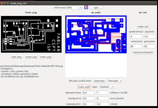
Next select click on make.path to generate the toolpath. above blue path will be visible
Now make.rml is pressed to make the GCODE compatible to Roland Milling machine
Once that is done we press on Sent it. Button this sends the GCODE to the machine.

Above image shows the path bit will follow to do the milling job.
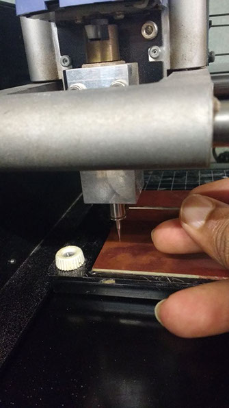
I stick the PCB Board using double sided tape.
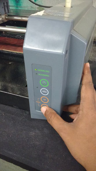
Now before we continue we set the origin.
Press view to see the current default origin of the head.
Now we move the head to X: 20 and Y: 20
(anywhere on the pcb is fine for this task)
Press the move to X Y Button and Your Drill bit should point the Respective point.
If thats working Machine is Successfully Receiving Our Commands.
- Now use the Hex key and open the screw on the dill bit.
- This will make the Drill bit fall on the PCB and tighten it again.
- And we are done with alignment of Z axis.
Note: TOP LEFT corner of the PNG will Allign to the ORIGIN we set.
Now press Send it! and Press Begin Milling.
- Note: Unlike Laser Cutting Machine, Modela Does Not has its own memory.
- What that Means is we need to make sure Laptop don't got to sleep mode
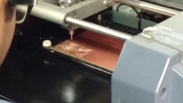
Me eagerly watching my first PCB been milled.
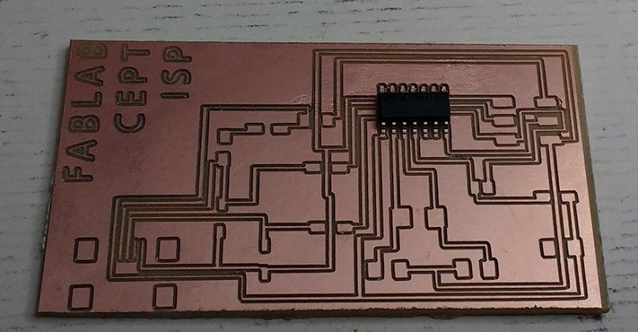
I forgot to click the picture after milling and right away started with soldering.
Below is the photos of the board in soldering stage.
SOLDERING PROCESS
I Refereed Below Tutorial to get started.
http://archive.fabacademy.org/archives/2017/doc/electronics_production_FabISP.html
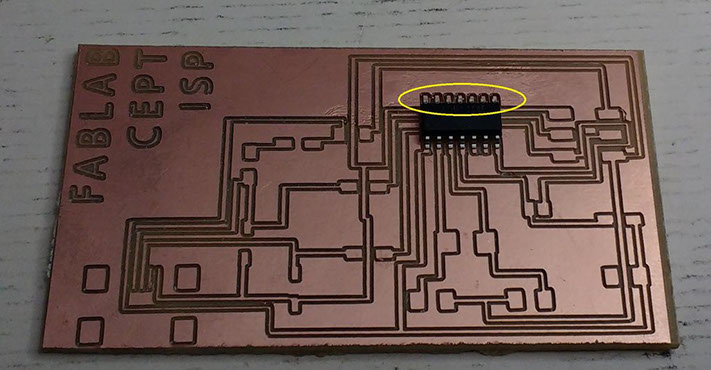
Due to Offset to 1 the above Yellow marked traces are very close.
The Task of soldering had to be very precise due to this.
COMPONENTS
The components for the FabISP are listed below
- Micro USB Header x1
- ATTiny 44 x1
- Zener Diode 3.3v x2
- Crystal 20 MHz x1
- 1 MicroFarad Capacitor x1
- 10 PicoFarad Capacitor x2
- 0 Ohm Resistor x2
- 100 Ohm Resistor x2
- 1000 Ohm Resistor X1
- 10000 Ohm Resistor x1
- 499 Ohm Resistor x1
- 6 Pin Header x1
Solder The components in Following order:
- USB header: This was the most tricky part so start with this one first.
- Attiny 44 : While soldering the micro-controller we need to take care of not burning it.
- Notice the dot on the microcontroller it has to be pointing towards USB header.
- Zener Diodes: They have a direction of orientation which has to be considered.
- Crystal
- Capacitor
- Resistors
- 6 Pin Header
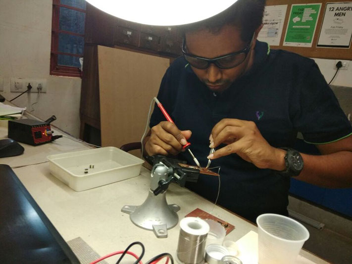
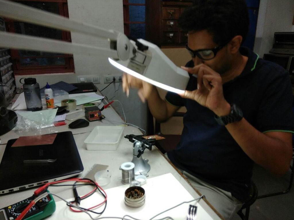
SAFTEY:
While soldering safety goggles are must !!
TESTING THE CIRCUIT
To Test if the PCB is working do the following
Power the FAB ISB with usb cable
Connect the AVR programmer to FAB ISB via flat 6 pin cable
Power the AVR with USB too.
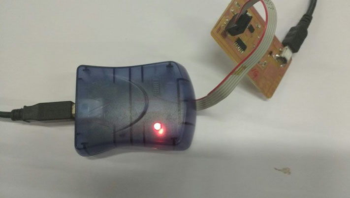
Now if get Orange Light Blinking We Flip the Directon of 6-pin Header.
If it is Red Light even after flipping the Direction of 6-Pin Header we could have problem with soldering of Circuit.
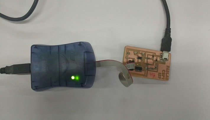
If it is Display Green Light. Our PCB is Working and has no Power Supply Issues.
If it is Display Green Light. Our PCB is Working and has no Power Supply Issues.
That shows all connections are correct
PROGRAMING THE FABISP
For this task, I referred to this link.
http://archive.fabacademy.org/archives/2016/doc/programming_FabISP.html
This week we had Ohad Mehuyas (instructor) to guide us with programming the FabISP.
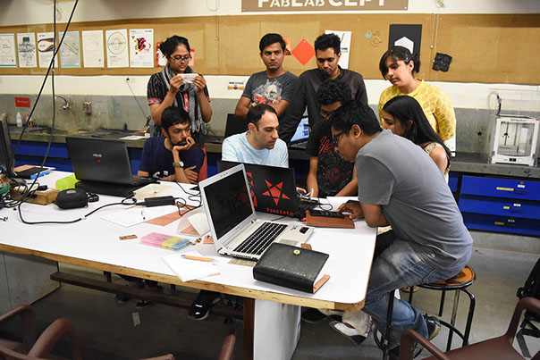
I connected the board to the AVR and to the linux pc to program the FabISP. Next I followed the steps mentioned in the link above to program the FabISP.
- make clean
- make hex
- make fuse
- make program
I used a computer with Ubuntu for programming. The first step is to open the terminal and type:
sudo apt-get install flex byacc bison gcc libusb-dev avrdude
Next type :
sudo apt-get install gcc-avr
Next it asked for confirmation, so I typed "y" , meaning 'yes'.
Next type :
sudo apt-get install avr-libc
sudo apt-get install libc6-dev
Download the Firmware
Move to the desktop with following command
cd ~/Desktop
Download the firmware from the Fab Academy Electronics Production page.
wget http://academy.cba.mit.edu/classes/embedded_programming/firmware.zip
Unzip the firmware
unzip firmware.zip
The next step was to connect the FabISP to computer to power it up.
The 6-pin header on FabISP is connected to AVRISP
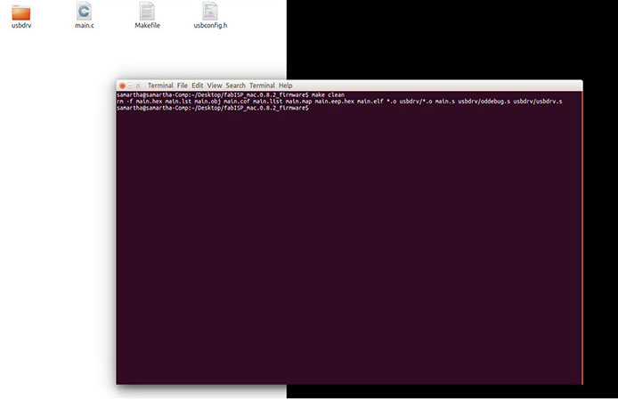
I went in to the firmware folder and accessed Terminal from that location. and typed
make clean
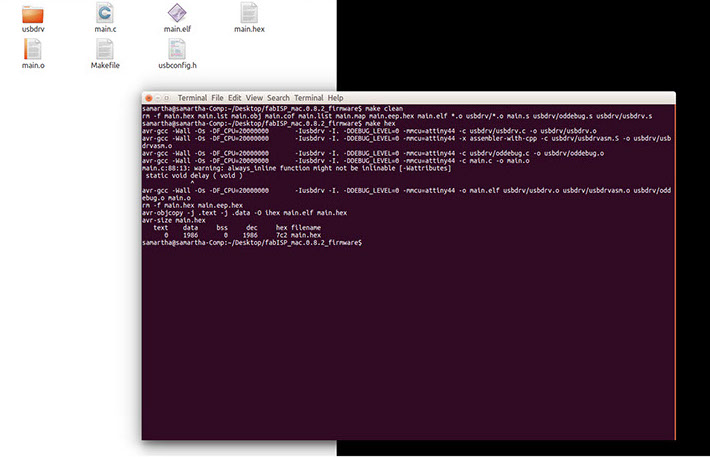
Next I wrote : Make Hex
It created the necessary file highlighted above.
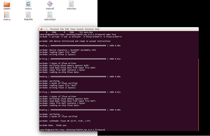
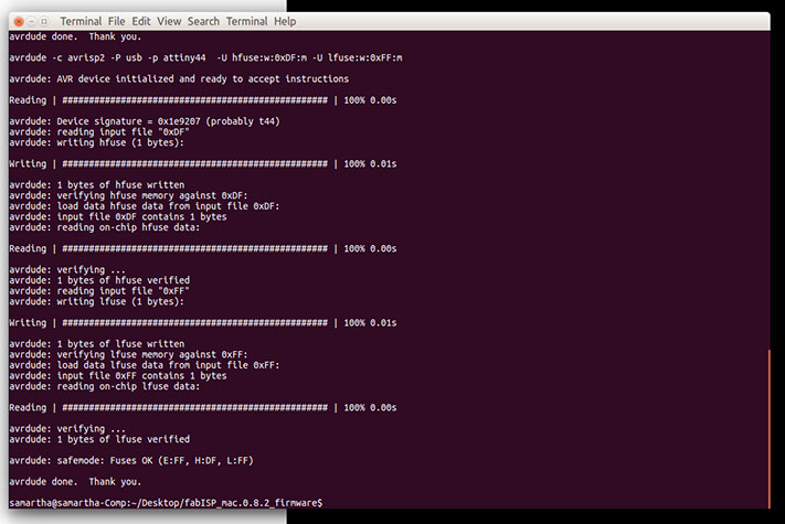
Next Command is: make fuse
This command ran successfully and the last message I got was "avrdude done. Thank you"
At last I typed : make program
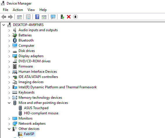
To Test if it getting detected connected it with windows Device is Detected as FabISP
LEARNINGS OF THE ASSIGNMENT
- Learned how to solder the SMD components for the first time.
- Understood the Functioning of ISP
- Got a hands on PCB Milling with Modela Machine.