Week 10
OUTPUT DEVICES
Final Project
ASSIGNMENT
- Describe the design and fabrication process.
- Programming process.
- Outlining the problem and their fix.
- Design files and Code.
This week assignment was to design a board for output device program it to show some output.
I have Designed a Servo Board as I need one for my final project


UNDERSTANDING DATASHEET
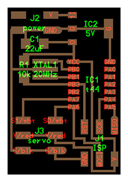
I Started Referring To Niel's board as below and decided to use ATtiny45 For the same.
Reference: http://academy.cba.mit.edu/classes/output_devices/index.html
ATtiny 4
Data-sheet LINK

Above is the PINMAP of attiny44/48
Following are the important Information That will help us move to next step.
- Default Frequency: 1MHZ
- Attiny44 Run at default speed of 1Mhz using it internal Clock
- We can make it Run at 8MHz as well but it wont be so accurate.
- To Make it Run AT 20Mhz we need a External Cristal or Resonator attached to Attiny44.
- Below Diagram shows how External Cristal will be connected apart form other IO PINS
SERVO
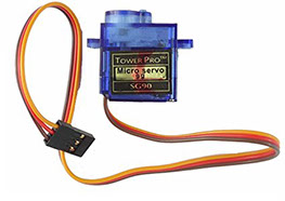
ABOUT THE SERVO WE ARE TRYING TO CONTROL
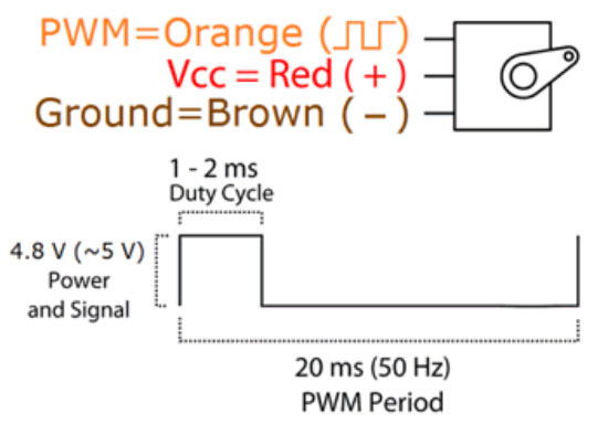
Position "0" (1.5 ms pulse) is middle, "90" (~2ms pulse) is middle,
is all the way to the right, "-90" (~1ms pulse) is all the way to the left.
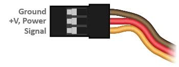
- We Also need to keep in mind the above header sequence which is Standard for most servos.
- The VCC pin in in center
- The Ground on one side and Signal on other. This is where we give the PWM Signal which will control the servo.
DESIGNING THE PCB V1
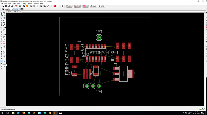
The Above Board is the one I Designed First While Referring at neel's Board attached at top of page.
It had Following Component
- Resonator 20MHZ
- 5v Voltage Regulator.
- 1uf Capacitor
- 10K resistor
- 22uf Capacitor
- Attiny44
- and the pin headers
I found out that the board will work fine without external resonator
So I decided to go away with it and try without it.
Wanted to reduce the number of components.
So below is the board without it. it also reduces the
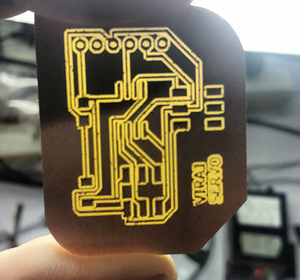
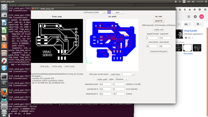
I went ahead and Did Auto routing for the same and created the paths as below
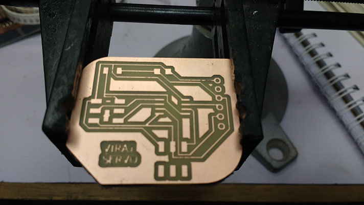
And milled The same with below settings

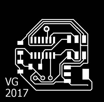
photo of milled PCB
Now When I Checked the PCB by powering it up and I found the following issue
- The 5V Linear Voltage regulator was getting a Input voltage of 5V and it was not giving 5V As output which is obvious.
- The output voltage was around 3 to 4 v which is less for servo,
- The whole idea of using the Linear Voltage Converter was to give more Current to The Servo
- Earlier plan was to drive two servos as done by Neel in above reference
- Also the voltage regulator which we have in lab is different from what Neel has used
- I decided to got ahead without voltage regulator for my Next Version.
- However is one can find the right voltage regulator bellow are my files for working on the same.
FILES ATTACHED
Attached is the Board (.brd) File from eagle
GET FILE
Attached is the Schematic File ( .sch) from eagle
GET FILE
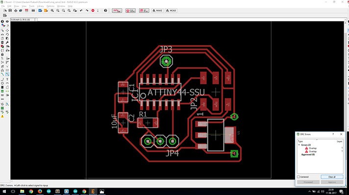
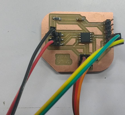
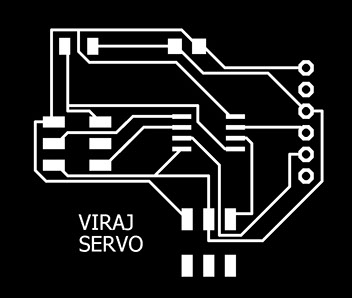
DESIGNING THE PCB - V2
I Designed a Second version of it with Attiny45 and Without 5v Voltage Regulator and 20 Mhz Crystal.
Below is the New Design for the Same

Also note the above green highlighted area.
I have used 6 Pin header as the 3 pin headed was not as stable over the board when servo is connected and disconnected frequently.
Thanks to my friend Mohit Ahuja for Guiding while designing this.
This new Design had following Components
- Attiny45
- 10K Resistor
- 1uf Capacitor
- 6 Pin Header (eagle component name is AvrispSMD)
- and Jumper headers for FTDI pin
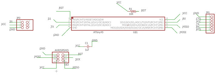
The Pins are attached as Follows
- PB3 to Servo pin S1
- PB2 to FTDI Rx
- PB4 to FTDI Tx
- all AVISP pins as standard
- Capacitor 1uf over Ground and VCC
- and Resistor over RST of AVRISP and VCC
Went Ahead and Milled the same on Roland Modela
with offsets 1 and Error 0
- Note The Traces Been too Close because of less isolations
- this would resulted into shorting of ATtiny 45 legs
I Did mill a Second PCB
- With Offset to 4 for more isolation
- and Error as 0
I also Placed the Components little away from each other and did small change in routing as seen in above comparative gif.
This Time It came out Really Well Isolated.
Finally Verison 2 with Attiny45 is ready to solder
FILES ATTACHED
Attached is the Board (.brd) File from eagle
GET FILE
Attached is the Schematic File ( .sch) from eagle
GET FILE

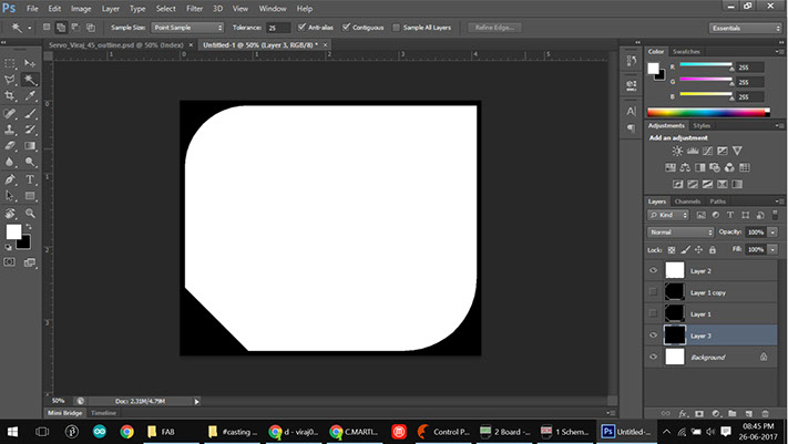
The Above Image Was edited in Photoshop. This is done to create a path outside the broad area we need a isolation that is black read to be cut out.
Video of Milling the Same.
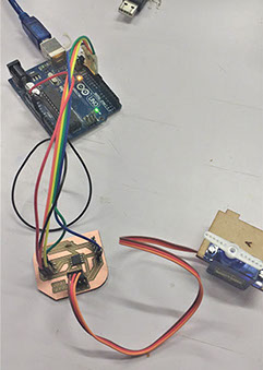
PROGRAMMING THE BOARD
For programming the board, I prepared my Arduino UNO to work as ISP.
Next, I connected my board with arduino using the MISO,MOSI, SCK, RST, GND and VCC pins.

Above are the pins on arduino which will be connected to Respective pin on The Input Device
Next I used the Below Code and uploaded the same.
For Testing if the Servo Sweeps
Pin 3 is our Servo Pin. Its is a PWM pin.
#include <SoftwareSerial.h>
// ***
// *** Define the RX and TX pins. Choose any two
// *** pins that are unused. Try to avoid D0 (pin 5)
// *** and D2 (pin 7) if you plan to use I2C.
// ***
#define RX 4 // *** D3, Pin 2
#define TX 2 // *** D4, Pin 3
// These constants won't change. They're used to give names
// ***
// *** Define the software based serial port. Using the
// *** name Serial so that code can be used on other
// *** platforms that support hardware based serial. On
// *** chips that support the hardware serial, just
// *** comment this line.
// ***
SoftwareSerial Serial(RX, TX);
void setup() {
// initialize serial communications at 9600 bps:
Serial.begin(9600);
pinMode(3, OUTPUT);
}
void loop()
{
for (int i = 0; i < 50; ++i) {
digitalWrite(3, HIGH);
delayMicroseconds(2000); //
digitalWrite(3, LOW);
delayMicroseconds(18000);
}
delay(2000);
for (int i = 0; i < 50; ++i) {
digitalWrite(3, HIGH);
delayMicroseconds(1500);
digitalWrite(3, LOW);
delayMicroseconds(18500);
}
Serial.println("1"); // Just for Debugging not other purpose
}
The same code is been attached below
GET FILE
How PWM Angle Control for Servo Works ?
Writes a value in microseconds (uS) to the servo, controlling the shaft accordingly. On a standard servo, this will set the angle of the shaft. On standard servos a parameter value of 1000 is fully counter-clockwise, 2000 is fully clockwise, and 1500 is in the middle.
For Angle of 0 we give a pulse of 1000 and the second pulse of 20000- 1000 = 19000
Same for 1500 that is midway at 90 angle we give first pulse hight for 1500miliconds and second pulse high for 20000-15000 = 18500 Milliseconds
LEARNINGS OF THE ASSIGNMENT
- Understood PWM signal and how to program the same.
- Understoop Working With power managment and Voltage Regulator