Week 16: Interface and Application Programming
Tasks for the week:
- Write an application that interfaces with an input and/or output device that you made, comparing as many tool options as possible.
I added button and LED on my echo hello board during electronics design week with the scope of using it as an input device that shows data by blinking LED. Hence, I decided to develop an interface for my hello echo board this week.
Task:01 Developing Interface
I chose to use processing this week to develop a GUI as it is similar to Arduino IDE. I found it easier to use, hence went ahead with it.
Processing can be downloaded from this link.
"Processing is an open source computer programming language and integrated development environment (IDE) built for the electronic arts, new media art, and visual design communities with the purpose of teaching the fundamentals of computer programming in a visual context, and to serve as the foundation for electronic sketchbooks."-wikipedia
I started by looking at a few tutorials to develop an interface in processing. I simultaneously repeated the steps as in the tutorial to develop and understand the process of developing the interface. The screenshots below explain my process.
.jpg?crc=137923633)
The above window opens on opening a new Processing file.
.jpg?crc=4036301323)
.jpg?crc=64186633)
Next, since I was following a tutorial, I downloaded the library for ControlP5 from Tools>Libraries.
.jpg?crc=3899162172)
Next, I declared GUI library -Control P5 and set the size of the GUI as 600600 pixels.
.jpg?crc=3925978366)
Further, I initialized the GUI library.
I tried running the code, but since, I had only given a size and 0 value for background it showed me black box of 600x600 pixels.
.jpg?crc=441243628)
I was trying to add a slider, hence I added command "Slider s= jControl.addSlider("back_color",0,255,10,100,10)". Here, 0, 255 are the black and white colour that would appear while using the slider, 10 is the step, next 10 is the height and 100 is the length of the slider.
.jpg?crc=4294524092)
I tried 500 value instead to 255 to change colour and run the code. As seen in the image above it worked perfectly as in the tutorial video.
The processing file can be found here.
The tutorial I referred can be seen below:
Task:02 Developing Interface for the Hello Echo Board
Since I used Attiny 44 for my echo hello board, I needed to add software serial to get data via serial communication. I needed to send data from my GUI to make LED on my board blink.
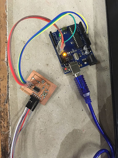
Hence, to begin with I modified the basic blink code of arduino and added Software serial to the code to begin serial communication between the RX-TX pins. The image below shows the MISO, MOSI, SCK connections from my board to the arduino via which I uploaded the code onto my board. The codes can be seen besides the image.
#include<SoftwareSerial.h>
int rxPin = 1;
int txPin = 0;
char val; // Data received from the serial port
int ledPin = 7; // Set the pin to digital I/O 4
SoftwareSerial myserial(rxPin, txPin);
void setup() {
pinMode(ledPin, OUTPUT); // Set pin as OUTPUT
myserial.begin(9600); // Start serial communication at 9600 bps
}
void loop() {
while (myserial.available()) { // If data is available to read,
val = myserial.read(); // read it and store it in val
}
if (val == 'H') { // If H was received
digitalWrite(ledPin, LOW); // turn the LED on
} else {
digitalWrite(ledPin, HIGH); // Otherwise turn it OFF
}
delay(100); // Wait 100 milliseconds for next reading
}
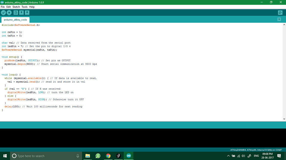
The above image shows the codes that I used to build the serial communication on my board.
Next, I used the basic simplewrite sketch of processing and modified it to develop my own customised GUI. The modified codes can be viewed below:
/**
* Simple Write.
*
* Check if the mouse is over a rectangle and writes the status to the serial port.
* This example works with the Wiring / Arduino program that follows below.
* modified by Chandni Chhabra
*/
import processing.serial.*;
Serial myPort; // Create object from Serial class
int val; // Data received from the serial port
void setup()
{
size(200, 200);
// I know that the first port in the serial list on my mac
// is always my FTDI adaptor, so I open Serial.list()[0].
// On Windows machines, this generally opens COM1.
// Open whatever port is the one you're using.
String portName = Serial.list()[1];
myPort = new Serial(this, portName, 9600);
}
void draw() {
background(255);
if (mouseOverRect() == true) { // If mouse is over square,
fill(204); // change color and
myPort.write('LED ON'); // send an H to indicate mouse is over square
}
else { // If mouse is not over square,
fill(0); // change color and
myPort.write('LED OFF'); // send an L otherwise
}
rect(50, 50, 100, 100); // Draw a square
}
boolean mouseOverRect() { // Test if mouse is over square
return ((mouseX >= 50) && (mouseX <= 150) && (mouseY >= 50) && (mouseY <= 150));
}
I modified the code such that, when I hover the cursor over the GUI, it sends a 'LED high' signal on my board leading to lighting up my LED.
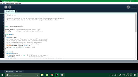
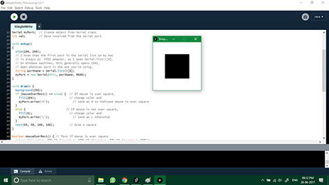
The above images show the simple write code that I used to develop my interface in Processing.
The below video and images shows the working of the code on my echo hello board.

EX-TERRA-DUR by Chandni Chhabra is licensed under a Creative Commons Attribution-ShareAlike 4.0 International License.