week 6
Electronics Design
ASSIGNMENTS:
- Describe the process of making 'echo hello-world' board with additional LED, buttons & current limiting resistor.
- Explaining the possible problems and their solution.
- Inclusion of original design files.
weekly work
understanding
attiny 44
final project
My knowledge in the electronics is very elementary and I don't know how MCUs function. I have worked with Arduino like commercially available boards before but their internal function was not known to me.
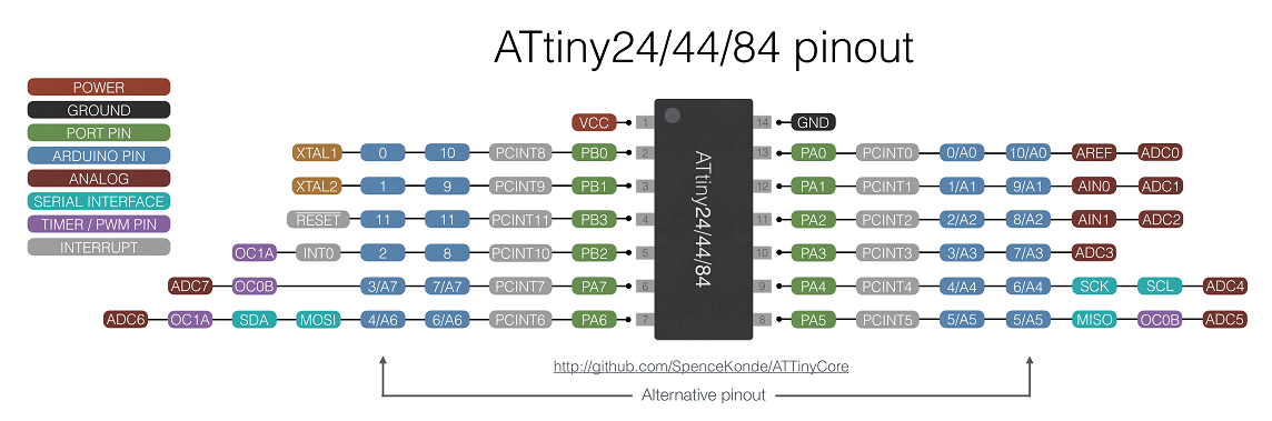
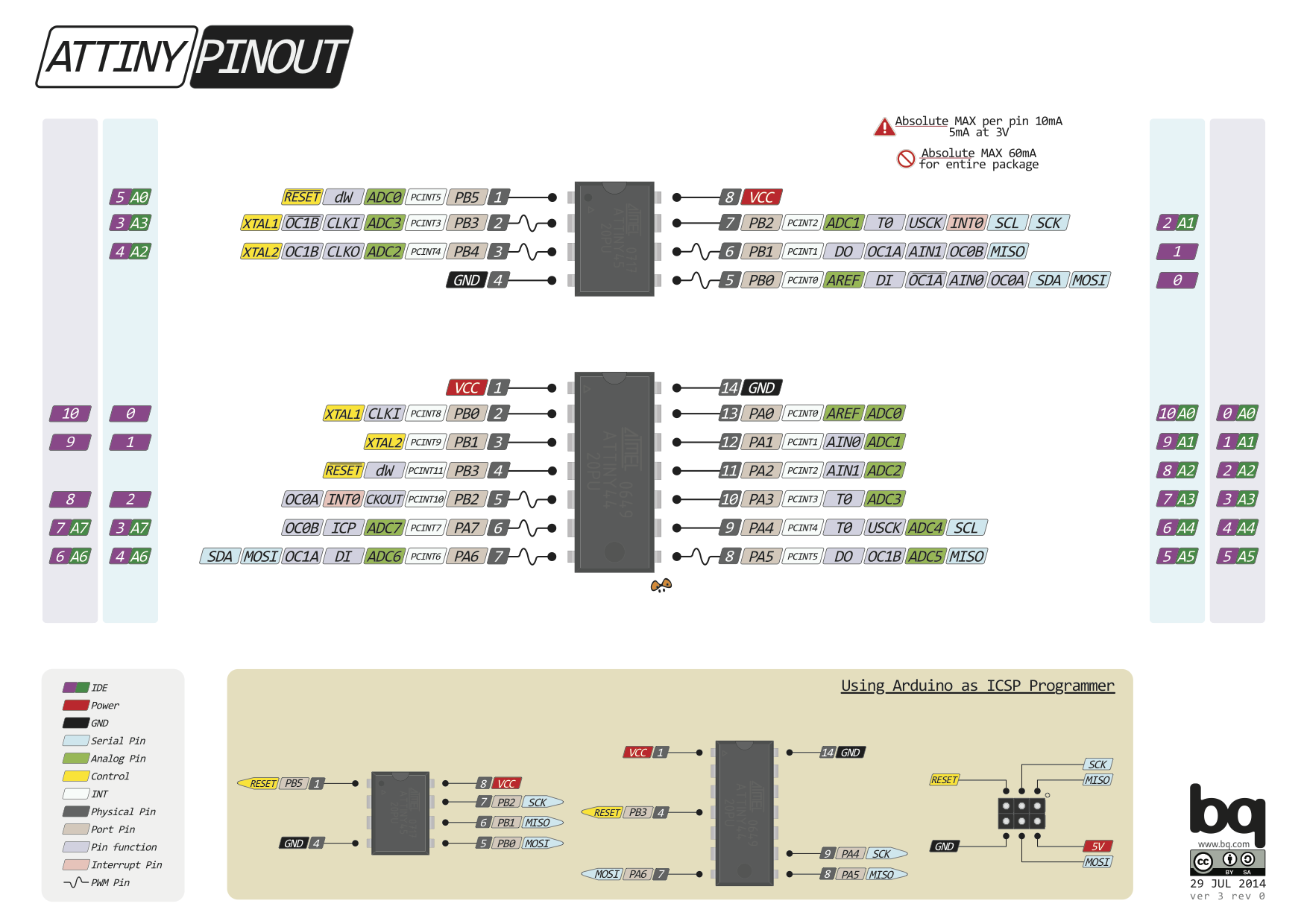
In this exercise we had to design the boards using Attiny 44. So I started with the datasheet from ATMEL. It seemed complex for a noob like me. Further I searched for the Attiny 44 pinout diagram and got some diagram that can be comprehensible to me. Sharing those diagram here. It clarified my idea about Arduino, Digital Pins, analog digital converters and ISP.
I further saw one video about using ATTiny 85 to understand its function as a MCU and how it can function in a circuit.
How-To: Shrinkify Your Arduino Projects by Make:
I believe now I can design and build my board with proper understanding of the components.
echo hello board
re-designing
I have planned to design my board with the following components:
- One LED that will lit up while the board gets power.
- One LED that will be lit up if the button is pressed.
The next step was to sketch the components and the connections in addition to the board we are given.
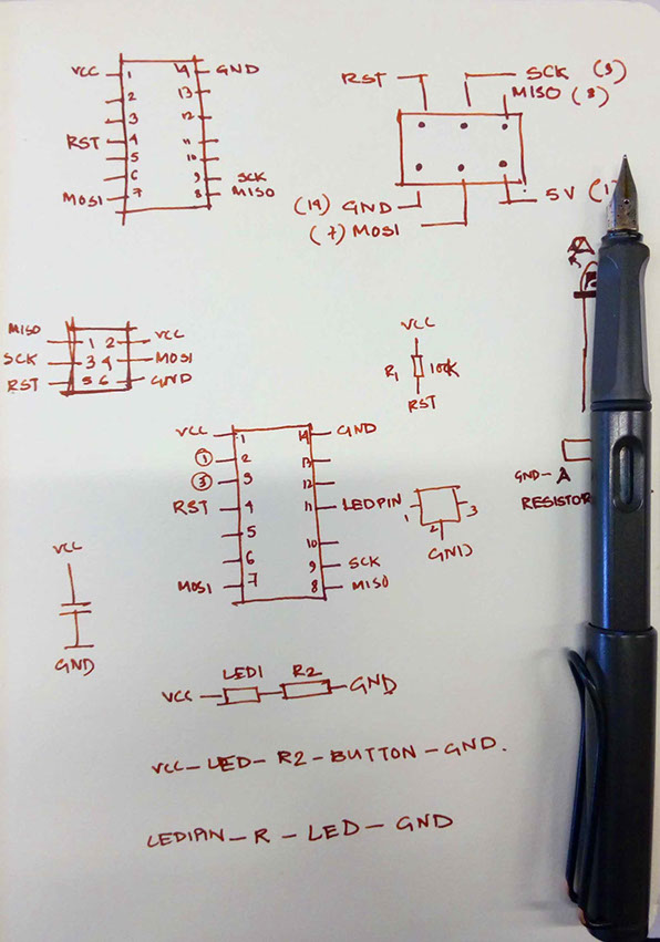
Sketches about understanding and re-designing the circuit.
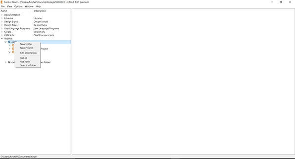
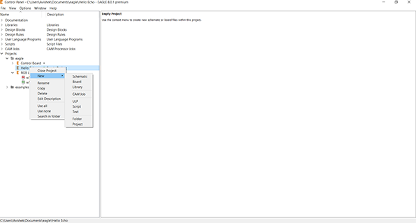
using autodesk eagle
for redesigning

In this week I had chose Autodesk Eagle to design to design the PCB for the assignment.
The collaboration between Fab Academy and Autodesk gave me a professional license for an year. Nevertheless, it is freely available to students. One can get it here.
To start with Eagle its good to start with the Fab Academy tutorial. I also followed tutorial of Jeremy Blum for a very hands on experience with Eagle through a video series of 3 videos. I found that very useful; the tutorials are shared below.
P.S. : It was known as Cadsoft Eagle few days back also till Autodesk acquired it. It's still the same tool with minute alteration here and there.
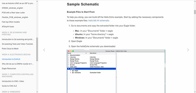
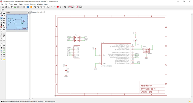
First I downloaded the schematic available in the Fab Academy website to see the basic before I start my own board. It helped me to identify the components. From the same page I downoaded the Fab Library for Eagle and placed in the C:\EAGLE 8.0.1\lbr folder.
It holds all the components required for the Hello FTDI board along with majorly used components in the Fab Academy course. Another file is also needed in long run. That is called the DRU file containing the design rules about the traces and gaps. One can download it from here.
The basic components of the the hello echo board are listed below:
- ATTiny 44 as MCU x1
- 6 Pin AVR ISP Header x1
- FTDI Header x1
- 20 MHz Resonator x1
- 1 uF Capacitor x1
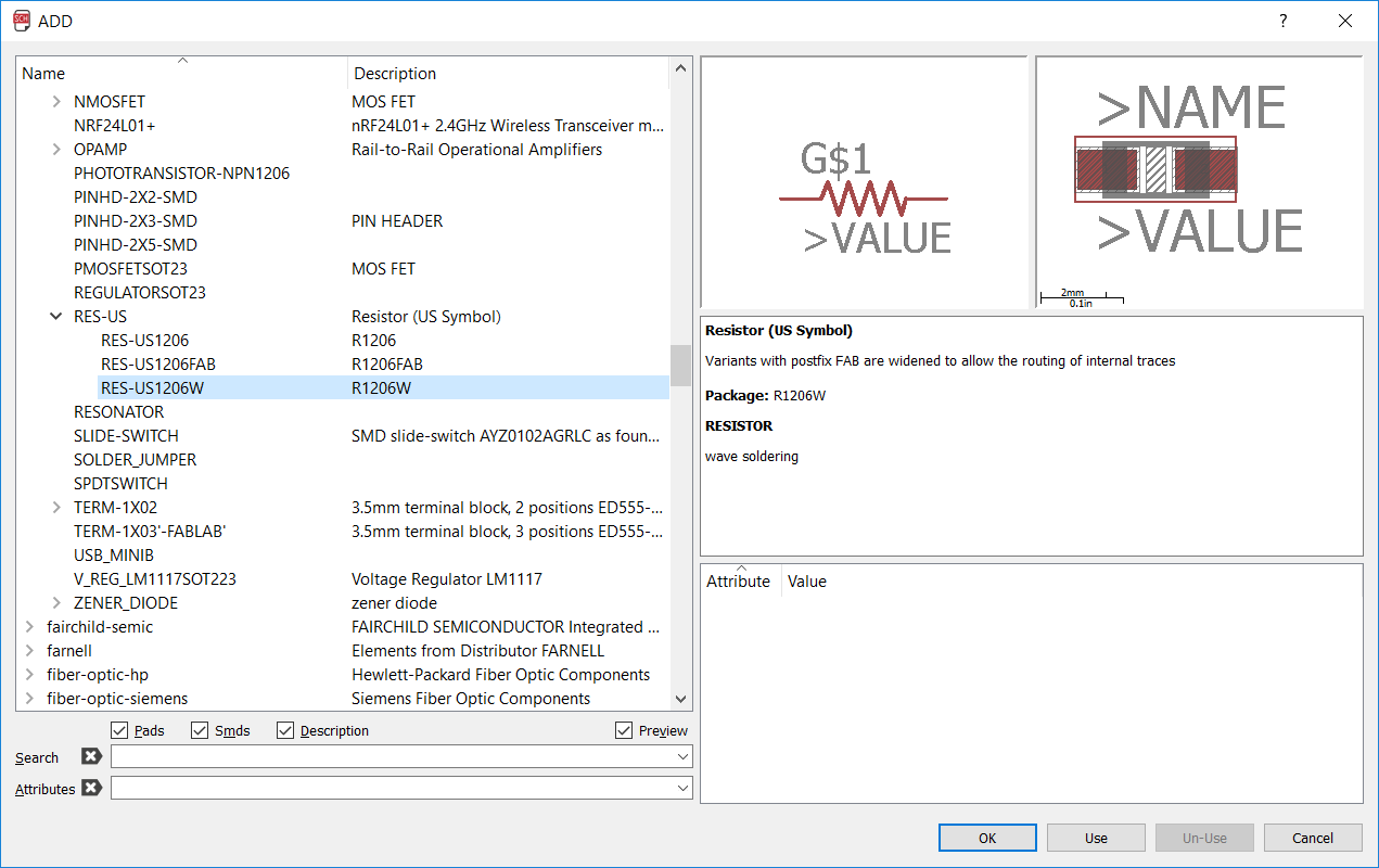
- 10K Ohm Resistor x1
In addition to that I am supposed to add few more components:
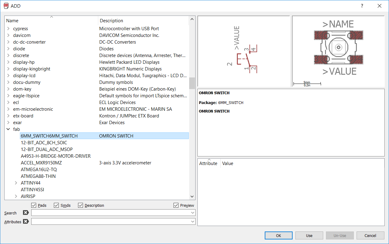
- Push Button x1
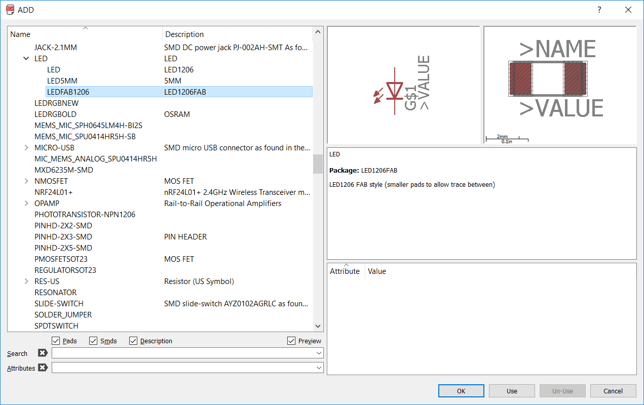
- LED x2
- 499 Ohm Resistor x2
- 10K Ohm Resistor x1
All of these components are available in Fab library. Their link and appearance are as follows:
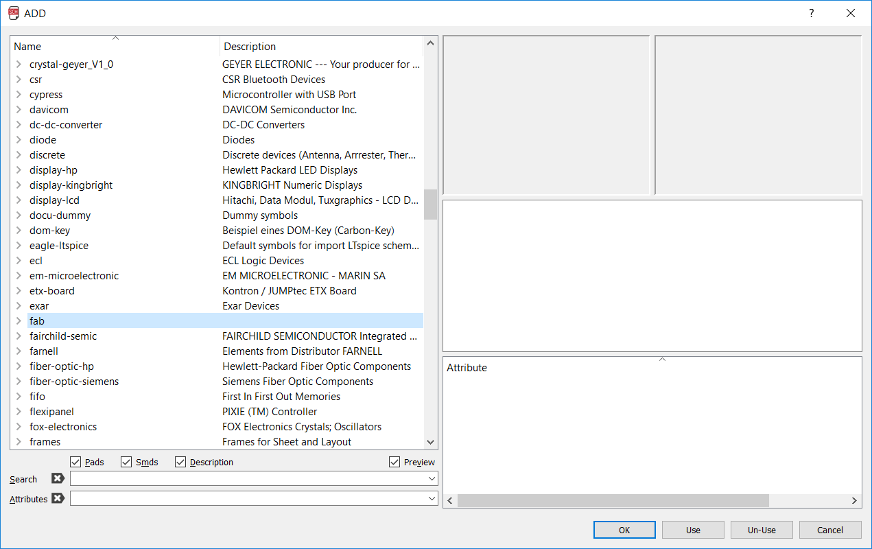
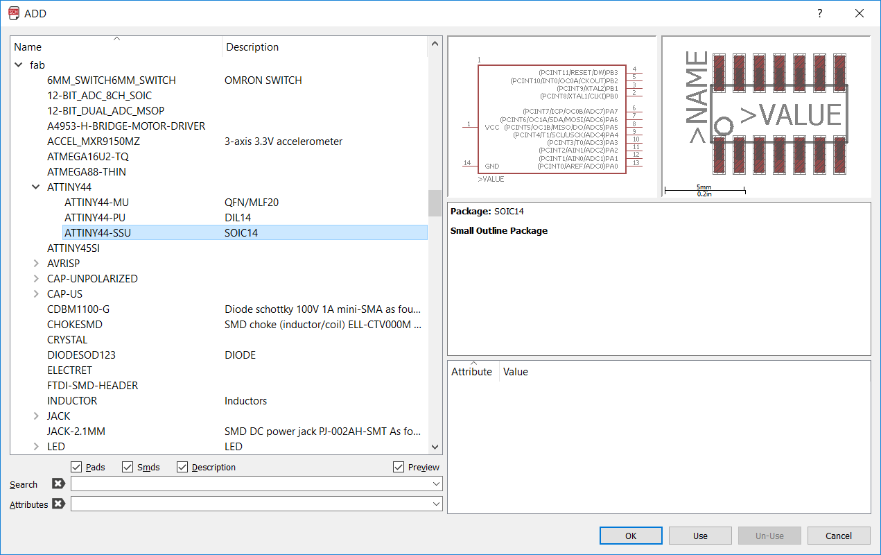
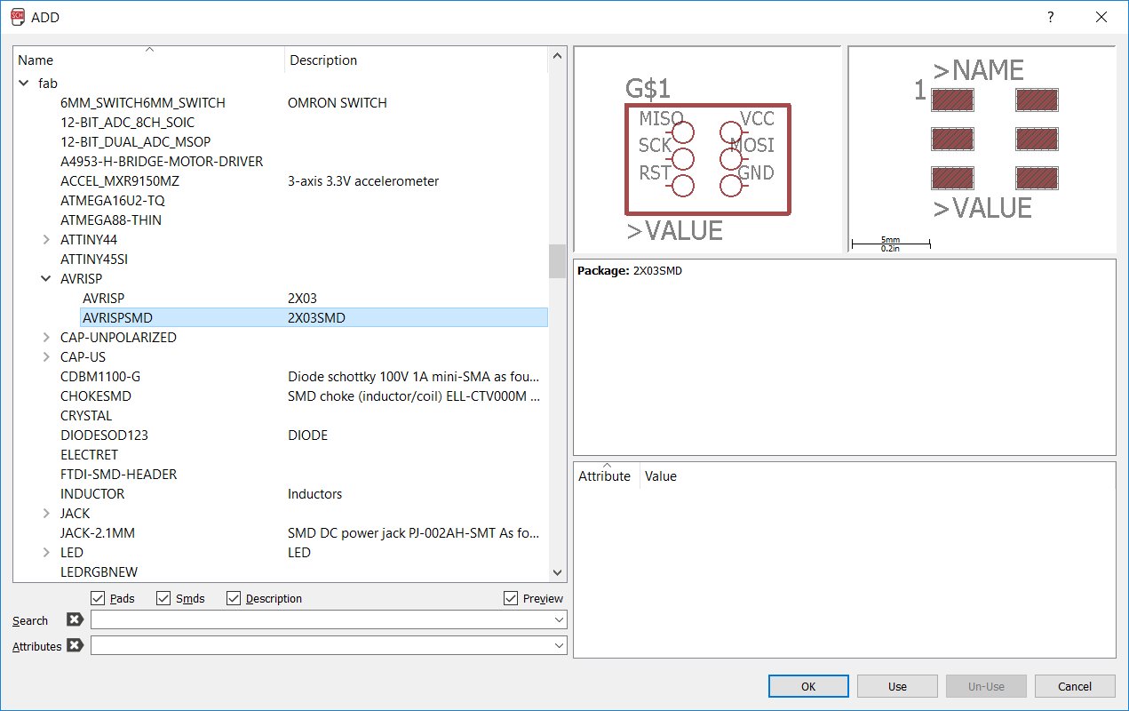
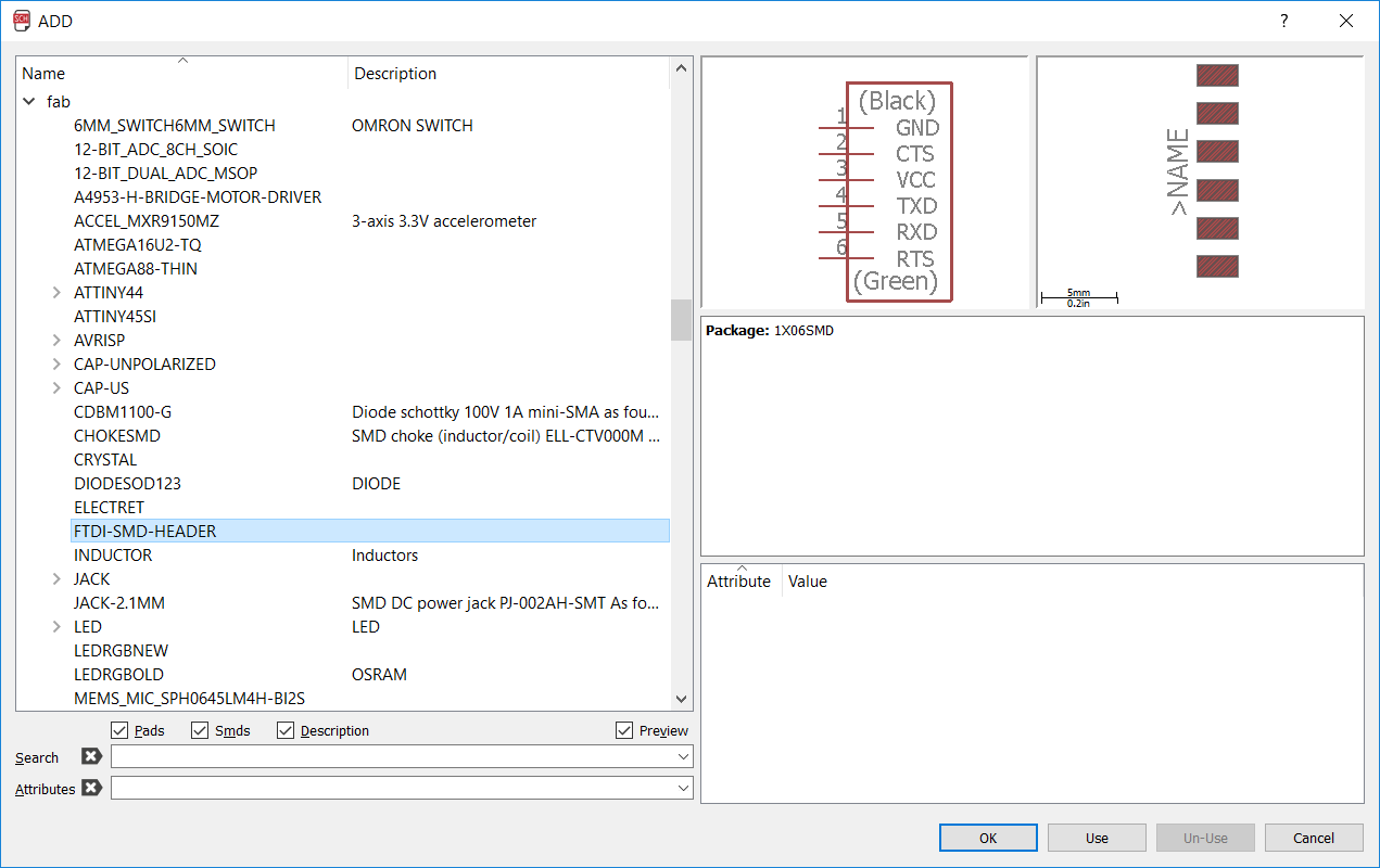
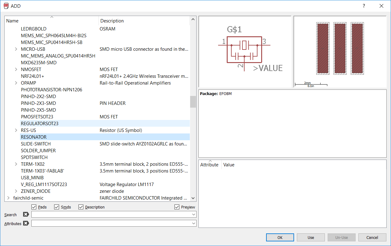
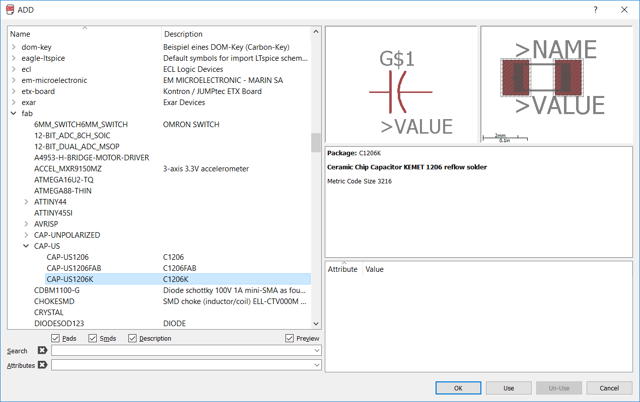
<
>
Components
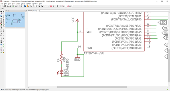
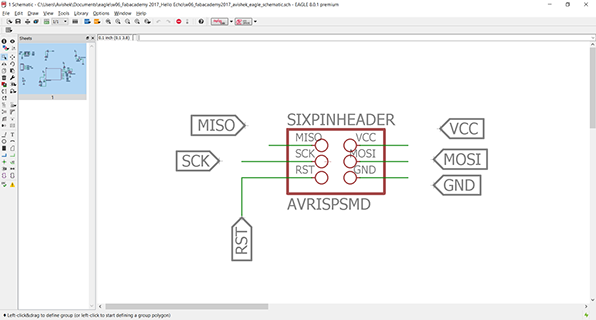
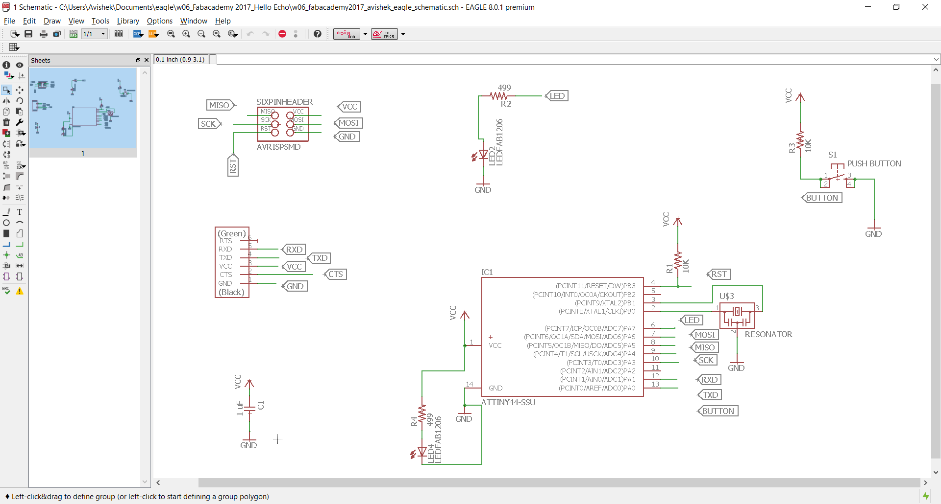
Now I place the components in the Eagle Schematic according to my need. And started connecting them. One way of doing is to connect the ends using Net. Another is to add text at ends possible and repeating the same text remotely.
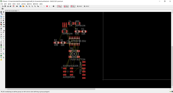
Once the design is complete it is time to go to board design. It can be done in 2 ways:
- File > Switch to Board
- Click in the switch to board icon just below View menu. (see the screenshot below)
It will pretty much look like this.
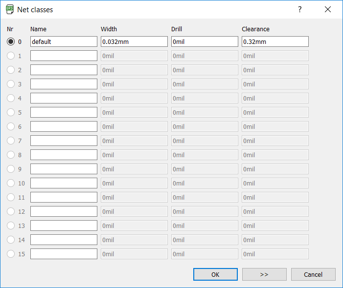
Now the task is to set the track width and clearance in the net class.
Go to File > Net Classes.. and set Width as 0.032mm and clearance as 0.32 mm. This value is prescribed from the DRU file.
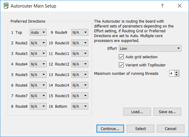
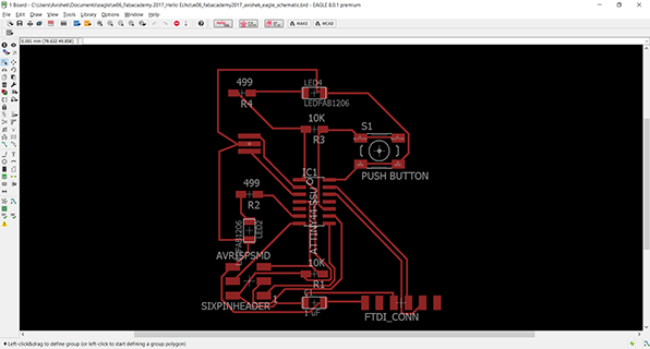
Now it is required to arrange the components and run the Autorouter. The following should be the setting and to keep in mind . Every other directions EXCEPT 'TOP' should be set as N/A (not applicable).
The first iteration I got is this. Not really the one I like.
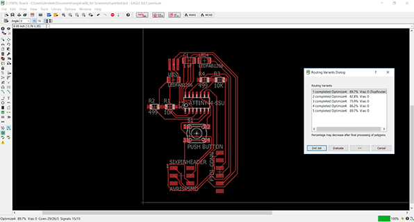
I saw a lot of crossing of lines in the board now.
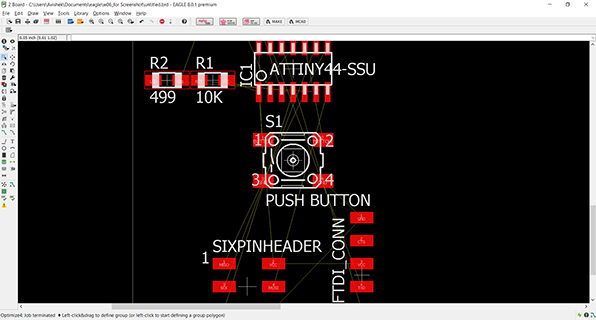
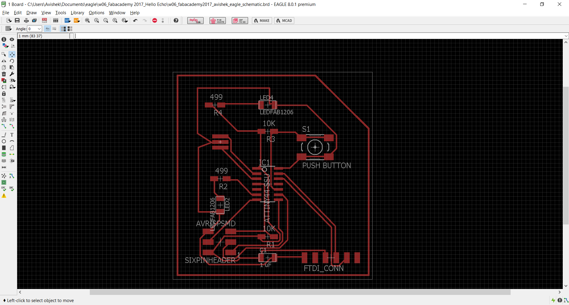
After spending some time I made some other layout and moved all the parts here and there to figure what is to be done and what is the best and came to this.
Now the things left are to export the trace and the outline. Before that I need to make a outline drawing.
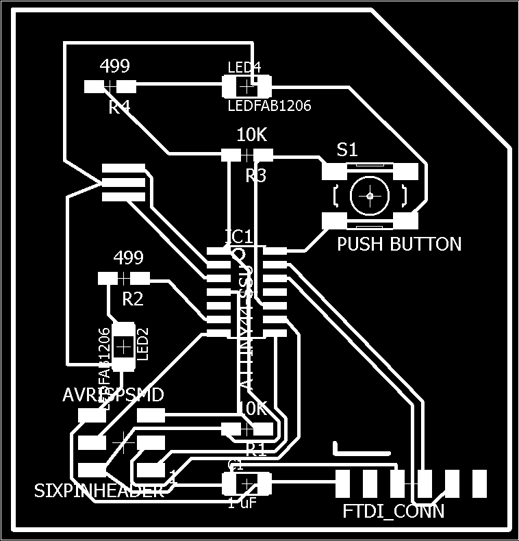
Now I need to export the files as PNG to be ready to be milled.
File > Export > Image
But before that I need to make sure only the 'TOP' layer is turned on. Otherwise we get result like this.
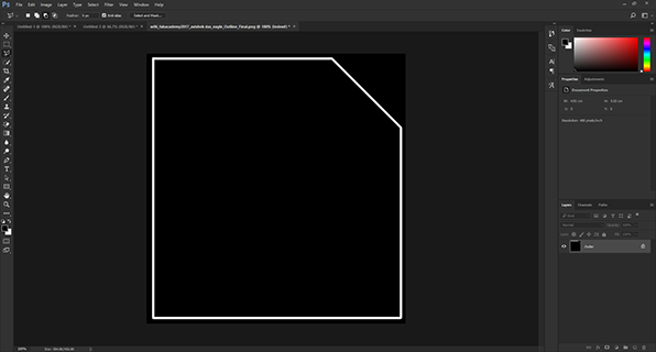
Now I took the file to photoshop and erased everything inside except the outline and filled the inside with white on whose outline the board will be cut in the Modela. This becomes my outline file to be milled with Modela. So these are the files.
Trace.
Outline.
My files for this week can be accessed here. It includes the Eagle files and the PNGs.
designing the
krab board
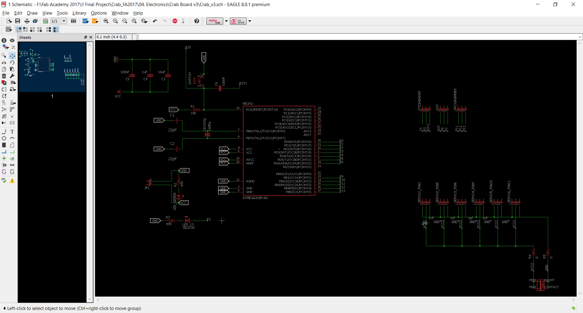
For the Robot Control, I needed a board that can run 6 servos and interfaces with grasshopper through FTDI. For this ATMega 328P-AU based board was needed to interface with Grasshopper with UNO based Bootloader.
So here I modified Danielle Ingrassia's Satshakit schematic to fit my purpose.
understanding
atmega328p
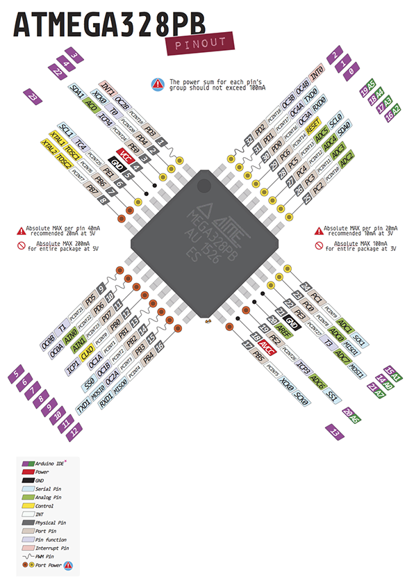
ATMega 328p AU is another processor from Atmel. But in comparison, much powerful than ATTiny 44. There are several advantages of this chip that makes me use this for the Robot Control Board (Krab).
- 6 Nos PWM pins; suitable for running 6 servo for each axes.
- Easy Serial communication .
- Can be used as Arduino Uno by burning Uno's bootloader.
- Simpler to code through Arduino IDE, Grasshopper, Firefly.
- More memory to store bigger firmata for serial communication.
My addition / alteration to the original board are listed below:
- Dedicated external 5V power supply for the Servo motor.
- Provision of Common ground with the External power and power from FTDI. ATMega 328P is powered using FTDI from computer but servos get power from 5V SMPS.
- Dedicated Programming pins. Separate from the normal array of pins.
- Dedicated FTDI Pin header as Reset Pins.
- Power supply pins are changed location (same as my input device).
- One LED is connected to pin 3 instead of 13.
designing in eagle
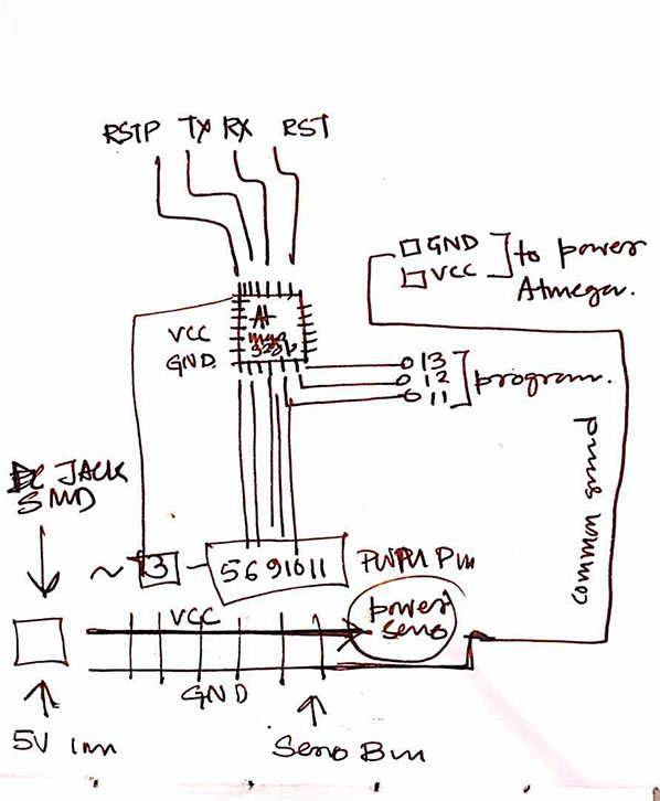
First I had sketched the schematic the way I wanted the board to be, before moving into Eagle for the final Design.
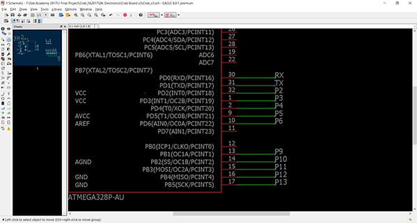
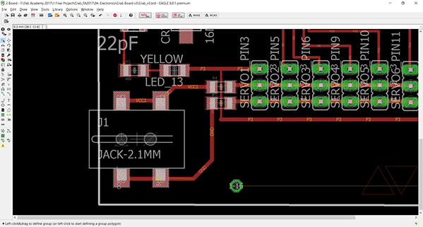
I needed the PWM pins of ATMega 328P for the Servo Control. So pin 3,5,6,9,10,11 were kept with Pin 2 and 4 for uno read in Firefly. For the Programming and data transfer TX, RX, RST and 12,13 pins were also retained.
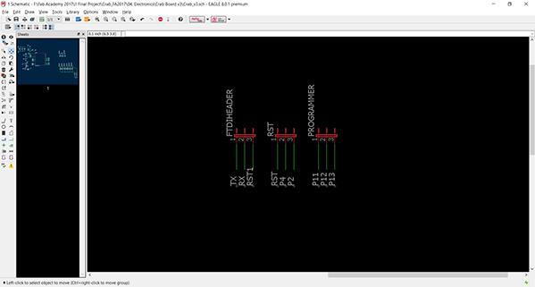
The header pins for the programming, FTDI and Reset Circuit.
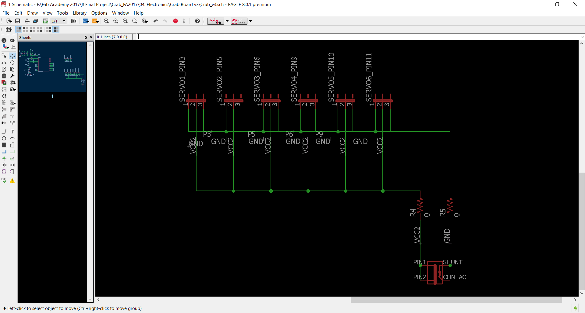
The Servo pins where the VCC is connected to external power supply, commonly grounded with the board ground and Signals are connected to respective PWM pins.
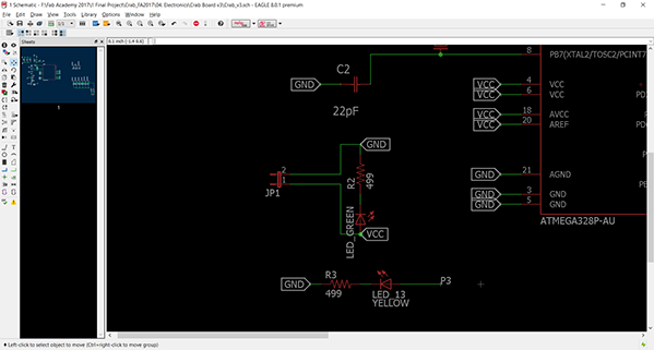
Header with the power and LED connected to Pin 3 instead of 13.
Header with the power and LED connected to Pin 3 instead of 13.
For the board design part the followings were done. (some similar things were done for the Input devices too.)
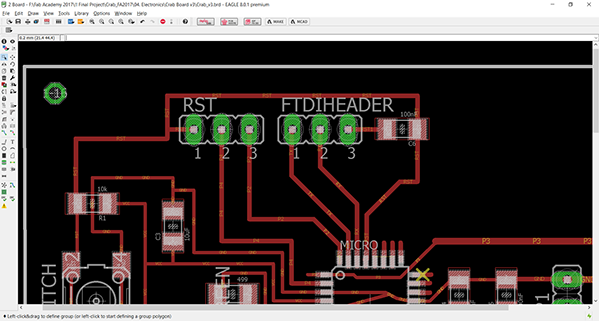
Separated FTDI and RST connector.
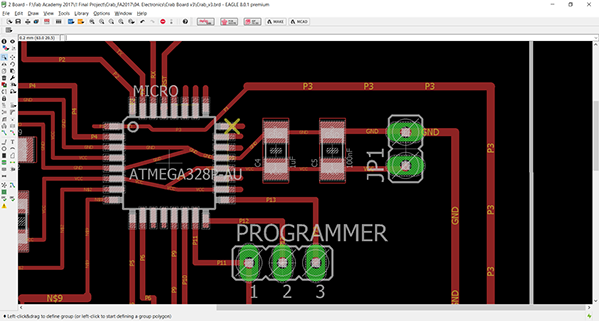
VCC for the ATMega 328P and common ground with the external power supply.
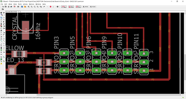
The PWM pins in a row with the external power source. For the Pin3 to connect in a same sequence VCC and GND are using a 0 Ohm resistor Jump.
SMD DC socket for the power to supplied to the Servos externally.
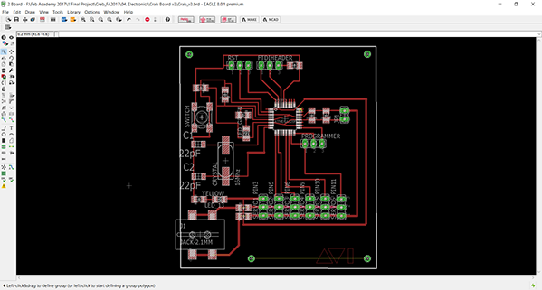
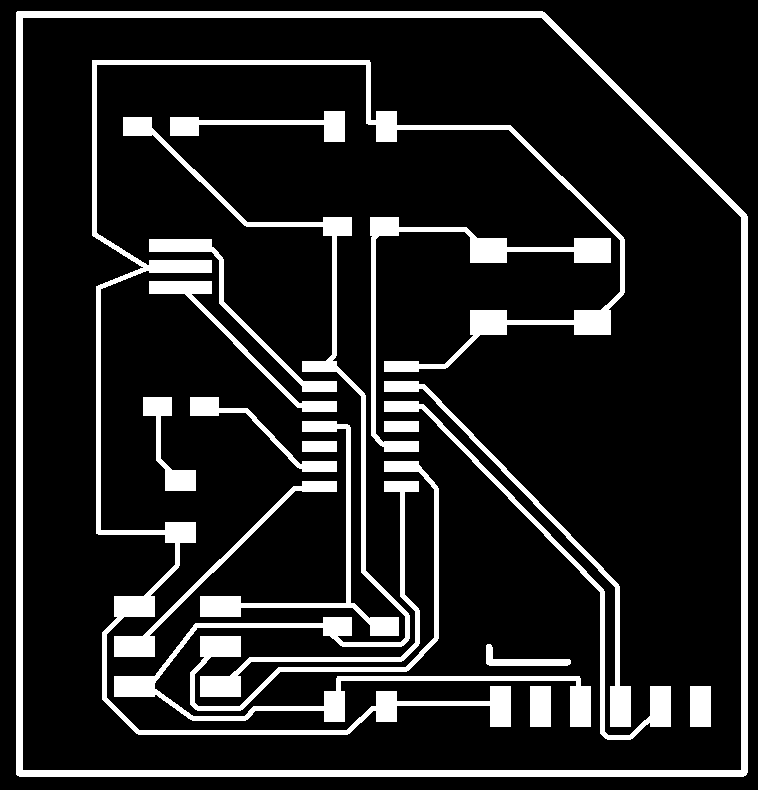
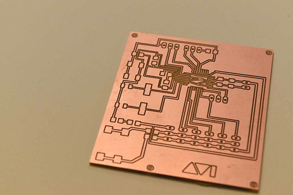
Completed board. Some vias were added to the board to us spacers in those to mount the PCB.
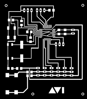

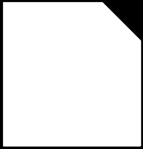
The mill trace and the Cutout board exported from the eagle for milling.
Before this version this board has under done 5 more version. Krab v5 was the stable board before that , but position of header pin has been finalized in this version.
Krab v5 board. partially damaged. Prone to wearing off track. So the logical part was to mill the new Krab v6 trace and cutout and make it into a functional board.
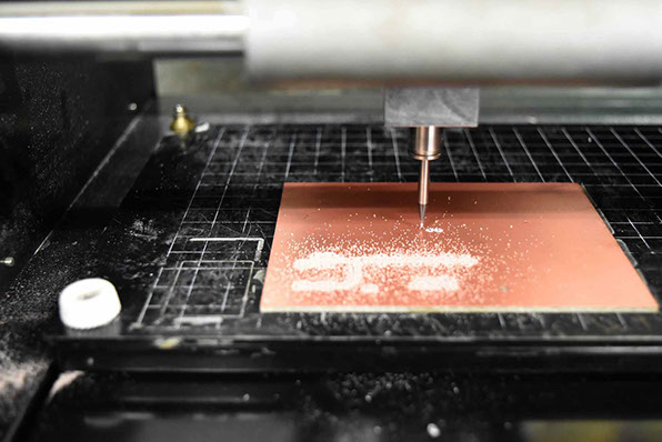
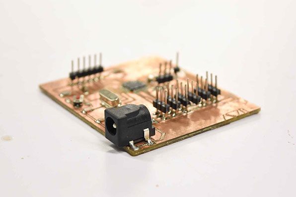
After the first milling i found some tracks are off and had to mill again.
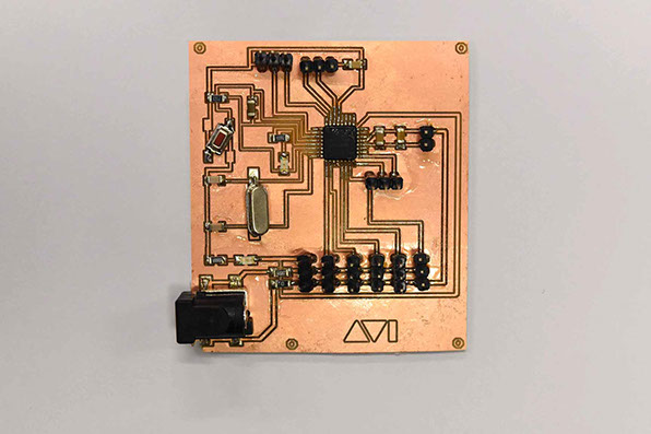
I got all the components in order an soldered them in order to make them into a functional board. The component list is as follows:
- ATMega 328P AU x1
- 16 MHz Crystal x1
- Button x1
- SMD DC Socket x1
- 10K Resistor x1
- 499 Resistor x2
- LED x2
- 0 Ohm Resistor x2
- 100nF Capacitor x2
- 22pF Capacitor x2
- 10uF Capacitor x1
- 1uF Capacitor x1
- 3 Pin header X 9
- 2 Pin Header x2
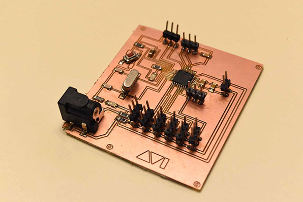
Hero Shot of The Board.
The working files for this board can be found here.
go to WEEK 7 >>
Avishek Das | 2017 | FabLab CEPT