week 4
Electronics Production
ASSIGNMENTS:
- Describe how to make and program the FabISP Board.
- Explanation of problems occurred (if any) and solution to them.
- A 'hero shot' of the board.
micro milling
fab isp
weekly work
final project
First stage of this week's assignment was to mill the FabISP using a FR1 Board in Roland Modela MDX-20. For this, I used the FabLab CEPT ISP designed before. But in turn I tried the original FabISP also. The trace and the interior PNG could be accessed from here. Now its time to move to Linux and use Fab Module with Roland Modela MDX-20 to mill the circuits. The procedure is well documented in FabLab CEPT's previous student Rudrapalsinh and Tapan, I took their reference. It can be found here. I am new to Linux operating system and using it almost first time, so I followed the steps religiously.
FabLab CEPT
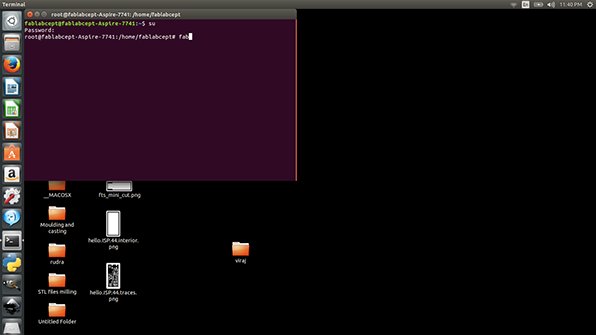
Setting up Fab Modules in Terminal. type SU to get access as super user and Fab after that.
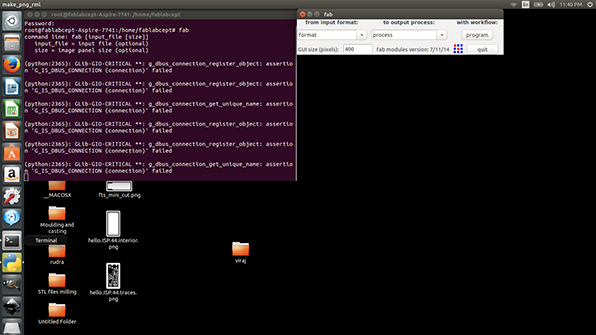
Fab Module is loaded. The interface has come up on to the right.

We need to select Image input formate and Roland MDX 20 from the machine/ process list.
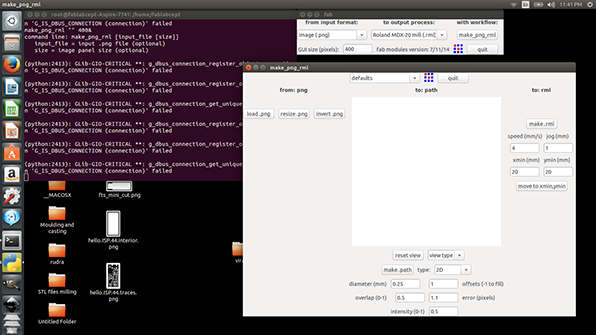

We attach the 1/64 inch bit and select the PNG of traces.

The Window should look like this now and we need to set the parameters now.
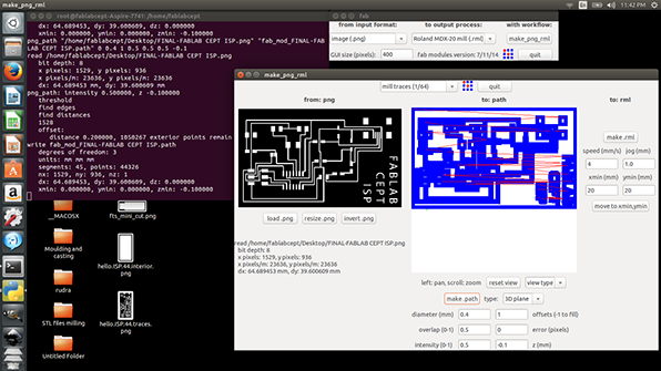
Then click on make.path to generate the toolpath.
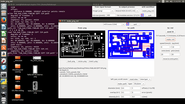
Now make.rml is pressed to make the GCODE compatible to Roland Milling machine.
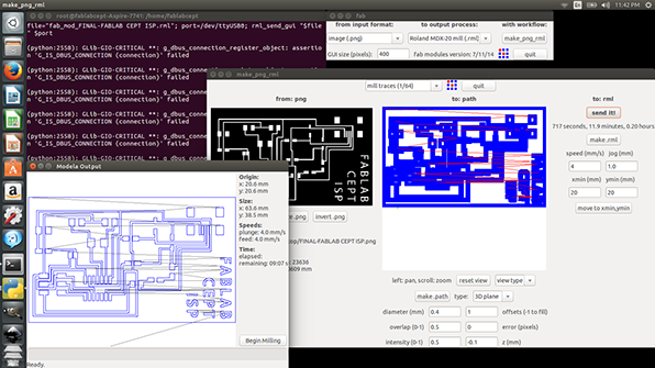
It is ready to mill the PCB and begin milling is pressed. Make sure that Roland Modella is connected and not in View Mode.

Similar process is followed with Interior PNG but with 1/32 inch bit to cut the extents of the board.
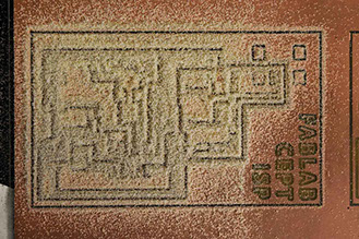
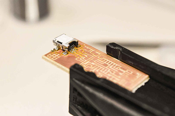
This is a board look like before it is cleaned for soldering. This amount of material should be scooped out to make sure the copper is properly milled.
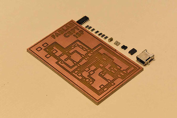
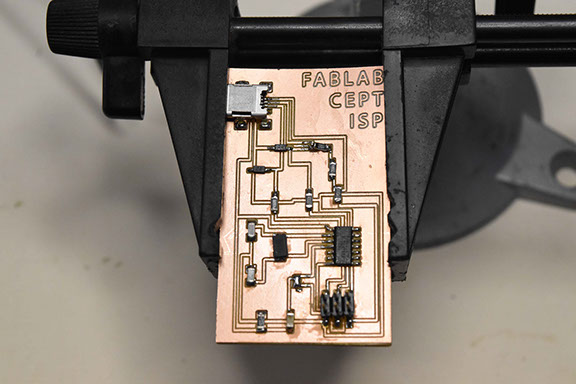
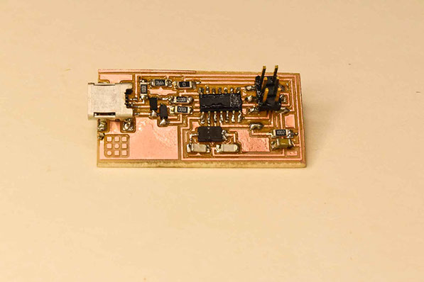
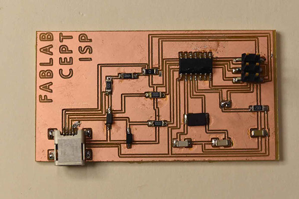
This is the board I milled first and with all the necessary components to be soldered.
The components for the FabISP are listed below.
- Micro USB Header x1
- ATTiny 44 x1
- Zener Diode 3.3v x2
- Crystal 20 MHz x1
- 1 MicroFarad Capacitor x1
- 10 PicoFarad Capacitor x2
- 0 Ohm Resistor x2
- 100 Ohm Resistor x2
- 1000 Ohm Resistor X1
- 10000 Ohm Resistor x1
- 499 Ohm Resistor x1
- 6 Pin Header x1
Now its time to solder the components on the board.
But I made a mistake of swapping the place for 1 MicroFarad Capacitor and 10k Ohm Resistor. But eventually corrected it.

I tested the Board using AVR MKII programmer and it gave proper Green Light on the one side connection and Orange Flashing on the other side connection. I proceeded to the programming the board. I downloaded AVRDUDE and GCC and the FabISP firmware for programming.
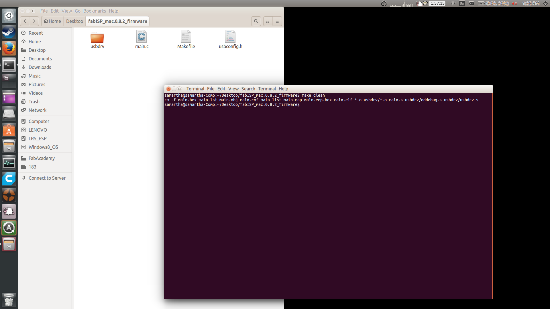
I went in to the firmware folder and accessed Terminal from that location.

I wrote : Make Hex and it created the necessary file.

Next step was to insert the command : make fuse

now for Programming the board I make the step further. Make Program. Everything seemed to function properly.
It did now show up in the list USB and even in a windows machine. I tried several times but failed. So I milled another FabLab CEPT ISP board and Original FabISP board and proceeded with original FabISB board.
It showed the same problem. I started with the other board.
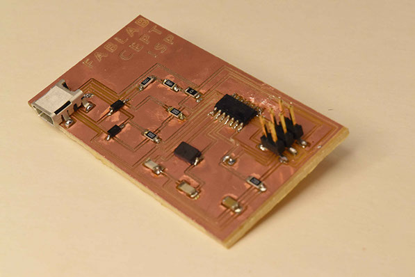
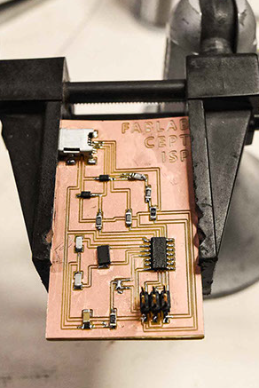
So this is the board and it is noticed that soldering quality is also improved with practice.
And this board got programmed perfectly and showed in my Windows PC too.

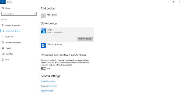
I made a video and it proves the Board works with AVR MKII and a signature sound of connecting a device on Windows 10. The 'hand' you will be seeing in the video is of Chandni Chhabra. She helped me to make the video.
The Hero shot of the boards are as follows.
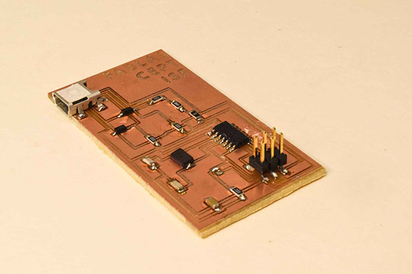
The perfectly working one.
The PLAN view.
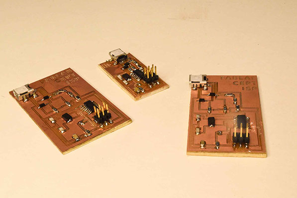
All 3 Boards i milled and made. But the rightmost one is the working perfectly.
VISIT
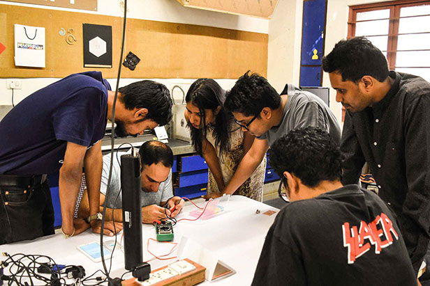
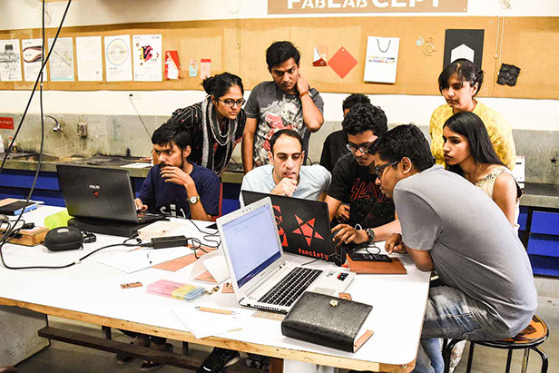
by our mentor
Surprisingly this week we got a visit by our mentor Ohad Meyuhas. We spent an amazing time learning about ISP, 3D printing and much more.

go to WEEK 5 >>
Avishek Das | 2017 | FabLab CEPT