FabLab Cept
NETWORKING AND COMMUNICATIONS
For networking and communication , I decided to go for Half-duplex serial communication between an Input and Output devices. Input device was Distance sensor and Output device was RGB led.
INPUT DEVICE
With help from Gautam and Mohit, I designed a Distance sensor board. I had earlier designed a distance sensor board in previous week but could not use it for networking since it did not have Rx/Tx for communication.
1. The first step was to design the board in Eagle. I took my old board and added Rx,Tx,VCC and GND pins.
Over all the board had following components:
1. Attiny 44ssu
2. 1x6 pin male header for Distance sensor. However I used only 4 pins
3. 2x3 pin male header for AVRISP
4. 1x4 pin male header for Rx,Tx,VCC and GND.
5. 1 micro F capacitor.
Following images show the process I followed. Detailed process of Eagle and milling can be seen in the previous weeks.
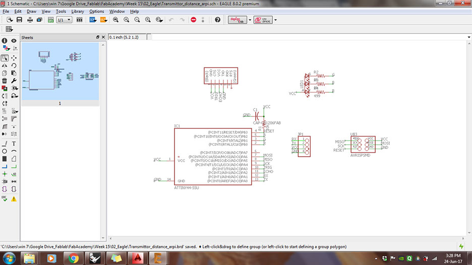
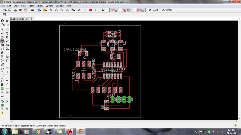


First step was to put Rx,Tx,VCC and GND in the board developed for Input device
Arranging the position of this 4pin header on the board.
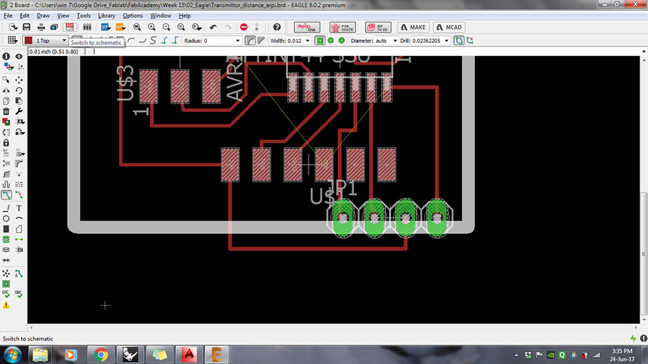
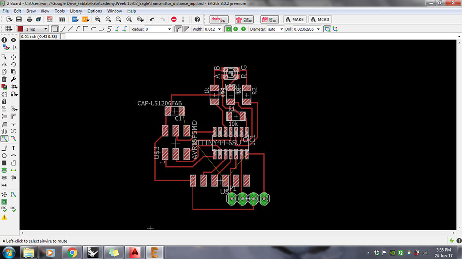
GND connection was still not made. Hence I decided to add a zero ohm resistor over the paths.
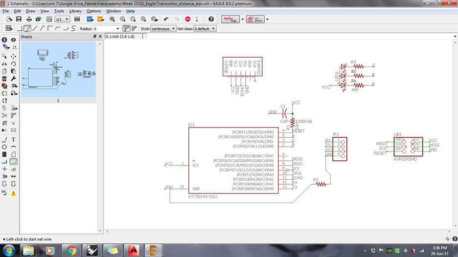
Here, zero ohm resistor is added in the schematic.
Board showing the final connections. Here zero ohm is added to conect the GND to 4-pin header.
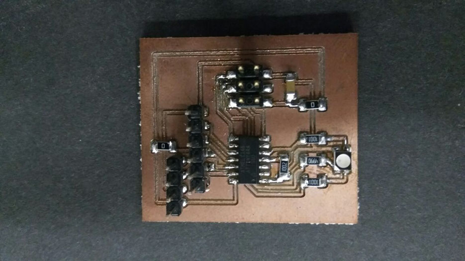
Milling the board using 1/64th bit
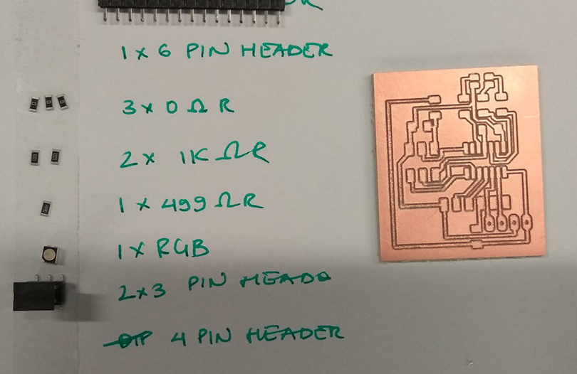
Once milling was done, the components required for soldering were arranged and the board was soldered.
This is how my soldered board looks like.
9 - 9
<
>
Next I checked if the board was working individually.
For this I tried the following codes
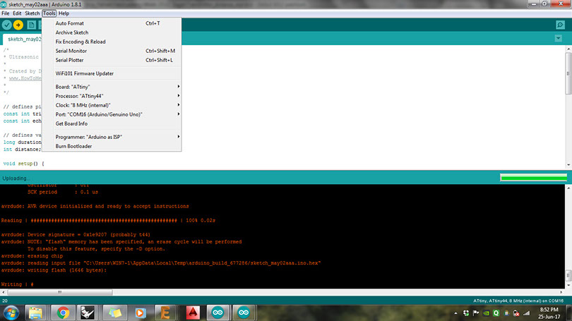


First step was to run Arduino as ISP and then burn bootloader for Atitiny 44SSu
First step was to put Rx,Tx,VCC and GND in the board developed for Input device6
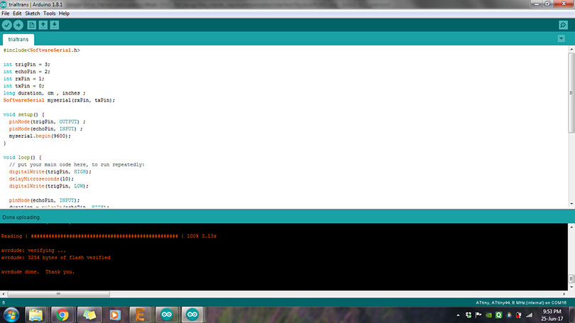
Defined Rx, Tx, Trig and Echo, where Trig is output and Echo is input. Mohit helped me with the coding of this board.
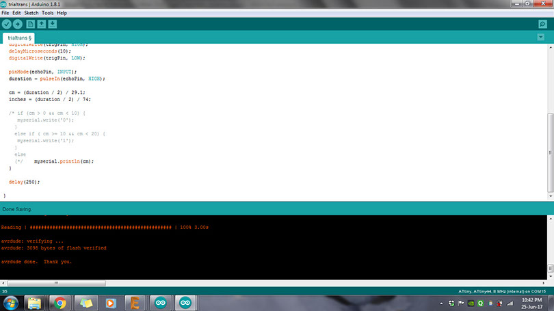
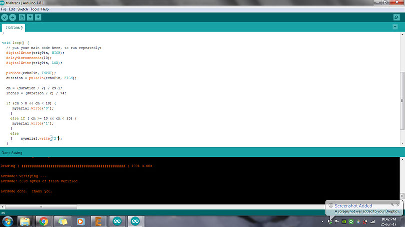
With the first code, I could get distance values in cm on the serial monitor.
For 3 different LEDs to blink, I needed 3 different values. So I gave "0-1-2" values to different range of distances.
5 - 5
<
>
Video showing distance in centimeters.
Networkings_input_01 from ARPI on Vimeo.
Video showing distance remaped to "0-1-2" as output.
Networking_input 02 from ARPI on Vimeo.
OUTPUT DEVICE
For output device, I used the board I made in previous week's assignment, which can be found here.

The code for LED was written to blink in different colours responding to input in the form of "0-1-2".
However, when the code was run later using networking, it did not work. Then I realised that since we are already providing VCC in common pin, we need to give digitalWrite as "low" for the colour that we want to blink.
Hence, the code was corrected as below. The code can be found here

Next I used an FTDI cable and connected its Rx,Tx,VCC and GND to the input device board and the networking was established
networking_final from ARPI on Vimeo.
Next, to add more boards, I decided to add more values from my input device.
I used my "hello echo" board which I made in previous week. Details can be found here.
The idea was to allow more boards to be connected. For this, one option is to call each board by giving different addresses from the computer, and the next option, which I chose, was to allow the input device to call for different boards and also define the colours of RGB led in the first board.
Following diagram shows the connections required between the boards, and Input-Output values
Master
Slave
Slave
Rx
Tx
Tx
Rx
Tx
Rx
Distance sensor
RGB LED
Hello echo "LED"
Value = 0
Output = Red
Value = 1
Output = Green
Value = 2
Output = Blue
Value = 3
Output = Led
My distance sensor code currently gave me values as 0-1-2. Here, value "0" would light up Red colour on the RGB board, "1" would light up Green and "2" would light up blue. So, again I changed the distance sensor code and increased its range to give an additional value "3". This value will give signal to light up the Led on "hello echo" board. Similarly the code can be modified to give additional values and signals can be given to additional boards as and when required.
Here is how the code looked like

I uploaded the code successfully to obtain 0-1-2-3 as values for different range of distances. I checked it on serial monitor first, before attaching the boards to the other board.
distance_including 0-1-2-3 from Arpi on Vimeo.
Next step was to write a code for "hell echo" led to light-up when it gets signal "3".
Here is how it looked like.

Next step was to write a code for "hello echo" led to light-up when it gets signal "3". Here is how it looked like. The idea was to see the LED light up once you give the value "3" from the computer. Later on when all the boards are connected, this value will come from my input device.
VID_20170709_155002 from Arpi on Vimeo.
Here is how my code for "RGB Led" looked like. In terms of logic, there was not any changes, I only changed the variable name.

I checked if my code was working individually. It would give me red, green, blue outputs for 0,1,2 respectively. However, while making the video, I by mistake pressed 2 numbers together, 0 and 1, and surprisingly it gave my violet colour. Check out the video below.
VID_20170709_143827 from Arpi on Vimeo.
Finally, since all individual codes were uploaded, I connected all 3 boards and FTDI, to check if my connections were working
VID_20170709_160928 from Arpi on Vimeo.
All files can be found here.
