FabLab Cept
Laser Cutting and parametric design
For experimenting with laser cutting, I decided to use 2.5mm mdf to determine the size of the grooves for press-fit models. For this I used grasshopper scripting to get a polygon where the number of sides can be modified and each side had a groove with increasing width of groove. Since, I was using 2.5mm mdf, my starting value for groove width was 2.3mm , however the script allows to change the start value if someone wants to change the thickness of the mdf.
I chose an Octagon so that I could test 8 different groove width. I printed 9 of these .
The text and the polygon are put in 2 different layers. This will help in giving 2 different types of cut depth, because I wanted to score the text and full cut the polygon.
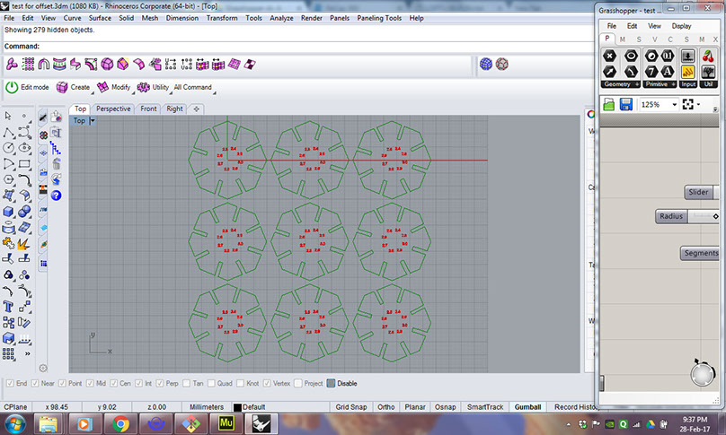
Here the most important thing is to set the line-weight of the used layers to "hairline".
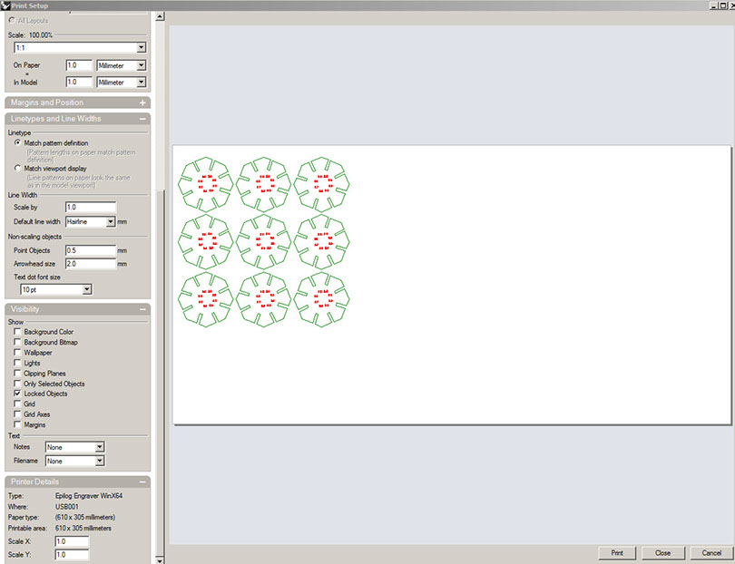
Next command is for print : ctrl+P.
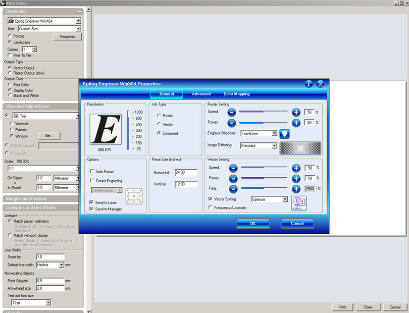
This opens another window where you adjust the settings for printing.
Clicking on "properties" opens the blue window where you can set options related to your laser printer.
I selected the job type to "combined" which gives a combination of raster and vector, because I wanted to use "Raster" settings for scoring my text and "Vector" settings for cutting my polygons.
Next I set "Piece size" to 24*12 inches which is the bed size of our laser cutting machine.
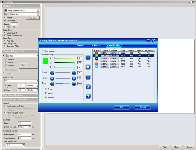
The next step is to go to "color mapping" settings.
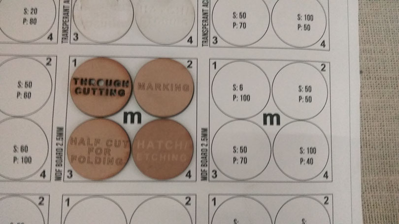
The basic concept is that the printer uses the colour of the object to control the sequence, speed, power and frequency of cutting the object. The cutting sequence starts from red then green and so on to cyan. Since I wanted my text to be scored before my polygons get cut, I put them in the red colour and the polygons in green colour. The power and speed settings were determined by the group assignment that we did for this week.
Once the settings are done, I selected the object to be printed and set the scale to 1:! and gave print.
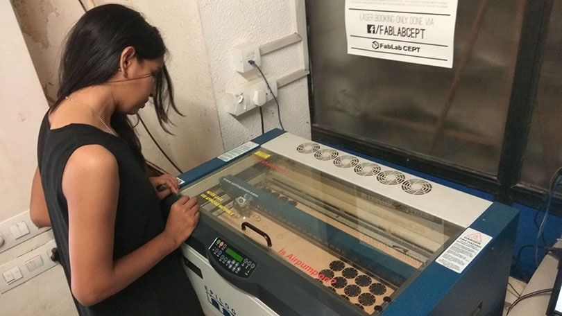
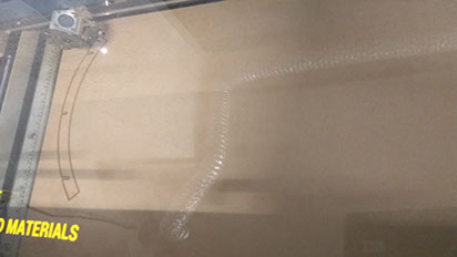
Since I was using a used mdf sheet, I needed to change the origin of the laser machine.
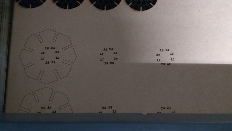
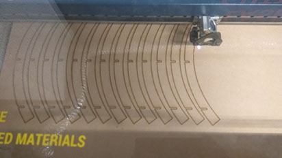
Once the cutting was ready, I tried connecting the grooves of same size to each other.
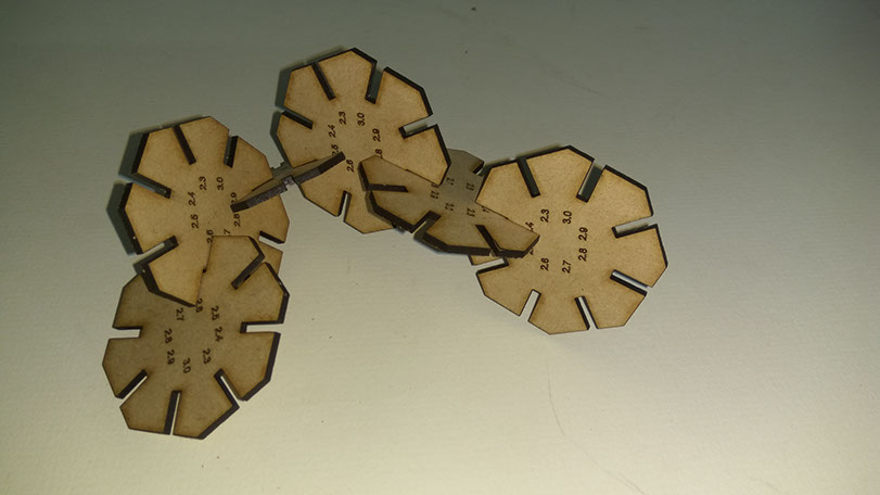
I observed that for a 2.5mm mdf, 2.3mm groove was inadequate, while 2.4mm grooves fit perfectly into each other. 2.5mm groove also fit but it was slightly loose while anything above 2.5mm was loose enough for the components to slide out of each other.
Hence for the next exercise I decided to go with 2.4mm groove.
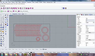
So for this week, I decided to make a simple object made by adding curved strips radially. To design a parametric model, I used grasshopper plugin for Rhino.
The design had following parameters:
1. radius
2. Number of ribs
3. Height of strips
4. z-coordinate of Location of arc interior point
5. x-coordinate of Location of arc interior point
6. Number of circular connectors
7. Width of the ribs
1. Radius
2. Number of strips
3. Height of strips
4. z-coordinate of Location of arc interior point
5. x-coordinate of Location of arc interior point
6. Number of circular connectors
7. Width of the ribs
Once I finalized on the different parameters in grasshopper, I baked and unrolled the surfaces in rhino. And then repeated the process of laser cutting which I used earlier for testing the groove width. Once I had the laser cut strips and the circular connectors ready, I could easily assemble them.
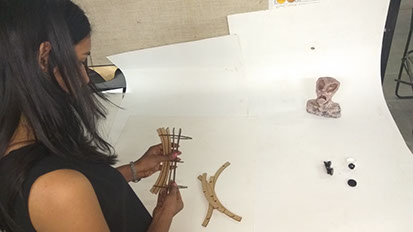
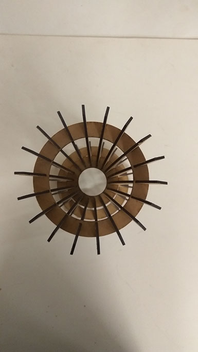
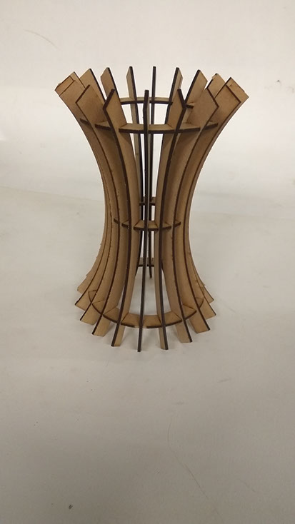
This is how my final model looked like.
Design files can be found here.