Week 10
Output Devices
The tenth lecture on Wednesday March 29th was about Output Devices: LEDs (basics, RGB, arrays), video, speaker, motors (DC, servo, brushless, stepper), relays. Assignment given by Neil for this tenth week was:
- Add an output device to a microcontroller board you've designed and program it to do something
Designing a microcontroller board including a servo motor control
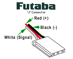
Between the various output types described by Neil during Week 10 lecture, I decided to focus on the control of a Turnigy TGY-MG90S servo motor (13.4g weight - 1.8-2.2kg torque - 0.10sec/60° speed), thinking it could also maybe useful as an output for my Mailplus Final Project (e.g. to raise and tear down a possible mailflag, but on this point I'm still in doubt, since mailflags are used in U.S. to communicate presence of outgoing mail, not incoming mail as in my purpose). A rotary servomotor is an actuator that allows for precise control of angular position, velocity and acceleration; in general it consists of a motor coupled to a sensor for position feedback.
Servo Pinout
Starting point for this assignment was the previous built echo hello-world board; used KiCAD EDA, opened Eeschema Module
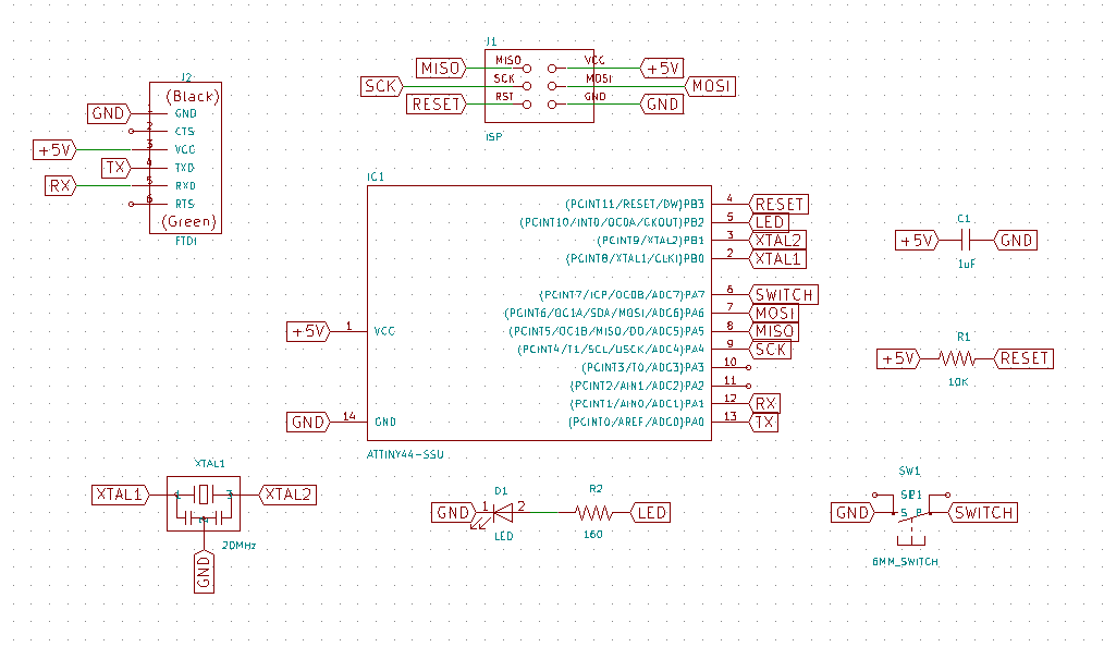
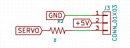
Since servo motor control is based on PWM (Pulse-Width Modulation, a technique for getting analog results with digital means), I went on checking ATTiny 84A datasheet, and finding Ports with PWM capabilities: Port PA5 (OC1B, Pin#8, already used by MISO), Port PA6 (OC1A, Pin#7, already used by MOSI), Port PA7 (OC0B, Pin#6, already used by Switch); Port PB2 (OCOA, Pin#5, already used by LED on the hello-world board). I decided to use Port PB2, Pin#5 to put the servo header control (I used a 01x03 connector) instead of the LED output: starting from the central one, I connected the Pin headers to +5V, GND and Port PB2, Pin#5 (renaming it "SERVO")
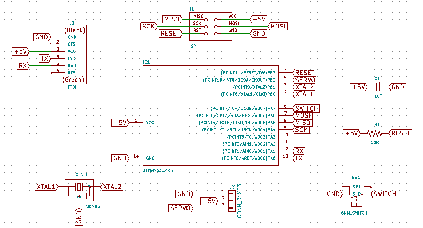
Since it would be very difficult (not to say IMPOSSIBLE) to route the tracks with a single sided SMD board like this without crossing the routes, and as in my previous Fab Academy assignment I wanted to route it manually through the KiCAD PcbNew Module, I was looking for an easy method to cross routes and the result turned out to be to add a Zero Ohm Resistor to the header schema:
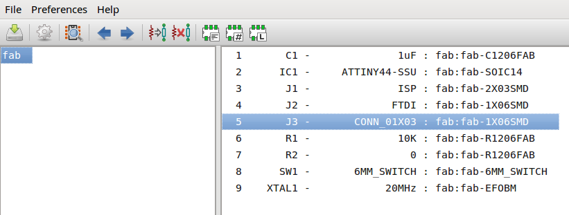
Then as usual, I went successfully through automatic schema Annotation, Electrical Rules Check (ERC) and, before exporting the NETlist, I associated components and footprints from libraries using KiCAD cvPCB Module; since in fab library, the only one I imported and used, I could not find a 01x03 connector header I associated it to the 1x06SMD footprint:
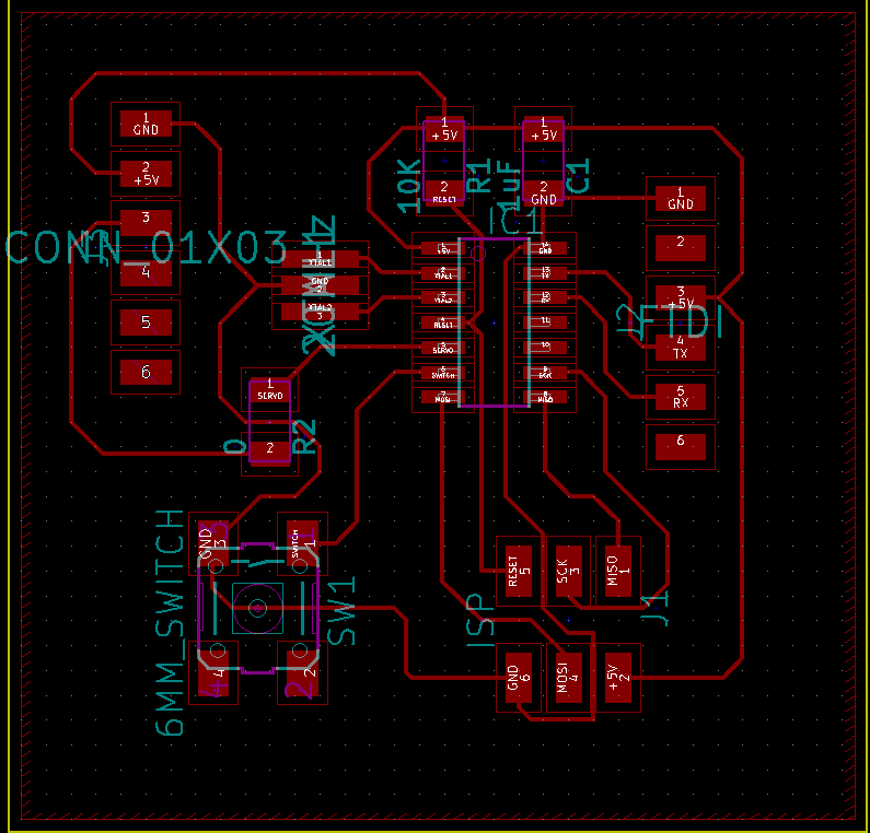
Here's the manual route result:
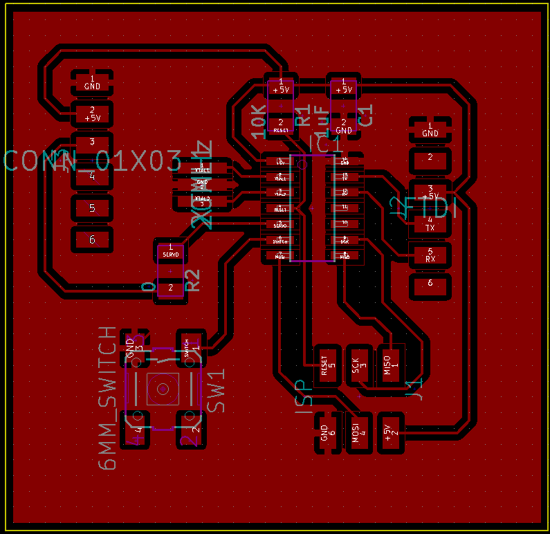
Here's with the filled zone, before SVG export
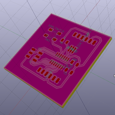
Here's is the KiCAD 3D render output

About the firmware I took inspiration from Arduino Sweep tutorial, then wrote the following code with Arduino IDE. I slightly modified sketch readapting PINs to ATTiny pinout, then I programmed the button to execute one single sweep when pressed.
/*
 * Based on Servo Sweep example code
 * by BARRAGAN <http://barraganstudio.com>
*/

#include <Servo.h>
#include <SoftwareSerial.h>

const int buttonPin = 7;

Servo myservo;  // create servo object to control a servo
SoftwareSerial mySerial(1, 0);

int pos = 0;    // variable to store the servo position
int buttonState = 0;

void setup() {
    // initialize the pushbutton pin as an input:
    pinMode(buttonPin, INPUT);
    digitalWrite(buttonPin, HIGH);

    // attaches the servo on pin 5 to the servo object
    myservo.attach(5);
    myservo.write(pos);

    // initialize serial interface
    mySerial.begin(9600);
    mySerial.println("Output device: servo");
}

void loop() {
    // read the state of the pushbutton value:
    buttonState = digitalRead(buttonPin);

    // check if the pushbutton is pressed.
    // if it is, the buttonState is LOW:
    if (buttonState == LOW) {
        mySerial.println("Button pressed, executing servo sweep!");
        for (pos = 0; pos <= 180; pos += 1) { // goes from 0 degrees to 180 degrees
            // in steps of 1 degree
            myservo.write(pos);              // tell servo to go to position in variable 'pos'
            delay(25);                       // waits 15ms for the servo to reach the position
        }
        for (pos = 180; pos >= 0; pos -= 1) { // goes from 180 degrees to 0 degrees
            myservo.write(pos);              // tell servo to go to position in variable 'pos'
            delay(25);                       // waits 15ms for the servo to reach the position
        }
    }
}
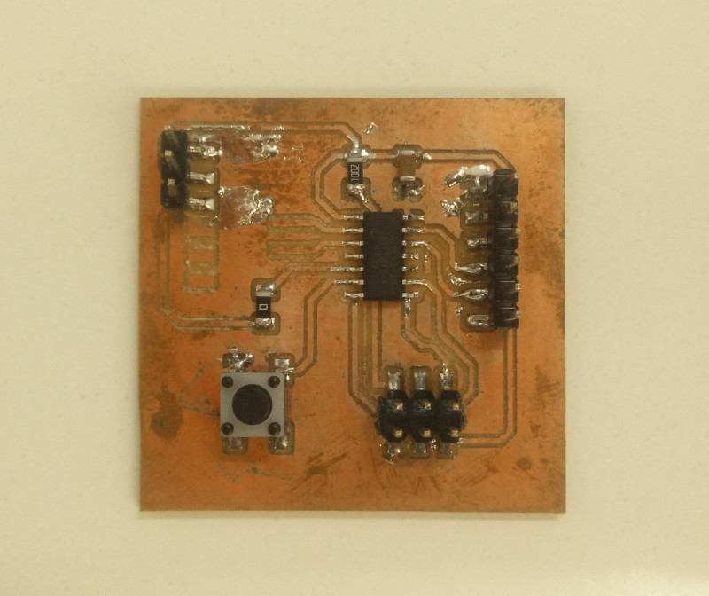
Here's the "Hero Shot" of the actual final servo board result: milled, stuffed with components and programmed (for details see Week 04)
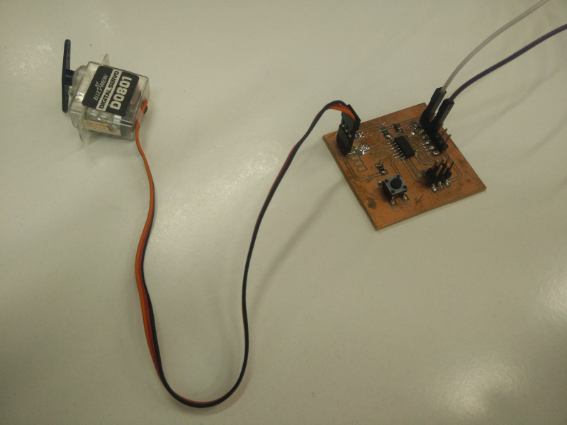
and here with servo actuator attached
Source files
- servo.sch -KiCAD Eeschema output SCH File
- servo.net -KiCAD Eeschema output NET File (Netlist)
- servo.kicad_pcb -KiCAD PcbNew output KICAD_PCB File
- servo-F.Cu.svg -KiCAD PcbNew output SVG File (Traces)
- servo-F.Cu.png -Inkscape output PNG File (Traces)
- servo-F.Cu.rml -Fabmodules output RML File (Traces)
- servo-Edge.Cuts.svg -KiCAD PcbNew output SVG File (Edge)
- servo-Edge.Cuts.png -Inkscape output PNG File (Edge)
- servo-Edge.Cuts.rml -Fabmodules output RML File (Edge)
- servo.ino -Arduino IDE output INO File