Mechanical Design, Machine Design machines that make machines
Digging for ideas design thinking
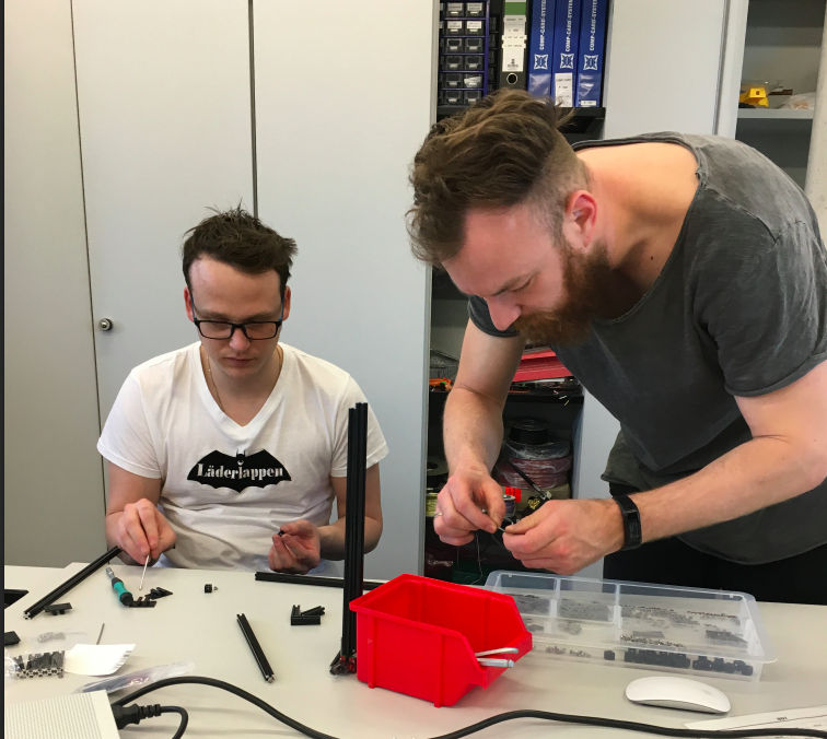
Teamwork work together
The machine we want to build should be build as a group. Please follow the link below if you want to see the rest of our group study.
Tools what we used to fulfill the task
Makerbeam
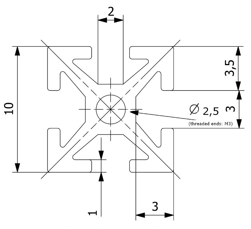
The Makerbeam project deals with the idea to be a easy to use and for its small size stable modeling option. It consists of aluminium profiles that comes in several sizes with a footprint of 1x1cm.
Fusion 360
Fusion 360 is from Autodesk. It's similar with Inventor but it's cloud based. The best advantage that it has in comparison with Inventor is, that it can be installed on my Mac. So I can use it at my Windows workstation at home and on the go on my Macbook.
Makerbeam rapid building structures
Makerbeam is a toolkit of various aluminium profiles that can be easy attached to each other by using specific screws that fit into the profiles. There are also a lot of add-on parts that can be used to build all kind of stuff. For example there a bearings, joining plates in several angles and linear bearings. All together is a very universal toolkit to build all kind of structures, machines and frames for your projects.
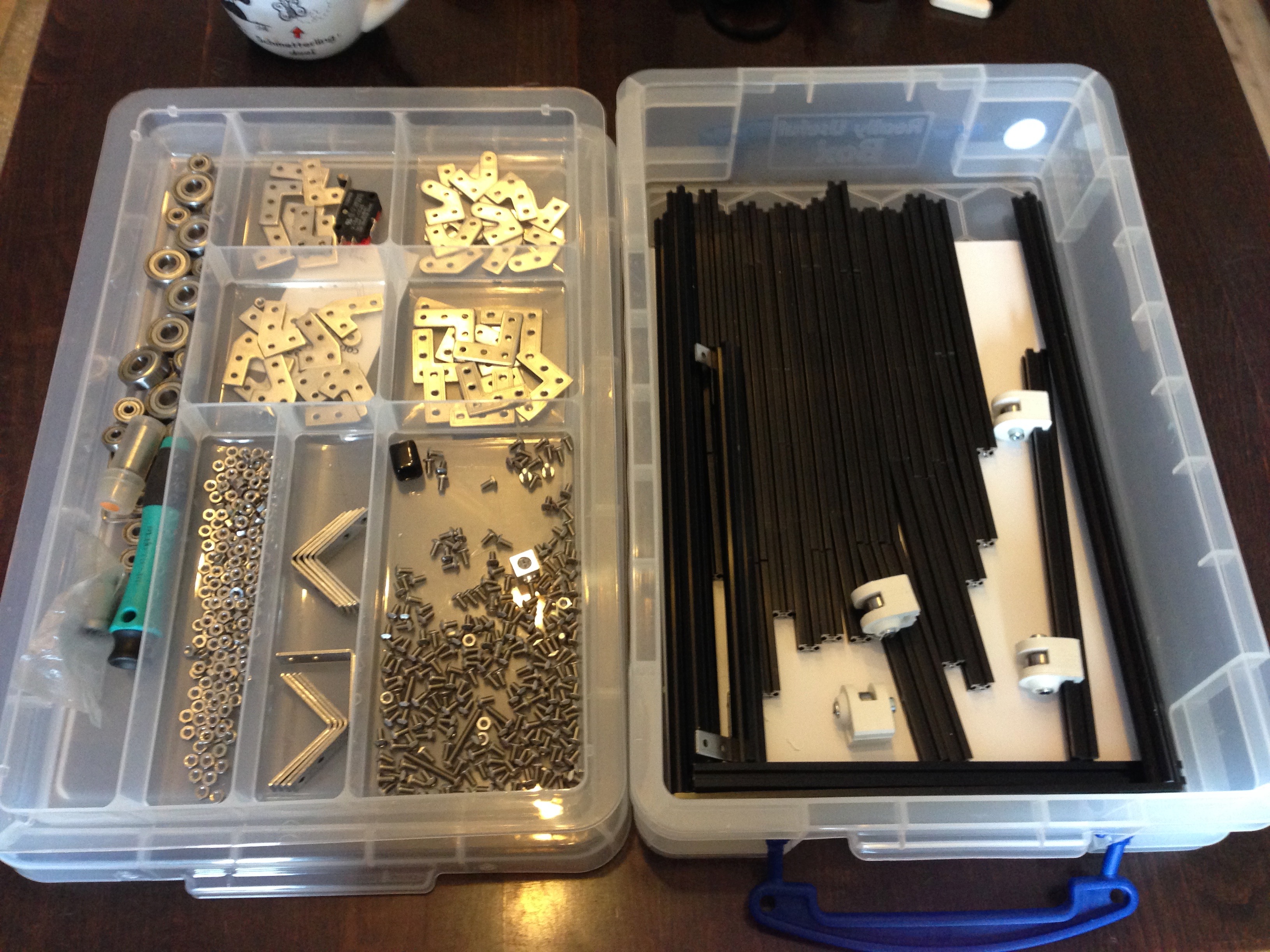
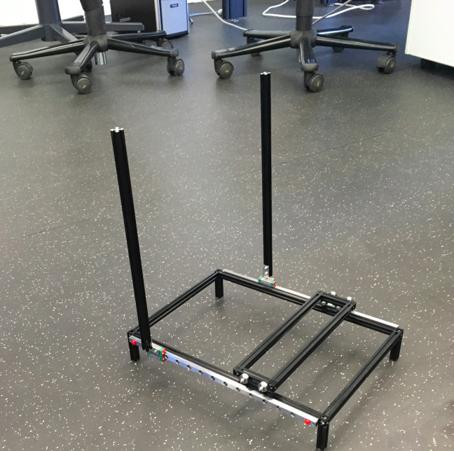
Starting this weeks project we were using the Makerbeam rapid prototyping dev kit. At first we were testing some methods and start a construction to become a feeling about how large the machine will be and what is possible with this kit.
Designing the mounts using Fusion again
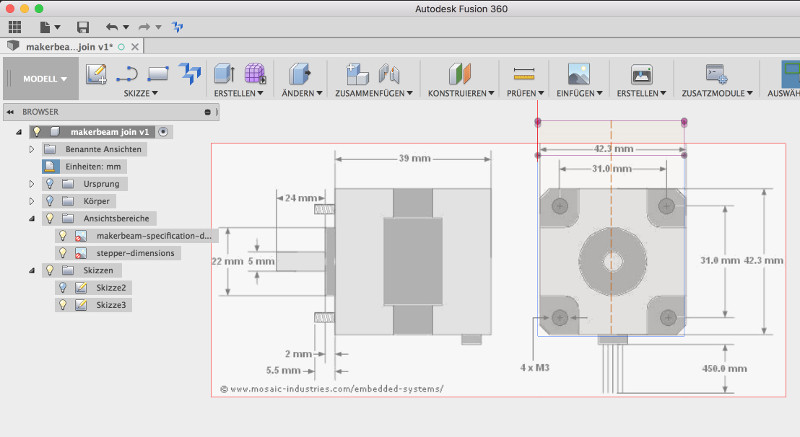
With the frame set up whats left are the mounts for the electronic parts like the brushless motor and and the stepper motors. I used Fusion360 again to design them. First I downloaded the footprint of the Makerbeam and and the Nema17 motors from the internet. After creating a new project I added the image of the Makerbeam footprint to the x/y plane. In the dialog that appear when adding the image I also told fusion to set the opacity of the image to 50% to be able to see through the image and to draw on it easier to the the lines I drew.
When the images is now placed on a plane Fusion add a new entry in the file browser for the construction image. Now whats left is to scale the image to it's real world size. To do so I right click on the image in the file browser and select calibrate. Now I select two positions on the image where I know the exact size of and enter this size in the dialog that appears.
The result is a image in my model where I am able to sketch on. This technique helps in the modeling process to preview the building on the footprint and see if the part is really fitting in the real world.

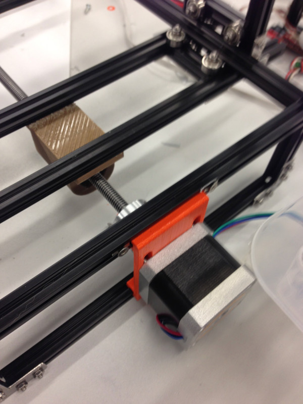
The parts I designed comes in two variants. The first one is a mount with the motor fixed in one position and the second one has larger holes for the screws so that the motor can be moved for 1cm. This is to calibrate the axis to prevent bending of the rod.
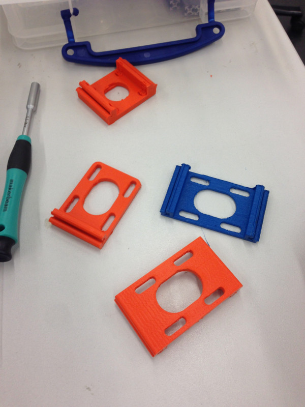
This results in several test prints. The overall problem is, that the tolerance of the printed material was often to hight and even this a modeled tolerance of 0.1mm on the teeth of the mounts. Thats why I had to reprint the model again and again and increase the tolerance of the part until it pressfit into the Makerbeam profile without any space between the mount the the aluminium profile.

Setup the motor Arduino and ESC board
In our project we want to use a brushless motor to drive the mill. Because the motor is controlled by an ESC controller I first want to give the motor a test drive to be sure that it can be handled later in the project.

Below is the test code the initialize the ESC of the brushless motor. I hooked up a Arduino to a potentiometer and a brushless motor.
#include  // include the servo library

Servo servo;  // create servo object

unsigned long starttime;
unsigned long interval = 100000; //Intervall in Mikrosekunden
int val = 25; // Current value

void setup(){
  Serial.begin(115200); // initialize the serial connection for debugging
  starttime = micros(); // remember the start time
  servo.attach(3);  // init the pwm on port 3
  servo.write(25); //Is used to init the ESC
  delay(2000);  // wait the seconds
}

void loop(){
  if ((micros()- starttime) >= interval){
    servo.write(val); // set the value of the motor
    Serial.println(val);
    starttime = micros();
  }
  val = map(analogRead(A0), 0, 1023, 30, 110);
  servo.write(val);
}
The result was that after the initialization I can be control the speed of the motor by the potentiometer. I also opened the serial monitor to plot the current value of the motor speed.
Download section parts I made
At last here are the parts beside the Makerbeam I designed on my own.
| Nema17 Makerbeam mount f3d (Fusion360) | download |
| Nema17 Makerbeam mount stl | download |
| Nema17 Makerbeam mount 1cm versatile f3d (Fusion360) | download |
| Nema17 Makerbeam mount 1cm versatile stl | download |