Computer-Controlled Cutting all about cardboard cutting and vinyl design
This week documentation deals all about the work with our cutters. At first we discover as a team the abilities of the laser cutter and then create a pressfit construction on our own. At last we use our vinyl cutter to create a sticker.
Discover our laser cutter what it can do and what not
Teamwork discover together
This task was a teamwork exercise so we created a documentation site together to describe the abilities of our laser cutter. Please follow the link below if you want to see the rest of our group study.
Engrave images smoke generator
Because we cannot use the windows driver of the epilog laser because we do not have windows machines at the laboratory, we are using the software VisiCut to communicate with our laser-cutter.
We are using a epilog laser-cutter 50W at our FabLab at the Hochschule Ruhr West. Now to import my design to VisiCut I had to add my test images to Inkscape and using the VisiCut plugin to add the images and the additional text under the test image and a frame to cut everything to VisiCut.
We are using the VisiCut to send our designs from our computer to VisiCut. Here is also the place to set the properties for cutting job.
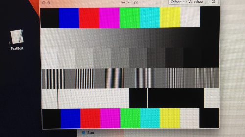
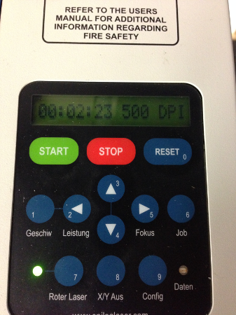
The following images show, that the test image is printed at 500 dpi. The second image show the print process. You can see that every line is burned at once line after line.
As the result of the engrave job you can see the difference between the normal engrave and the 3D engrave job. In the normal engrave the only shades of intensity are an optical, when you have a pattern like black lines that are more or less close together. On the right side you see the 3D engrave. Here the intensity comes when the laser burns deeper into the material. Because you can see this as a greyscale representation of that image. There is no difference in color, only how intensive the color is. The result is a real 3D image. It looks like a translation to braille for images.
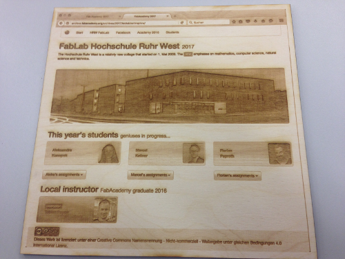
On top I engraved the screenshot of our FabAcademy FabLab site to demonstrate the 3D engrave ability in a real world example. As you can see there is a mix of images text and some gradients.
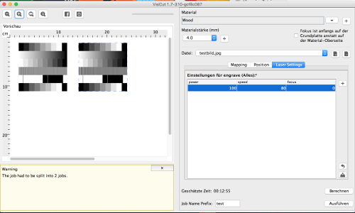
I looked inside the cutter documentation to find out a configuration for my 4mm thick compressed wood. So I chose the following configuration.
| type | power | speed | focus | dpi |
|---|---|---|---|---|
| engrave 3D | 100 | 80 | 0 | 500 |
I made a small video from the engrave process. There is a difference when you have a vector bases job and a raster based one. You can see the difference in the print process where we here look at a raster based engrave job. You can see that the laser cutter is cutting line by line. Have a look at my video about the pressfit construction. You can see that the cutter does a vector based job and moves more on the y axis of the print-area.
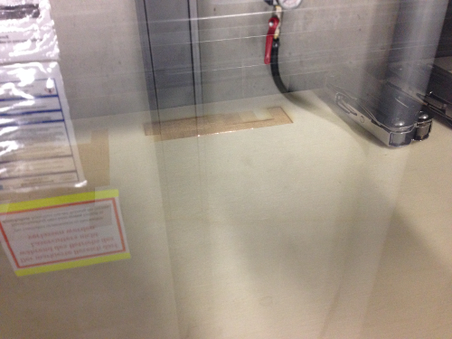
Here you can see the result of the engrave job. When looking at the result from above it looks like a brown grayscale image but from the side you can see how the laser burns at several layers to simulate the the color intensities.

Pressfit construction cut and connect
Here are the sources to the tools I used for my pressfit construction.
Fusion 360
Fusion 360 is from Autodesk. It's similar with Inventor but it's cloud based. The best advantage that it has in comparison with Inventor is, that it can be installed on my Mac. So I can use it at my Windows workstation at home and on the go on my Macbook.
VisiCut
This is a user-friendly tool for laser cutting and it is available for OS X. It supports SVG, EPS, DXF and the VisiCut PLF (Portable Laser Format) and send the print jobs to the laser-cutter.
Starting this weeks solo parts of the assignment, there is a model for cutting that has to be done. Instead of using a 2D vector graphic tool I create my model with Fusion360. The positive about this solution is that I am not only be able to model the pressfit parts on their own, I was also able to join several parts together and see how the parts fit together.
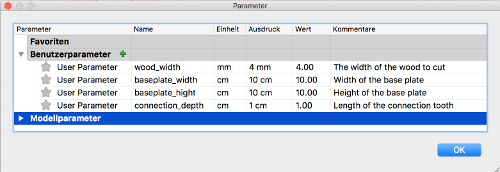
Starting again with a Fusion model I come to the point that it is best practise to set up the model parameters at first as far as you know with parameters are important for your model. Because I will focus on joining parts together I thought that it is a good idea to parameterize the connection part and more important the thickness of the material. This is important because different material sizes results in different connection distances.
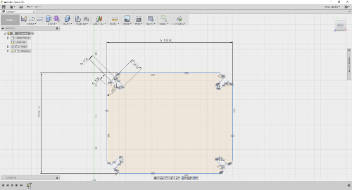
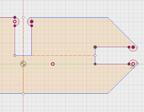
With the parameters set up I created the sketches for different parts that later should fit together. As you can see in the images the part are completely set up using the parameterized dimensions I mentioned before.
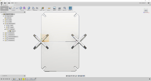
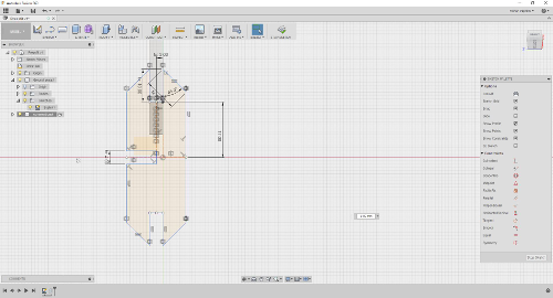
To add more possibilities to construct the model I alter the connection parts to some other versions. Here I rotate one side of it to create a curve element from it.

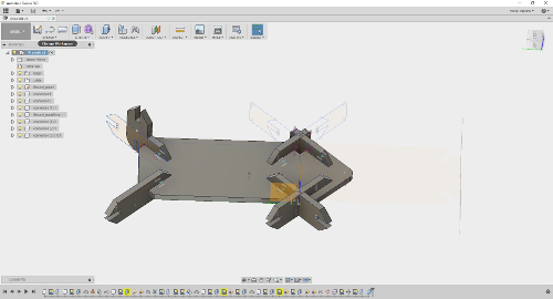
With all the different versions of the connection parts and also an iteration of the base plate, I joined all together to demonstrate in Fusion how the model could look if connected.
Before cutting the model I had to export all the parts to a format our laser cutter or the VisuCut sender is able to understand. Fusion360 is able to do that. It can export sketches as DXF files. What is left to do is to create a sketch for every face of the model that you want to cut. With the sketch created you can left click on the sketch in the browser and choose 'export as DXF'. This DXF files can be understood from VisiCut and we can go on cutting the parts.
Send the model to the cutter time to laser stuff
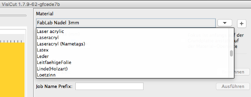
After the model was finished I was ready to cut the model. I fired up VisiCut and added a new material to the defaults because I see no matching material in the drop down list. So I added the cardboard material and also two available thicknesses I found. Beside of some cosmetic parameters like the color, there was not much to do. When I came back to the main interface view, I imported the main board of my pressfit design and place it onto the cutting area.

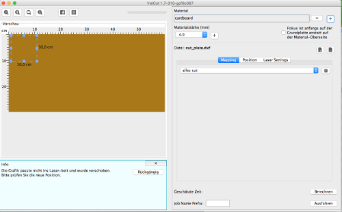
I selected 'cut all' as type for my cut job because I don't want to engrave anything here and switched to the cutting configuration view. Initially it started with the configuration the printer manual gave me but was not sure if it is correct for the type of cardboard I used. So I'll give it a try.
| type | power | speed | focus | dpi |
|---|---|---|---|---|
| cut | 20 | 100 | 0 | 2500 |
As expected, after trying the first configuration of it was resulting in not cutting all the was through the material.

I try to double the power for the next try. Because 20% was not very high and I used a relative strong cardboard I found in the garbage.
| type | power | speed | focus | dpi |
|---|---|---|---|---|
| cut | 40 | 100 | 0 | 2500 |
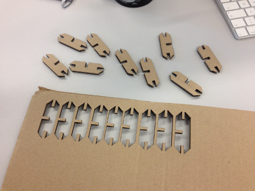
This configuration seem to work very good for my 4.1mm thick and relative strong cardboard. There were no flames during the cutting process so I saved the configuration for later in my VisiCut preferences. Now I had a reasonable configuration I want to cut all of me designed models. See the result in the images below.

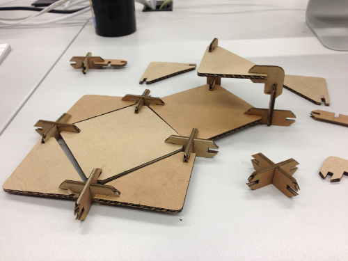

So far so good. The different part assembled very well and fit together almost good without falling apart. But I would have a better feeling if the parts would have a stronger connection even with a flimsy material like cardboard. So I gave my model a redesign and added some teeth at the end of the connections. Also a placeholder whole where they rest when assembled. To do this I first added the round teeth at the end and mirror it on all the necessary edges. After this a projected the teeth where they stick into the other part onto a new surface on the counterpart. With this marks I was able to make a whole on the right position.


This was my final design for the assignment. With these changes the parts fit better together as before. This method is a good practice for cardboard but would create some problems if I would use a stiffer material like wood. If I had to take wood, I would design the teeth way smaller. Maybe it is a good idea in the future to parameterize the size and amount of teeth also.
Here is a video about the cutting process.
Feel free to try it for yourself. I added all the generated files below.
Download section try yourself
| Pressfit model f3d (Fusion360) | download |
| Pressfit model STEP | download |
| Pressfit ready to plot dxf archive | download |
Vinyl cutting make a sticker by myself
Putting a lot of time into the pressfit construction and the research on our laser cutter, I want to work on the vinyl cutter very straight forward. First I searched on the internet for a logo of the type of my car. This is a VW Scirocco. The logo of it has a specific font so I searched for it and found a JPEG file.
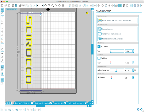
This image I added to the software of our vinyl cutter. It comes with its own nice software named Silhouette Studio
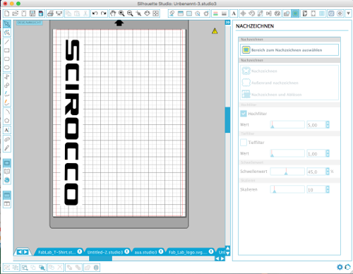

Silhouette Studio is pretty straight forward. After adding the logo image via drag and drop into the the editor, I had to arrange it so that it fit onto the Din A4 sheet of sticky vinyl.
Similar to the Inkscape tool where bitmaps can be converted to vector paths also die Silhouette software has such a tool there it create a threshold of the image and then try to analyze the the border of the objects in the image and create a path on it. Because a vinyl cutter is not able to handle areas like the laser cutter when it engrave an object the cutter is only able to cut paths into the sheet. So it detects the outer shape. To detect it there are some sliders where you are able to fine tune the threshold value and the filter where it borders are recognized.

After this process the shape is ready to cut. But it depends heavy on the kind of material that should be cut. The printer software has a lot of pre defined materials. After selecting a matching one the software asked you for manipulate the blades depth to cut all though the vinyl layer of the sheet. When a plotted sheet is cut to deep on not through the vinyl layer you can adjust the blades depth again and update your plot profile for that material in the software.

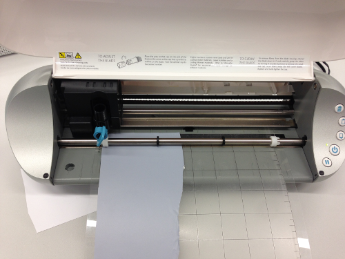
Here you can see the vinyl cutting in progress. I used a rest peace of vinyl that should match the size of my model in my opinion and put it in the sticke cutting underground with goes through the cutter during plotting process too. Because the plotter only has to cut out all the silhouettes of a model, the cutting process is very fast.
Download section try yourself
| Scirocco logo (studio3) | download |
SVG import Working with vector graphics
The most simple way to work with cutting tools is to use .svg graphics at first. Because of their nature svg is not a pixel by pixel description of an image, it is more a description how to draw a image. Inside a svg there are things like draw line from x/y to x/y and draw a circle with the center at x/y and with the radius x. The downside is that not every image can be described that way. Mostly images that are shapes in some kind of way can be described by svg.
Now that we describe how svg works you can imagine that is easy for a x/y axis machine to follow the shaped that are describes in the svg image. So when shape is a line from startx 10/20 endx 20/20 a machine like the lasercutter can send the same coordinates to the movement motors that cut the line with its laser.
Lets's take the FabLab logo from wikipedia FabLabImage and import it into visicut.

As you can see when importing a svg file and config visicut to cut everything it recognize the silhouette of the svg image and is able to cut is directly.
Download section try yourself
| FabLab logo (svg) | download |
| FabLab logo ready to cut (visicut) | download |