Microcontrollers come blank with no information as to what the chip should do. When we create a new board we need to flash basic information onto it so we can access it from a computer, this includes even being able to be accesed via USB. The FabISP (Fab in system programmer) allows us to program blank AVR microcontrollers with this basic information.
This weeks task involves creating a FabISP from it's componenet parts. Milling the boards, selecting and soldering the components and finally flshing the board with the basic info we need to use it via the 6-pin ISP header.
I finally made the effort to start using another program to personalise the board. On Inkscape, I removed the cba logo and populated my board with a memphis inspired pattern.
I stuggled with this so had a go with photoshop instead. The work flow is as follows:
we milled the board using a Roland SRM-20 machine. We first had to clean the mounting board to ensure it was as flat as possible. There was some double sided tape residue left over from the previous person and when cutting to a depth of 0.1mm this can make a big difference to the cut.

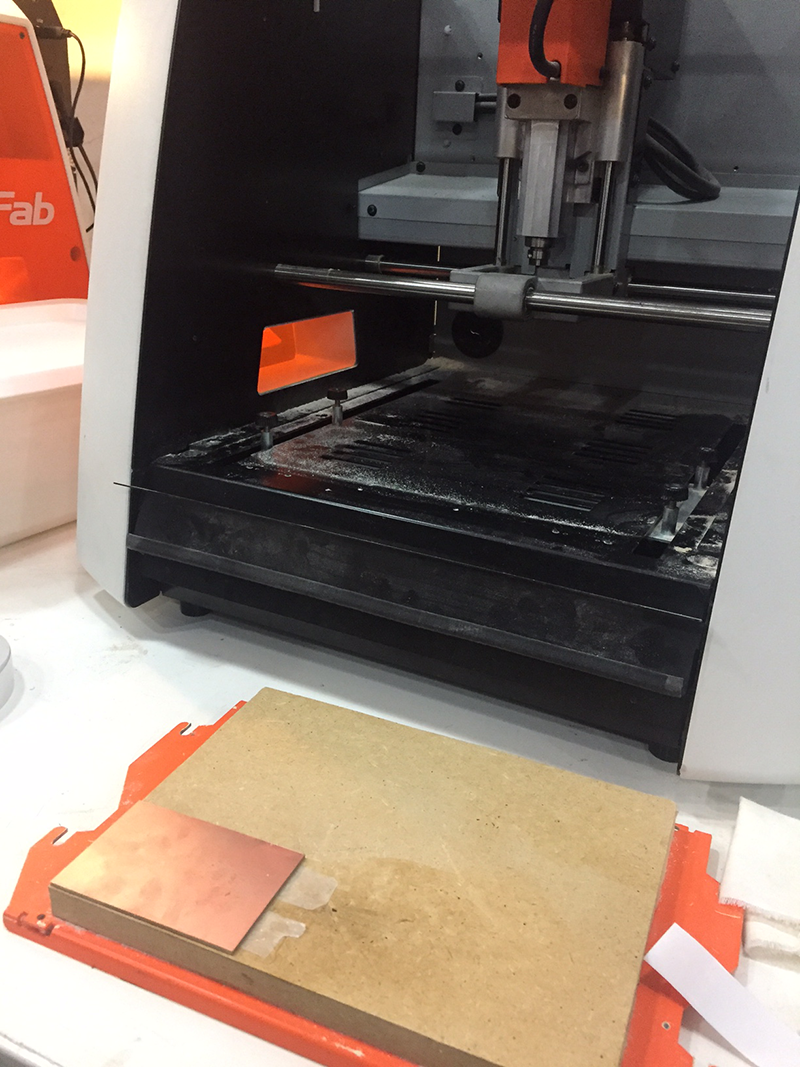
Once the mounting board is clean using a mixtue of physical and chemical (isoporpyl alcohol) force, the blank board is attahed using plenty of double sided tape to ensure it is secure.
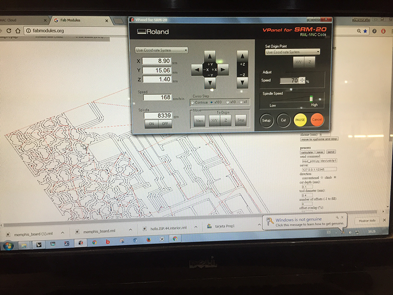
We created the gcode for the miller using a web interface called fabmodules. FabModules uses png files to create the code and it cuts the black area and leaves the white. It is very easy to use and you can even 'invert the image' at this stage incase you forgot the final step in photo shop. The two files I created earlier were used first for the interior of the board using the 1/64" bit to cut the traces and then the exterior using the larger 1/32" bit. It is possible to set the offest of the milling (aka how far clear the traces are with -1 completely clearing the board and 1+ indicating how many passes the bit goes from the black/white intersection. We went with 4 as this gave a good edge and clear traces for easier soldering, but we didnt have to wait for all the unused copper to be removed. Once we had zeroed the machine using the 1/64" bit we could send over the gcode and begin cutting.


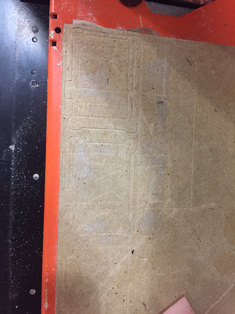
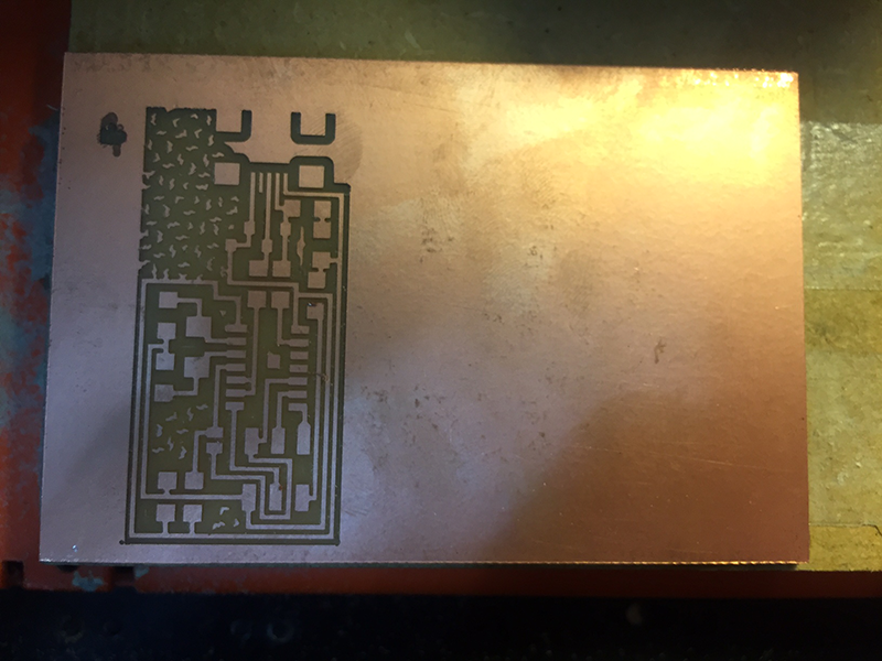
It is a good idea to start with the bit moving slowly across the piece and check the initial cut. My first cut (on the left) did not go so well. It turned out the drill bit had been broken and was just chewing up the copper. With a new bit my piece looked much better ad really showed my Memphis pattern.
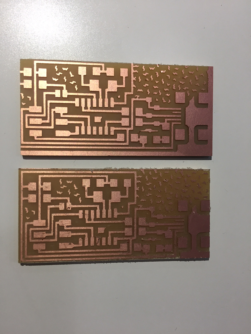
After the initial detail is cut we swap over to a 1/32" bit to mill the outside and release the board. For some reason I had some scaling issues when using inkscape to create my memphis board which meant the xy zero was in a different position. This meant I had to do it again, but at least I had a piece to test soldering out on.

- ATtiny44 Microcontroller : A great microcontroller for running simple programs. Small, cheap and easy to use.
- Capacitor : This component stores energy, coomonly used in circuits for local energy storage, voltage spike supression and complex signal filtering. In this circuit they .......
- Resistor : Adds electrical resistance to a circuit.
- 'Jumpers' 0 ohm resistors : The jumper allows us to complete our circuit in places where the circuit crosses. This creates our '2.5 D' circuit
- 6-pin Header : To program the microcontroller with the initial information.
- USB Connector : To program the FabISP once flashed with the basic info
- Crystal 20MHz : An electronic oscillator circuit that uses a piezoelectric resonator. This provides a clock input into our microcontroller
- Zener Diode : Allows current to flow in the opposite direction when the diodes "Zener voltage" is reached. Semiconductor diodes normally have zero resistance in one direction and very high resistance in the other.
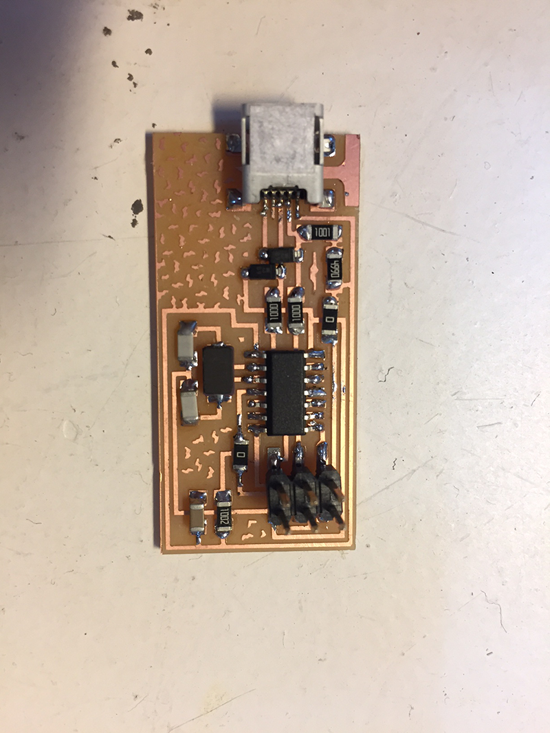
The soldering was tough, but satisfying. I was succesful on my first attempt, but I certainly need more practice, especially on the smaller pins. We used a solder iron set to 350 and I found the magnifying lights incredibly helpful.
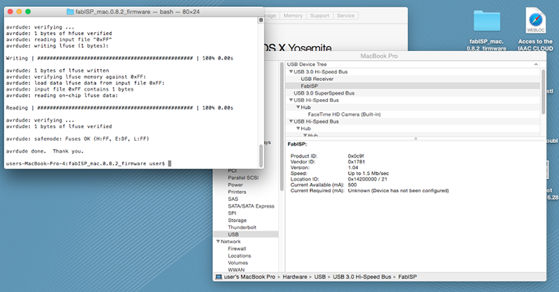
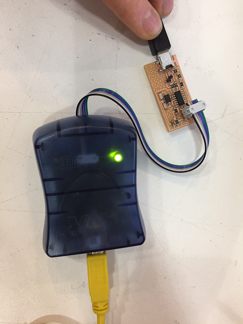
Once complete we did a 'smoke test' which involved simply plugging into my computer to test for an error (this would suggest a short circuit). Mine was OK/not OK, the computer kept changing its mind so I decided to try my luck and go onto the programming step.
programming walkthroughThe first attempt was not succesful, but so I went back a resoldered some of my joints. The smoke test was flawless and the programming was a success.