The aim was to explore push fit construction and also to build a parametric model.
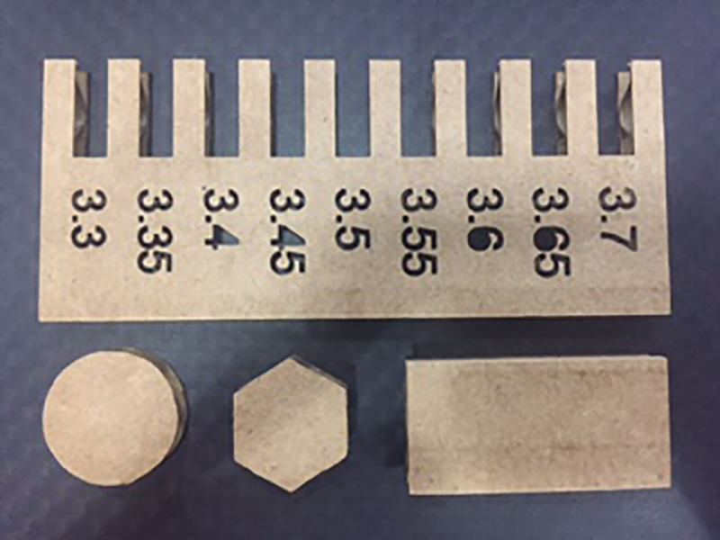
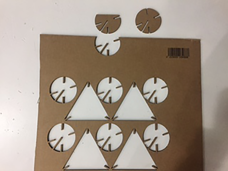
The first task involved creating a test piece to see how big a hole we need to greate a push fit joint. We were intially using card which has a bit of give so it was not easy to accuratley measure the thickness.
I created a parametric grasshopper file to create the test piece. It is possible to alter the piece for the thickness of material, the range to test and the increments to test beetween. This will be useful for furture projects when I am using different material. The file can be downloaded at the bottom of this page. The material was approximately 3.5mm thick so I did a range of widths ranging from 3.3 to 3.7 at 0.05mm increments.
I also need to take into account the kerf of the laser. Again using card this is quite difficult with the flexibility of the material, but when I move on to ply or acrylic this should be easier.
Having said this I do like the freedom of carboard as an available and cheap material and also the speed in which iterations can be tried out using both this material and the laser cutter together. In the end I went with 3.4mm for my pushfittings. This allowed a tight fit between the pieces so the model did not fall apart.
Fortunately the laser cutters we had available all used Rhino and its 'Print' as the interface, so I could use my Rhino files. It was important to ensure the scale and work area of the pieces were set, which could all be done in the Print window by going to 'View and Output Scale' --> 'window' --> 'set'. This allowed us to also set the zero of the laser. We had a few laser cutters available. I used the Trotec and the feeds and speeds for the different machines and materials can be found here.
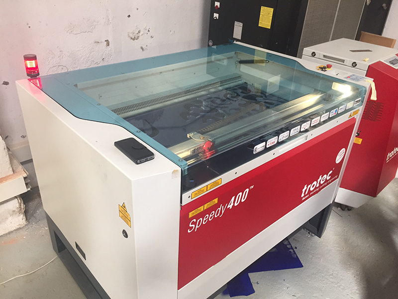
Even with having the feeds and speeds for the different machines, testing is necessary. This is due to many factors that may cause the laser to be working less than 100%. For instance if the bed isn't level the laser is not always optimally focused. The main reason I found was from a dirty mirror in the machine, this meant the laser was less powerful. This was often due to innapropriate materials or innapropriate settings for the .project which led to a lot of smoke being produced.
After doing a few test cuts I went with:
To cut:
speed - 15%
Power - 100%
To engrave:
speed - 90%
Power - 10%
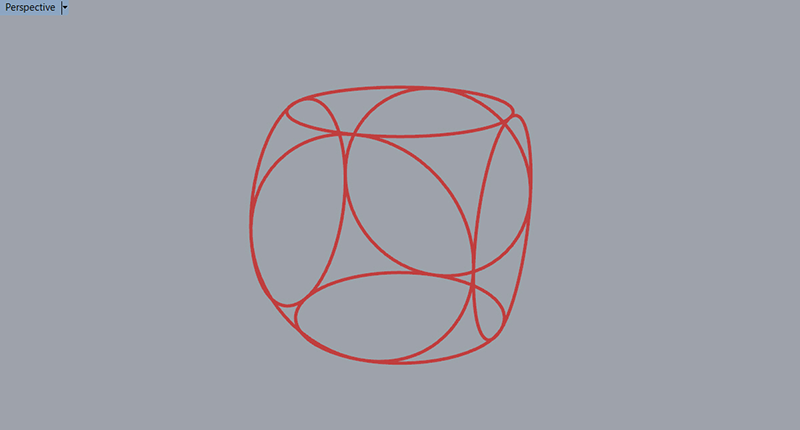
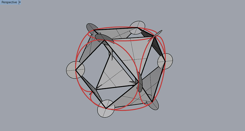
I discovered a geometry while playing around in rhino which ended up being a Cuboctahedron.
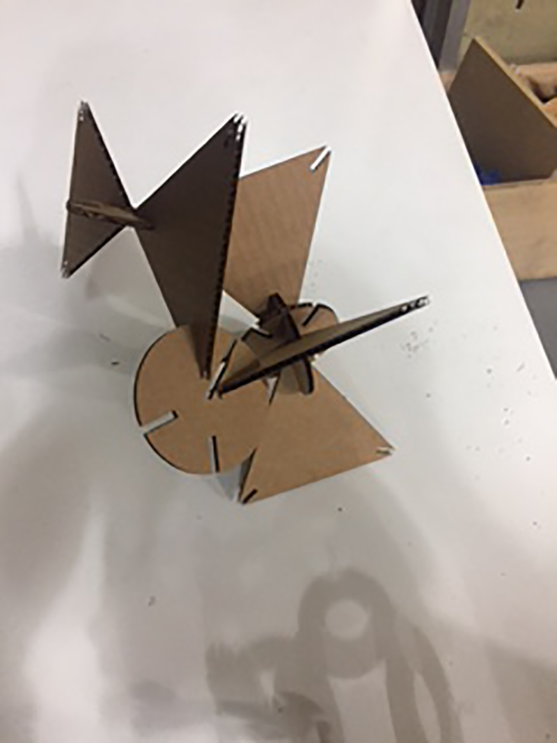
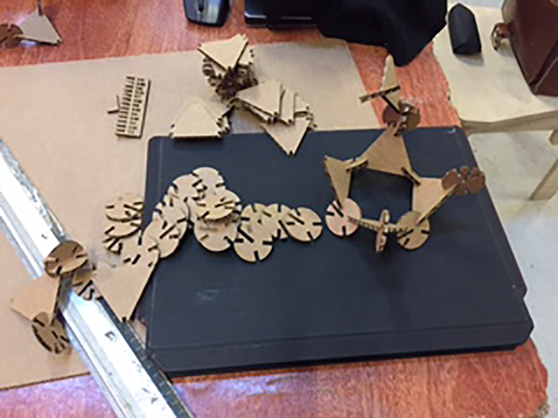
I rushed my first attempt which ended up relatively succesful however there are definitely some improvements to be made:
- increase the size of the pushfit gaps.
- add chamfers to the outside corners of the pushfit gaps.
- decrease the length of the slots to avoid overlaps.
- decrease the size of the pieces (to create more pieces in one cutting session and waste less material.
- make sure my cutting file fits on the piece to be cut! ('cubo3')
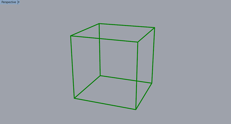
I created a parametric file for the shapes. This allowed me to change the radius of the shapes with the push fit holes altering in size as well. I was also able to change the width of the push fit gaps to match the material thicknes. I included fillets on the outside edge of my push fit holes which helps to align and allows entry between the pieces.
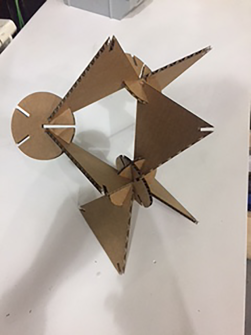
I like how this shape fits together and it could make a very interesting modular shelving system. (after a lot of adjustmant) with alternating modules containing different inputs/outputs and all the the pieces connecting together and transfreing power and information.
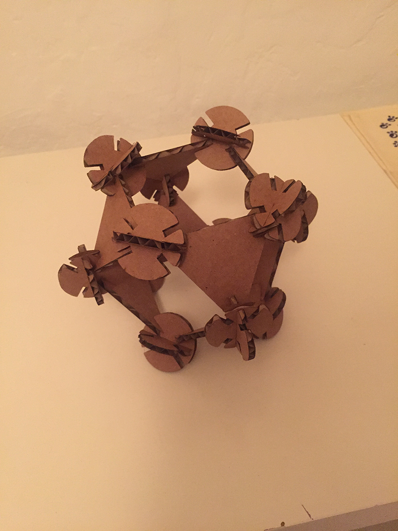
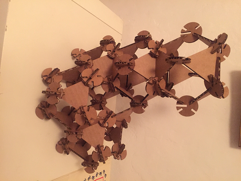
With this card prototype I had a few issues and it was mainly due to the material and the scale. The scale made connecting the pieces fidly and although the logic of my parametric model ensured no overlapping of pieces, it was effectivley touching and all a bit cosy. The material was a bit flexible and easily damaged. Although springy and good for push fit, once damaged the joints were not always so good. I would like to play with this geometry further with different materials and scales to see what I can come up with. Also different ways of attachment such as spring fit using wood etc.
Kerfing Around
Having access to the laser cutter I wanted to have a play around with kerfs and how a varying effect of the pattern on a single piece will have a variable effect on the curvature. aka Define the curvature and then apply a pattern so when compresed it forms a specific pattern.
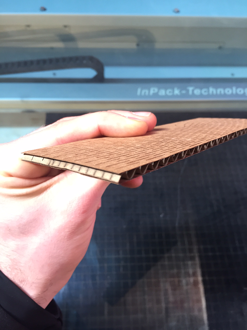
It is amazing to have a piece of rigid material turn into something so flexible and with some patterns even have double curvature.
Some installations and experiments which have inspired me in the past.
- Wooden Waves at Burro Hapold Engineering by Arthur Mamou-Mani
- This Instructable by Aaron Porterfield
I did some intial experiments using some of the patterns downloaded from the instructable. I was a little dissapointed with the flexibility of these experiments, but then realised I did not take into account the direction of the corrugation. A colleague did similar patterns in card across the direction of the card with much better results.
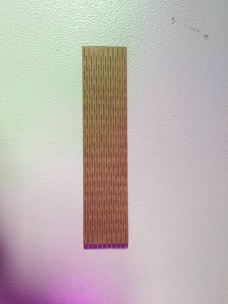
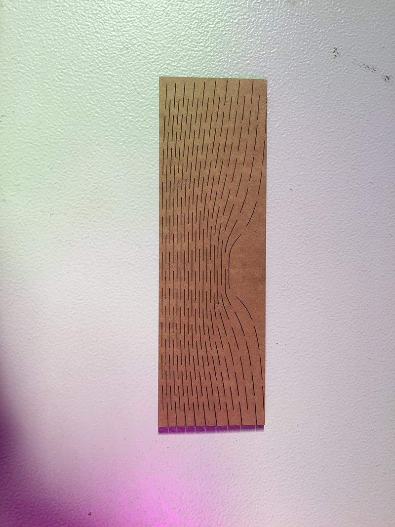
I played around with the orientation with the pattern in grasshopper using attractor points. I did a small test on a thin (~2mm) piece of ply with interesting results. Of course I had to test the flexibility/rigidity hence the two seperate parts
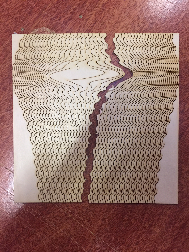
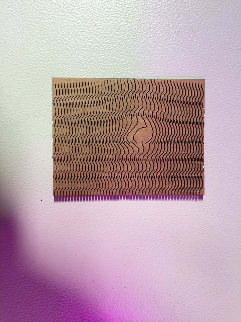
I did find that the curvature did change and I want to have a play with the pattern further. I would perhaps do various, more linear but different spaced patterns and measure the maximum radius. Then in grasshopper I could create a surface, analyse the radius at specific poits and apply the pattern density to achieve this.
Further experiments - kerf cardboard (take off just half of material - vary width of hole). raster on cardboard. kerf to allow angular beding (3d bending)
ivy plugin for grasshopper algorhythmic sculpture/chair/light fitting/plant holder - natural growth etc. kerf experimentVinyl Cutter
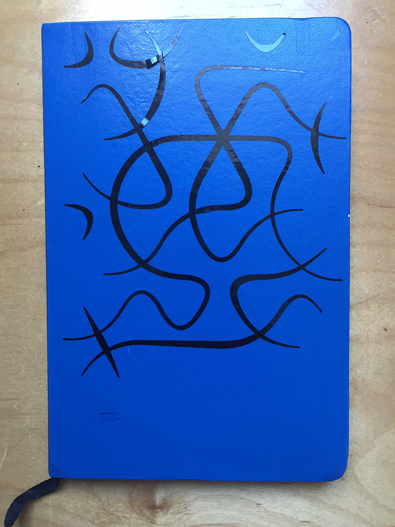
Using Grasshopper, I created a file that connected each of the 2 sides of a hexagon. As hexagons are infinitely tileable this creates a series of curves that creates a pattern with non having 'loose ends' except for the edges. A bit of randomness included as well as some variable pipe and I ended up with this pattern. I took the curves and saved them as DXF file types so they could be read by the vinyl cutter.
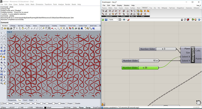
I initialy scaled it to fit on my computer, but after seing colleages attempts with small intricate designs I scaled it up slightly to fit on my Spanish workbook. We used the Roland GX-24 vinyl cutter for this which is a remarcably effective machine. Once cut we remove the bits we dont want and apply blue backing paper to lift the design of the initial backing. I can then transfer the design onto my book.
I definitely still struggled with this design, with bits not coming off easily. My Spanish workbook had a slighlty glossy finish. This made it hard for the design to stick down and so remove the blue backing. I managed in the end, but in future I will make sure I use a better surface.