So I felt very fortunate this week, I had been working on the nRF24l01 radio transmitter and reciever for my remote cotrol robot and Neil mentioned it could be used in the assignment this week. I fortunately got all this working on the arduino before hand so now it was to combine my output/input/networking week into one board. For the NRF24L01 radio transceiver I will be using this tutoial.
I was succesful using this tutorial with the arduino. I recieved some help from Citlali who pointed me towards the tutorial anD helped troubleshoot.I did struggle at first as I have not used Eagle since the embedded programming week, so I was reintroduced to all its quirks as well as getting the file ready for milling.
I didn't really go off any scheme, just kind of what made sense to see how I got on.
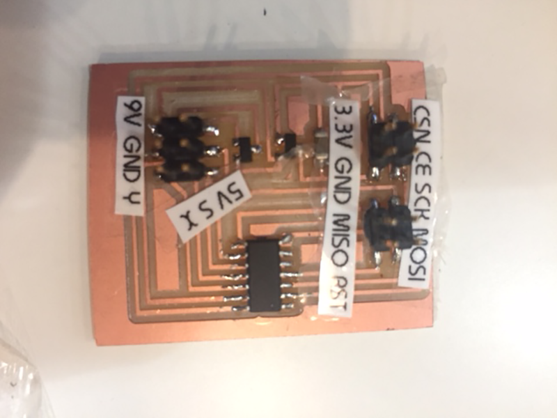
I started with the transmitter. I didtched the FTDI cable as I was providing the external power and only had one set of MOSI/MISO/SCK/RST/V/GND for both the radio unit and the programmer. This is because both use SPI communication.
Not having the FTDI cable meant I could not communicate with the computer, which I did not see as a massive issue as I could check it was working using the reciever hooked up to an arduino.
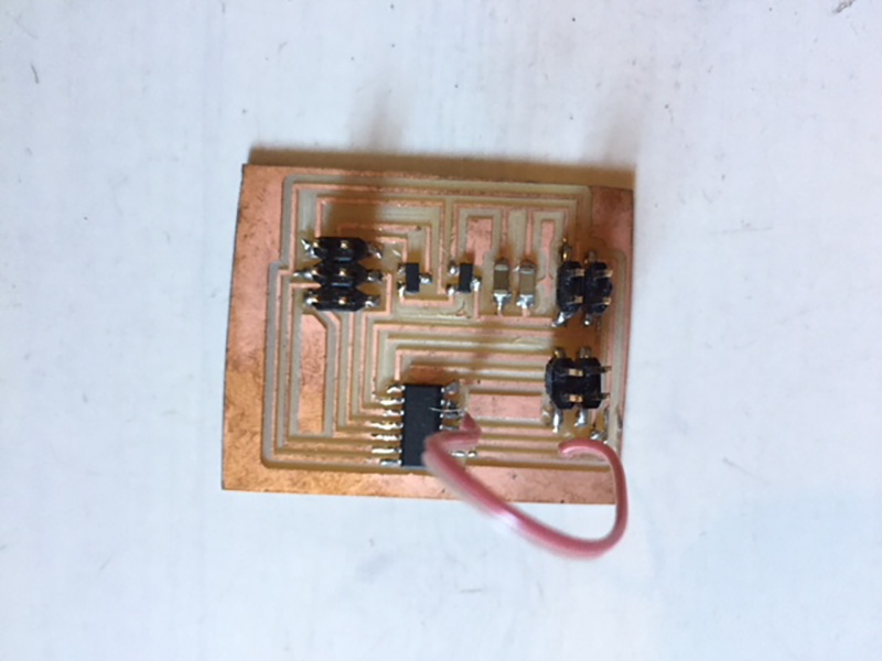
My MOSI/MISO etc.. setup did work, after much umming and ahing, and I was able to burn the bootloader onto the board, but due to the layout it meant usig jumpers from the programmer which although entirely possible, was time consuming and frustrating.
So far so good. The board should work, I have a tested and working code ready to load. Unfortunately not. The next series of events was a day down the rabbit whole with new issues arising at every turn before I had even sorted out the previous one.
It all starts when compiling the code for an ATtiny24/44/84 instead of an arduino.
Serial - the ATtiny doesnt like the Serial command. Apparently a different library is required, That is fine as I cannot use serial communication with this board as I am missing the FTDI link to the computer. so // commented out. Apparently this may also be an issue with the cores used perhaps. http://jeelabs.net/boards/6/topics/307
Another compile and another error message. I may need different SPI and NRF librarys. This means that my NRF code is not longer valid. I dont fully understand it yet and I did not manage to find a suitable tutorial for replacement code.
I had a nice tuft of hair left on my head which was quickly ripped out when I ran into issues with the architecture of the board. The MOSI/MISO on the ATtiny are effectivley switched round when not being used to program. The SS (save select) aka the CSN connection on the NRF was apparently on pin 6.
Due to this combination of complications, my level of knowledge, lack of being able to error check on a computer (an LED would be nice too, just to confirm power) and a day of not getting anywhere. I have decided to leave this board. I was at the limit of the ATtiny 8k byte memory any way and as this will end up being part of a final project, I imagine I will need more memory so I am going to investigate The following boards:
I have been told these all accept standard arduino code which is great for prototyping on an arduino and bread board and then moving straight over to my own board.
I have decided to go with the smaller 16U2 for the time being as it has enough memory, a direct USB connection (instead of via FTDI) and plenty of pins. I would also need a smaller drill bit for the 328, which is a hassle to use as it is so fragile. If I need more pins or memory I will head on up to the 32U4 mainly due to the time to produce a board with the larger 1/64bit.
I designed two boards one transmit and recieve and got them milled on the Roland SRM20. I am getting much more familiar with Eagle and preparing the board ready for production with a bit of help from my colleagues.
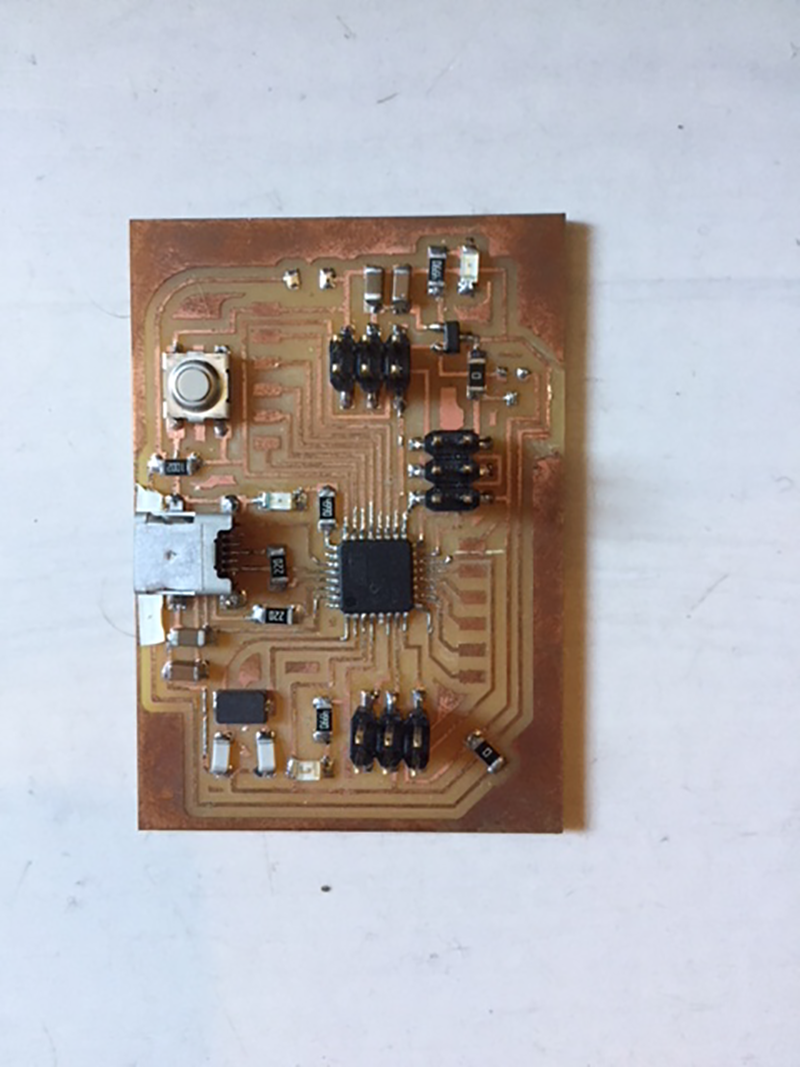
I definitely learnt many improvements from the last board. I have 6 pins that respected the AVRMKII layout so it was much easier to program (I actually messed up a bit with these and placed them backwards by accident). I added a couple of LEDs to indicate power and also hooked up a pin to an LED which I will use to confirm tansmission. I included more resistors where they were required and the micro USB connection which can be used to program and power and also send serial information back to the computer.
For this transmit board size is not so important so Included as many breakout pins as possible so I can potenitally use it to prototype later.
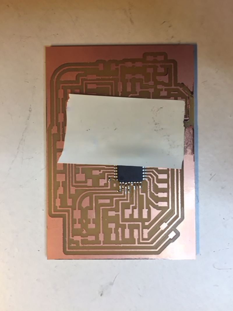
The soldering of the m16u2 chip went well on the transmit, but I messed up a few traces and pins on the reciever, so that will have to be milled again. It is time I got familiar with flux and/or solder paste I think, as I have been told it makes projects like this much neater, faster and more accurate. A bit of tape goes a long way in getting some initial pins soldered to hold the chip in place
I managed to achieve a green light on the AVRMKII meaning my board should be all set for programming. I am not sure which board to 'burn bootloader' in arduino IDE, although succesful, all the boards I had been told had worked were expecting the m32u4 (double pins, double memory). I didnt manage to get to the stage where I programed it with my code succesfully as I found out I was missing a few necessary circuits on the board.
The first one was the crystal. There is an internal clock, but it appears this is hard to access, especially at the programming stage. for this I botched a clock circuit using my breakout pins with a 16MHz clock and two 22pF capacitors.
I found out I needed 22ohm resistors on each of the USB 'D-' and 'D+' pins.
I also needed to add decent power on and reset circuitry.
I found I was able to program via the USB directly so I am going to have a look at LUFA (Lightweight USB framework for AVR’s)(Look for version 100807). When I tried hooking up the LED I had power issues coming up indicating a short. With all the missing circuitry it is time to mill a more complete board. This is as far as I got this week so I will have to continue next week. I certainly learnt a lot more about electronics.
The saga continues...
So I managed to finally get the computer to recognise the chip after firstly stopping the short circuit of the USB connections using some electical tape under the header (many paths were grounded) and also replacing the USB header. I had used this particular ona few times and it appears some of the internal plastics had melted with the repeated use of the heat gun.
While I succeeded in this and learning a lot about circuits and arduino architecture, I quickly came to the conclusion that this was not a viable option. I managed to get the computer to think I was talking to an UNO, but that is only because the UNO uses a 16u2 chip as the USB interface between the atmega368 chip and the computer.
I have also found out a good tutorial using the arduino pro mini 3.3v (basically a mini uno). There is also some good documentation on making an UNO like board from Daniele Ingrasia last year, the Satasha board. Combining what I have learnt with previous builds, the crcutry for the Pro mini and the satasha kit, I am going to put together this board.
SUCCESS!
I am able to program this board as described in the documentation on the satsha using an arduino uno to both burn bootloader and also 'upload via programmer'
After succesfully managing to get an LED to blink (massive success after all the failure), I uploaded my 'transmit' arduino script and managed to send the joystick input via NRF radio to a reciever.
Next task is to get the DW1000 to work.
For programming 16mu2 http://fab.cba.mit.edu/classes/863.14/people/andrew_mao/week11/ programming the 16mu2 using arduino ide http://www.instructables.com/id/Programming-ATmega16A-using-arduino-IDE/ https://github.com/mcudude/MightyCore http://www.pic-control.com/loading-arduino-bootloader-to-brand-new-atmel-microcontroller/ sack that building an arduino pro mini https://www.rcgroups.com/forums/showthread.php?1446159-Making-your-own-Pro-Mini-Arduino if just using 328 (not p) http://fabacademy.org/archives/2013/students/anderson.douglas/atmega328.html http://archive.fabacademy.org/archives/2016/doc/projects/satshakit/satshakit.html