Assignment
-
MECHANICAL DESIGN (week 1 of 2)
-
Make a machine, including the end effector, build the passive parts and operate it manually.
-
MACHINE DESIGN (week 2 of 2)
-
Automate your machine. Document the group project and your individual contribution.
We will attempt to prototype a linear axis machine based on a chamfer rail, rack and pinion mechanism with the aim of making both multi-purpose and modular system.
We base our initial inspiration on Jens Dyvik's fabricatable machines for the simple reason that we can prototype this with the available fab lab machines, namely the laser cutter, 3D printer and mill to make our parts. The goal is to design a simple axis machine without fancy techniques. Here is the motivation and thought behind making our own machines.
Our goal is really to experiment on a rack and pinion rail system that can be easily assembled and scaled in a modular fashion. Despite us all being relatively new to machine building, we will attempt to keep it simple. Some inspiration videos Jens’s ultra DIY CNC machine in operation both for cutting and PCB milling:
My part of the project has been to collaborate in each of the processes of construction and development of electronics.
My first task was to collaborate with julia in the test tests to see if the rails that has been redesigned would work correctly, for this purpose we use as plywood material.

Once the design of the rails has been adjusted, we decided to make a more detailed design test, in this case we created the rails using transparent 8mm methacrylate, for the supports where the x axis is slid, we have printed some 3D parts, which have created Marc and Nico.

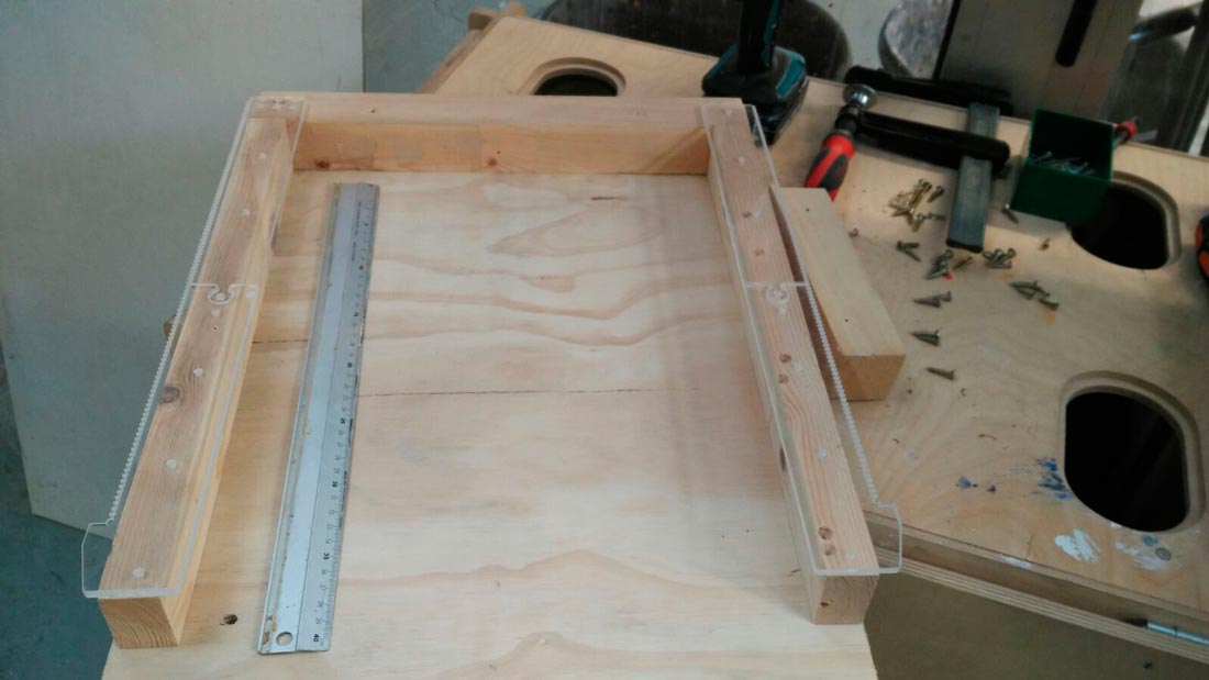
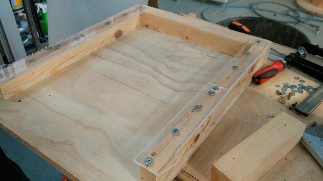
We created a platform in wood and used a few slats to support the methacrylate rails, we tried to make everything as close as possible, since all pieces of wood were not cut with a cnc, this work took Marc and me a lot of time.
We used several screws to fasten the rails to the woods, once all this set, we decided to add a couple of mortores with their respective gears to prove how it worked as we expected.
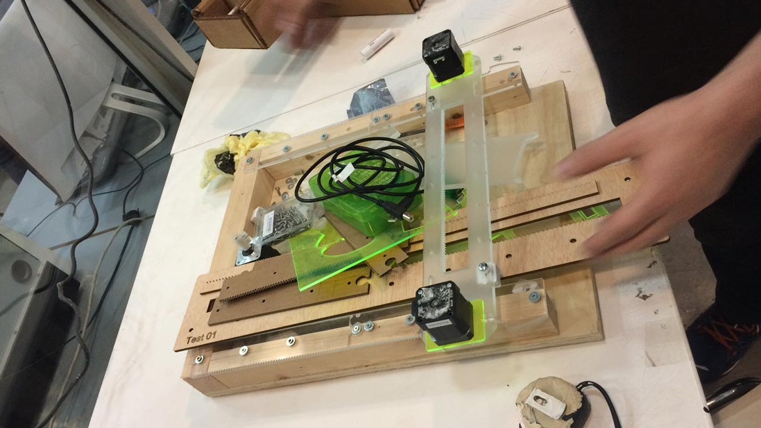
Already mounted everything we did some tests moving the X axis with the hand, we have encountered the problem that it was not fully aligned, besides that it is not very accurate to do this type of tests with our hands, our next step is to make the motors work.
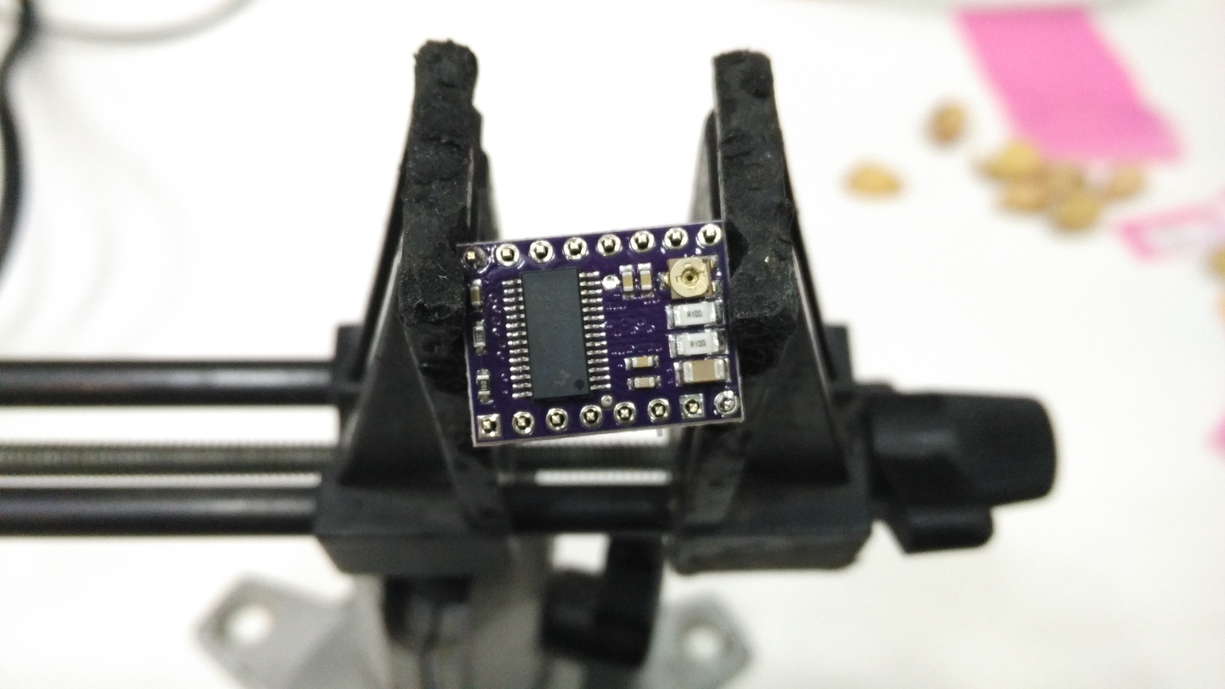
Electronica, to control the entire cnc system, we decided to use a shield for arduino (cnc v3), this plate has to connect 4 stepper drivers to control the cnc motors, in addition to being able to connect a pair of endstop, and the spindel.
Marc is in charge of installing the firmware in the arduino that is in charge of controlling the motors, as firmware we use the (https://github.com/gnea/grbl/releases) grbl, this allows us to control our motors using the programming code g-code.
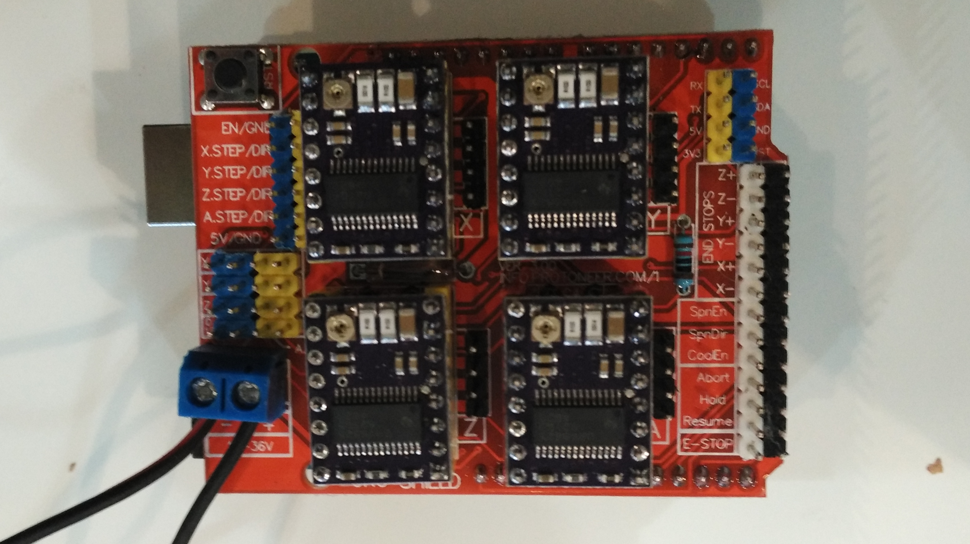
Here a small test demo of the motors with the contralodor, so that they work to their maximum current, it is necessary to connect them to a sources with amperimeter and to regulate the potentiometer of the driver until the consumption of current is the maximum, of this way us We made sure the engines worked perfectly.
