
Assignment


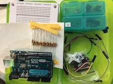
This week the Assignment is about programming our board to do something with as many different programming languages and programming environments as possible. I was working with Tom. We were following some tutorials from this Doc .
The first attempts didn´t work for me. I will explain more about this later because Guillem C.came to explain the tutorial of Arduino.
He showed as many diferent things very important to know because it is the way to understand how the boards work.
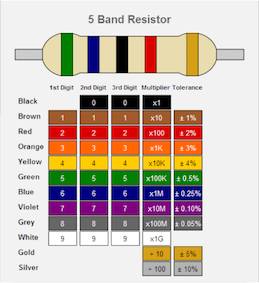
For example, what do the colors of the Resistorsmean.
Or how to calculate the capacity. Then he showed us how to simulate the conecctions with Fritzing and with Nico I did some test using Fritzing and Arduino. The first number of the ATtiny is the storage and the second is the group, which represents the family.
--->
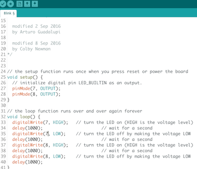
This was the first attempt with Guillem with and example of arduino, knowing that the short leg of the LED is the ground(-) and the other goes into the voltage (+). You can find the sketch here. 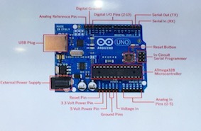
> 
Now we need to program the position of the components and upload the sketch to the board.

After this we used Fritzing to diagram a diferrent circuit with a Protoboard and egain programming with Arduino.
It is impossible to understand everything in the (ATtiny44A) data sheet so I began comparing with my schematic to find out the numbers in my ISP.


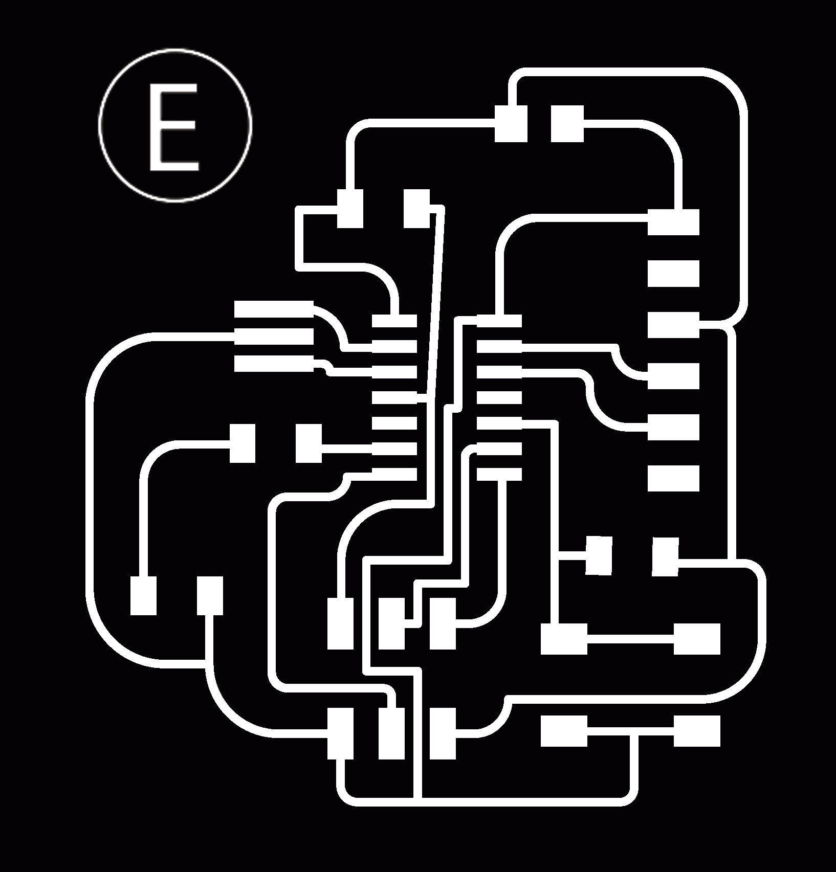
By comparing these diagrams, I understand in which place I need to conected the circuit. Then, I had to compare with the especification of arduino to program the "E ISP".
This is how my ATtiny looks compared to Arduino´s.

I followed these 2 tutorial 1, tutorial 2 from the docs.
to download Arduino. click there.
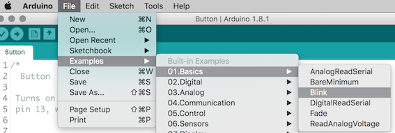
The First step when you get arduino and your computer is to load the ATtiny package into Arduino because by default ATtiny boards are not included into Arduino. Go on.
-"Arduino - Preferences"
-Find “Additional Boards Manager URLs”.
-Paste the following URL into the field (use a comma to separate it from any URLs you’ve already added):
https://raw.githubusercontent.com/damellis/attiny/ide-1.6.x-boards-manager/package_damellis_attiny_index.json
Click OK to save your preferences


"And like magic".
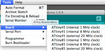
You have the library fo ATtiny in your Arduino.
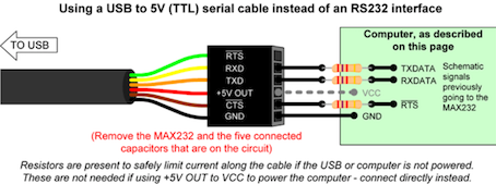
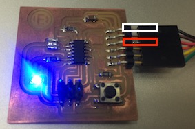
Now we have to connect the boar and wires. One important thing, you have to know the polarity of your board and the polarity of the USB cable. And you need the DRIVER of this cable.
Now I tried to program my ISP, first with a Arduino from tomas, then with my FabISP and the last one with the programer of the lab "AVRISP mkll". I had a lot of trouble because in the first moment I didn`t understand what was happening.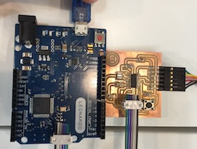
I set up Arduino like this.
But everytimes I had problems with the "Burn bootloader", this mistake.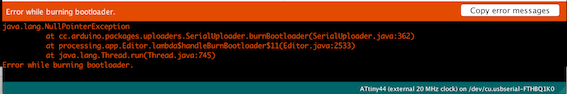
---->
IPS Box
The mistake was discovered by Tomas which was the clock that was solded wrong. I remade the welder and now it works!
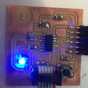
After I was trying to connect the ISP scheduled to a battery, the problem is that the ATtiny can`t receive more that 5v so I joint two batteries of 1.5v and did the circuit.
Thats works very good and then I made a box to keep all that in. I used Rhinoceros and did a 3d print.

