Week 08:Embedded Programming
This week's agenda for Fab academy was :
Read and understand the data sheet
Make your board do something by programming it in possibly different languages.
Embedded Programming
For the first part of the assignment, we had to read and understand the DATA SHEET. For this , I first started with the basic Attiny microcontroller, and started with understanding the pins of the attiny.

After understanding the pin out and reading through the data sheet, I also found Sparkfun Learn to be a very useful resource in learning about electronics and its theories.For understanding the basics and the most commonly used terms in embedded programming and its meaning, I found this page on spark fun very useful to start with, HERE.
For programming my board, I used the board I made in Electronics design week. Here, as beginner, I am going to keep it basic and try to program my board to light an LED. But also, while understanding the data sheet and studying about Attiny, I understood, that if I want to program my Attiny with more libraries and multiple code,like for example the CapSense Library in the arduino IDE, It is better to use Attiny 84 or 85 than the Attiny 44 or 45. This is because, the memory available in an Attiny 84/85 is more than the memory in 44/45 although the pins are the same.But since I am a beginner in the world of electronics, I programmed my board to light an LED.
To start off, we must have the Arduino IDE
Once we have Arduino, we must download this file, so that we have the Attiny libraries, Attiny libraries. once you have the link downloaded, follow the instructions on the webpage to have the attiny board shown in tools- board.
After the board is shown on the arduino IDE , its time to program the board!
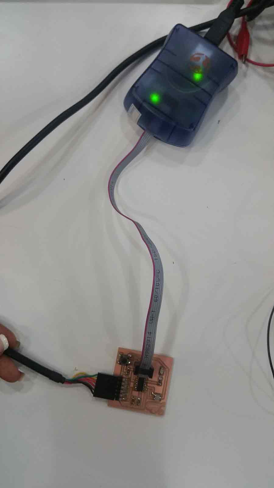
Connect the avr or Fab ISP to the board designed.Here, I used the AVR ISP , and made sure the VCC, GND, MOSI, MISO, SCK, RST is connected in the right way.
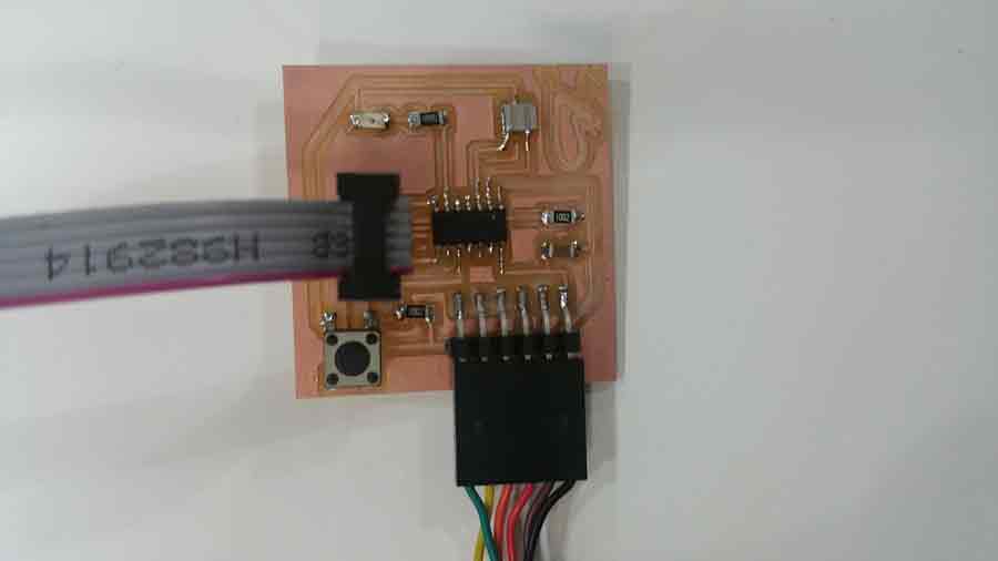
once all the right connections are made, you should have the green light on the AVR, confirming the connections are right.
Now that the board is connected, I opened the Blink example on the arduino IDE, SELECTING ALL THE RIGHT BOARD, PORT AND ISP, we can click on Burn Bootloader.
What this arduino code is essentially doing is, It turns on the Led by making the voltage high, and keepin it that way for one second. After one second, it makes the voltage Low and therefore turning off the LED for one second. It repeats thhis process.I also learnt that, we can change the time taken to turn it on and off by changing the delay time.
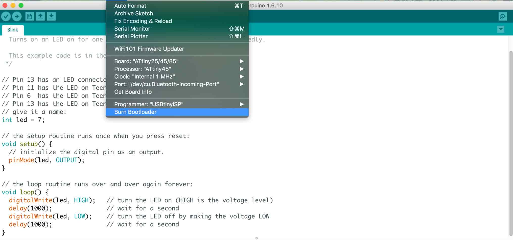
One more important note here is, The original code in arduino says LED pin 13, based on the ATmega in the arduino board, But for the ATtiny, the LED pin is connected to pin 6 and for arduino programming it is considered as pin 7
// Pin 13 has an LED connected on most Arduino boards.
// Pin 11 has the LED on Teensy 2.0
// Pin 6 has the LED on Teensy++ 2.0
// Pin 13 has the LED on Teensy 3.0
// give it a name:
// Here as we are using ATTINY , we are going to define the pin as 7
int led = 7;
// the setup routine runs once when you press reset:
void setup() {
// initialize the digital pin as an output.
pinMode(led, OUTPUT);
}
// the loop routine runs over and over again forever:
void loop() {
digitalWrite(led, HIGH); // turn the LED on (HIGH is the voltage level)
delay(1000); // wait for a second Changing the delay time from 1000 to any other number wiill change how ling it takes to blink the LED
digitalWrite(led, LOW); // turn the LED off by making the voltage LOW
delay(1000); // wait for a second
}
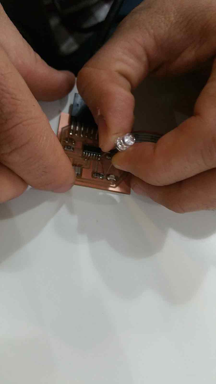
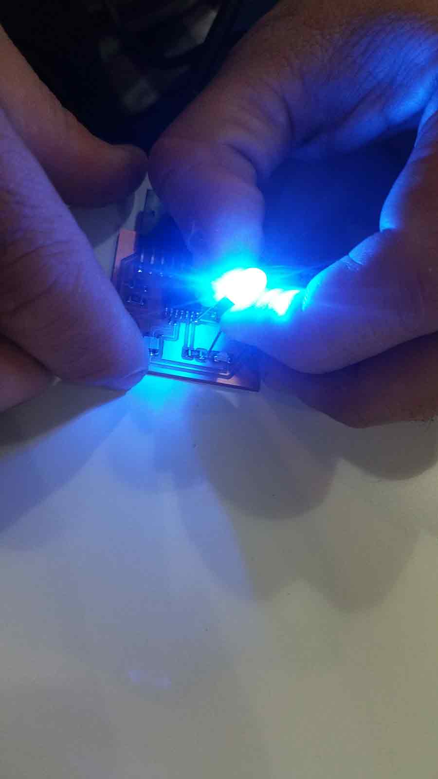
If everything has goes right, then the LED should start blinking! I made a small error, I connected the LED in the wrong direction, hence, here you will see me connecting the board with an actual LED .
Here I also toyed around with the idea of maing the LED blink in a 2 alternating loops. In this code the LED blinks faster for the first 3 blinks and the delay is lengthened and doubled for the next 3 blinks.And this happenes in loops.In the code , you can see that I have set the value of n for less than or equal to 3 with delay of 500 and the next n value with less than or equal to 6 with a delay of 1000.
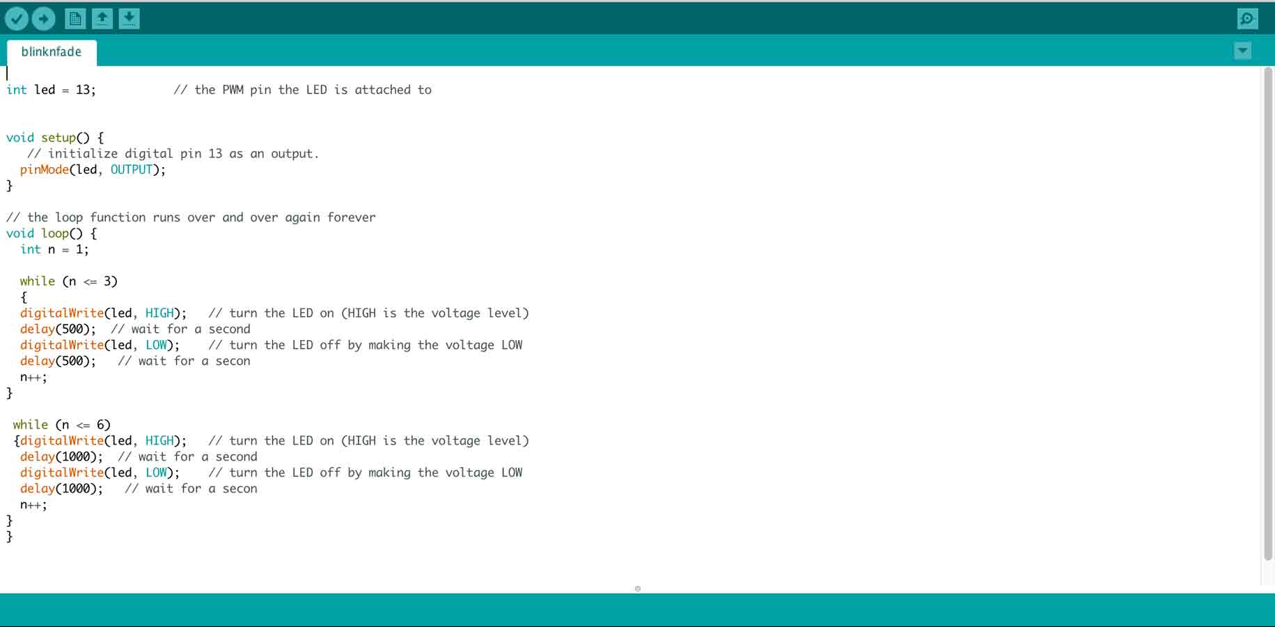
code
int led = 13; since this experiment is with arduino, it is pin 13 for attiny it is pin 7 // the PWM pin the LED is attached to
void setup() {
// initialize digital pin 13 as an output.
pinMode(led, OUTPUT);
}
// the loop function runs over and over again forever
void loop() {
int n = 1;
while (n <= 3) Here is where we can change the number of times you want to alter the blink speed in the first few led blinks, so here for the first 3 led blinkc the delay is 500
{
digitalWrite(led, HIGH); // turn the LED on (HIGH is the voltage level)
delay(500); // wait for a second
digitalWrite(led, LOW); // turn the LED off by making the voltage LOW
delay(500); // wait for a secon
n++;
}
while (n <= 6) Here is where we can change the number of times you want to alter the blink speed in the second set of led blinks, so here for the second set of 3 led blink the delay is 1000, but the number is 6 as it takes into account the first 3 led blinks in the first cycle as well, therefore , after, playing this in loop
{digitalWrite(led, HIGH); // turn the LED on (HIGH is the voltage level)
delay(1000); // wait for a second
digitalWrite(led, LOW); // turn the LED off by making the voltage LOW
delay(1000); // wait for a secon
n++;
}
}
Here is a video demonstrating the idea.
view and Download the code here
To download files click HERE