Week 07 : Computer Controlled Machining
This week's agenda for Fab academy was :
Design an Object to be milled
Understand the process of trasfering the 3d file to the machine by generating a G-CODE
Mill the design to have a working product
3d modelling and design
For the design, I initially conceptualised an object that can be used when milled from ONE single peice of board and can be attached to make an object, This was important for me while going about this assignment.The problem was when I took this concept too far and decided to make a bed from one peice of board, that can be tied with a tent material for shelter from the top.
I spent a lot of time drawing and figuring this. The designs were also made ready, and this is how the design looked.
A bed that can be milled from 1 sheet of wooden board. And later be folded when not in use or spread out to sleep on.
And all this fit on one sheet of wood, the size of which would be, 2500 X 1250.Before milling the whole design, I wanted to first check if the design, Flexure most importantly would bend and work.
So, I made a test.
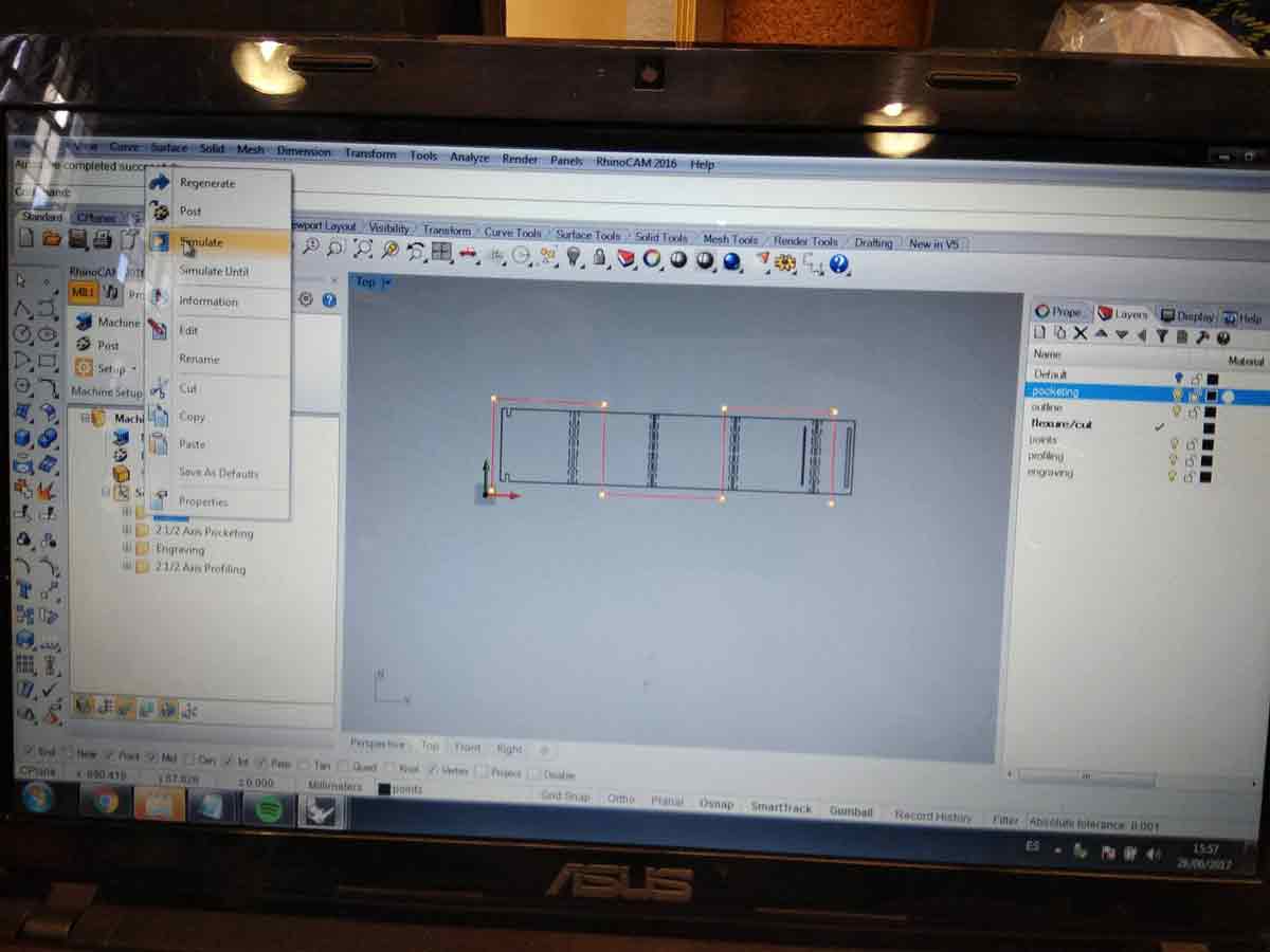
For the test, I needed to make the strategies on RhinoCam
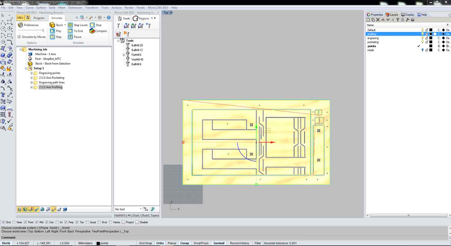
I will take you through the steps of how arrived at these strategies
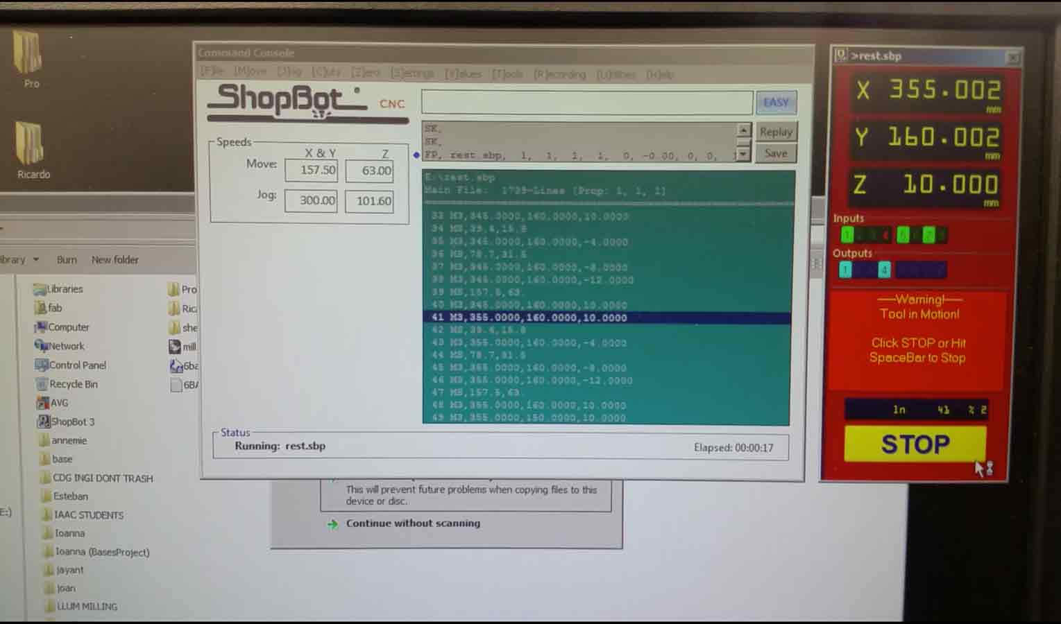
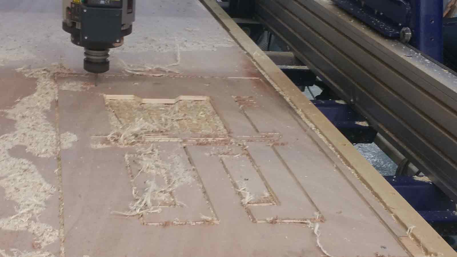
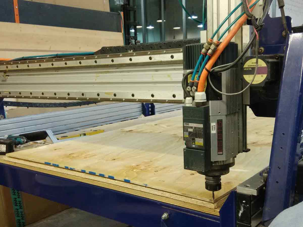
Here you can see , once the gcode is sent to the machine, it starts reading the gcode and cuts the file.
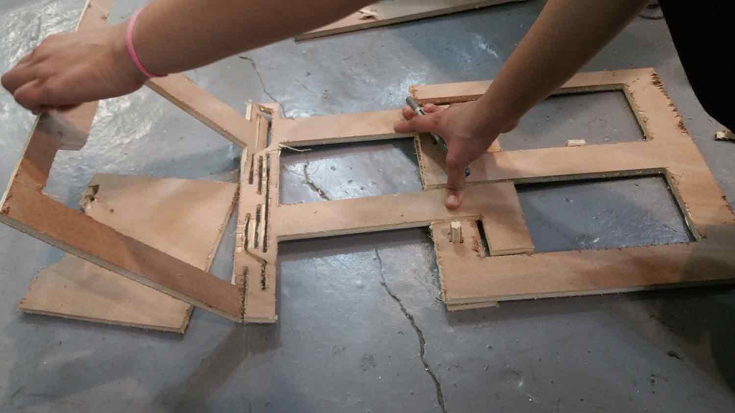
This test was very good, As I understood, what are the things that worked and what dint. The flexure detail fortunately worked, But Some parts of the design needs to be changed. I also dsigne dthis in such a way that the material could be kept in place by another small peice of wood in the pockets, Unfortunately this did not work. Hence other materials will be essentially required, atleast like screws etc
I want to thank Citlali for helping me through the process of milling .
Since the concept of making everything including the details to attach the peices to each other dint work, I thought of making something else like a chiar with the similar concept.In this design, one long sheet has flexure at every 500 mm and it bends around each other to form a box like structure, on which we can sit with a small extrusion for back rest.
I want to thank Matteo for helping me with using the shopbot.
In this, you can see that I have set up the strategies as explained in detail, point wise, above.
Once the strategy was set up and the gcode exported, I sent the gcode from the computer to the machine. But , before we start, we have to lay the material on the ShopBot bed, and screw the material to be cut on the buffer layer on top of the bed, to make sure the material does not move or flip while the machine is cutting.
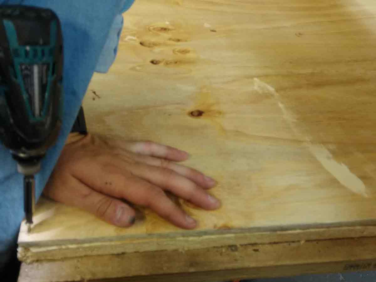
Once the material is screwed tightly in place, we set the x, y and z co-ordinates of the machine to tell the machine where to begin the process of cutting.
Once the machine took over and finished the cutting , I took my material out, the one single cut peice to form a stool and the left over material and Dont forget to clean the bed of the Shopbot for the next user.
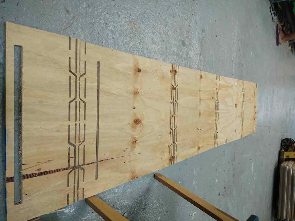
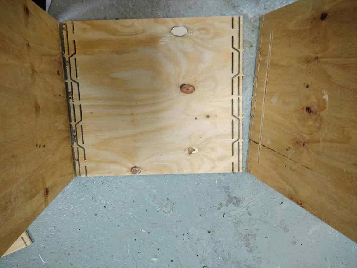
Unfortunately, What happened in this test was, the flexure of the previous test was slightly modified and what was working previously should have been kept the same!but :( . Hence the peices did not assemble together.
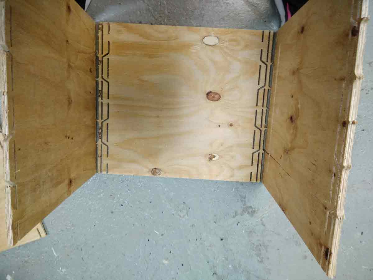
Here, you can see that the flexure pattern dint work unfortunately. The only difference, I mirrored the flexure pattern to get more curvature, but this dint work unlike the previous test which worked but had less curvature.
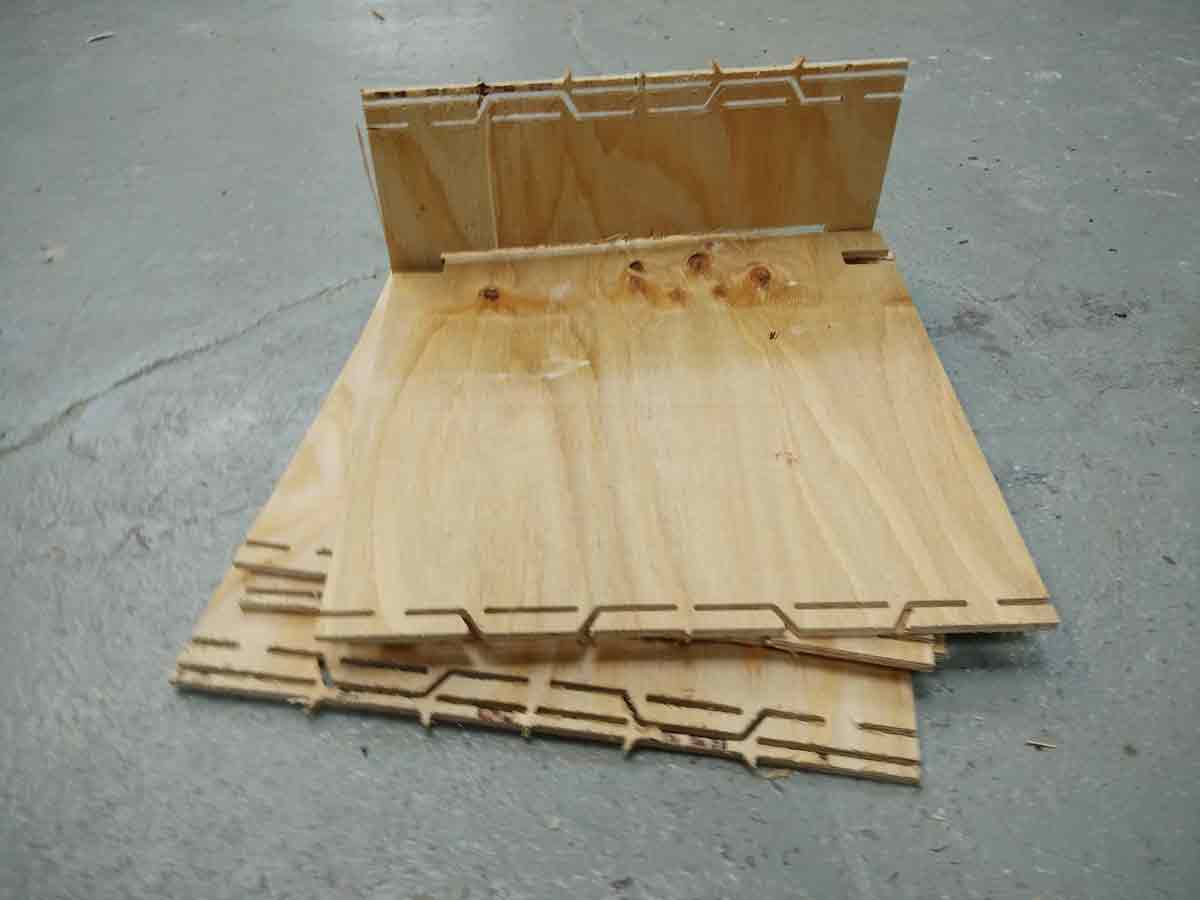
This image below was supposed to be the back of the chair which is not exactly a back rest but was supposed to add to the design.
To view and download files click HERE
To download files click HERE