Week 03:Computer Controlled cutting
The agenda for the week was :
Learn the tolerences of the laser cutting machine
To make a paremetric model using pressfit joint
Learn how to use the Vinyl Cutting machine and apply this learning to vinyl cut your own project/or use the method in a project.
Laser cutting and Vinyl cutting
This week was our first step towards fabricating projects. We learnt about techniques of laser cutting.We also learnt how to do vinyl cutting using the Roland machine at the Fab Lab.
1.Vinyl cutting _ I used this technique to make a project I had been wanting to make for almost a year now. Thanks to my Fabricademy bootcamp, I got access to the materials that are required to make an electroluminicent panel. This is a technique used to light a panel with electricity which is a result of chemical reactions due to the paste/liquids applied on the panel.
The experiment that follows is taken from this tutorial. One important thing I learnt from this experiment is, The paint has to be really good qaulity in order for this to work. Only after many attempts of failure were we able to finally arrive at the result.The tutorial in the video makes it seem like a flawless easy way of doing the EL panel, but one extra layer of paint, or varied thickness, or unchecked positive and negative side of the panel, and the experiment will ot work.
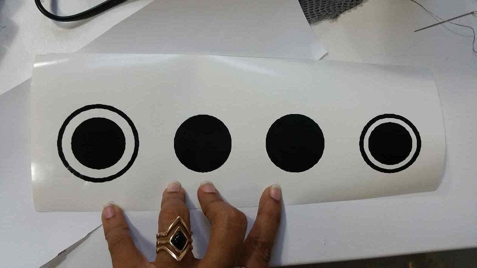
I made the drawing on Rhino and imported the file as an Illustrator file on "Cut Studio" software from which the Roland cutter takes the file to print.

The circles are required to be cut , so that the electroluminiscent paint can be contained only in that area. The next step was to insert a required measurement of material into the printer.
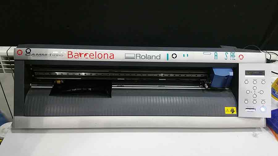
As My material is not a roll of paper , I select the option of piece on the machine and not Roll , so that the machine then understands and scans the peice of paper and analyses the measurement of the sheet. This measurent is directly updated on the software on "cut studio" on the computer and we can select the option for cutting measurement as - from the printer.
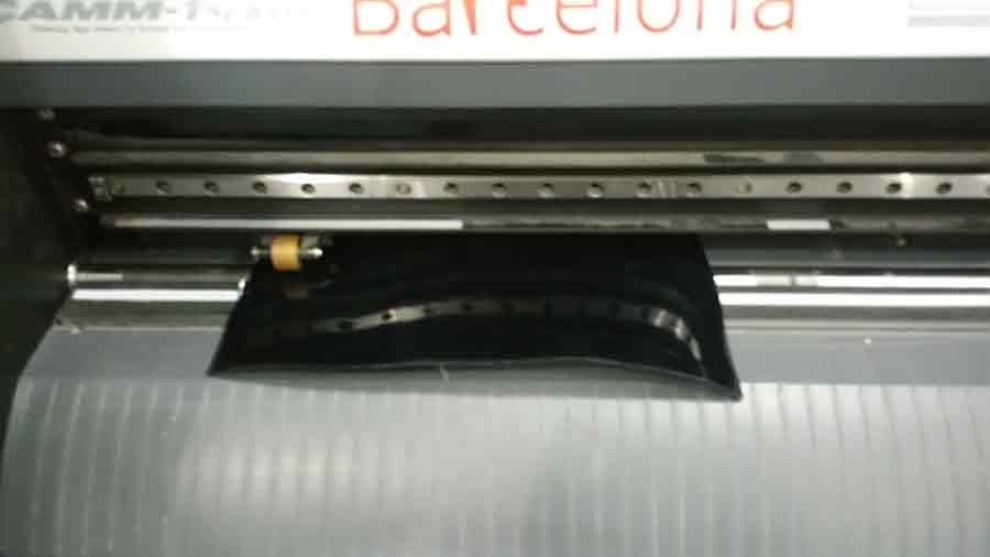
When we add the peice of paper in th eprinter , it is very important to note the paper id within, atleast, 2 rollers which can be seen in the image below and the rollers are place in the appropriate position on the printer within the guid lines. Only then will the machine understand the area to be printed and take it as an input,else it does not consider the sheet for printing.
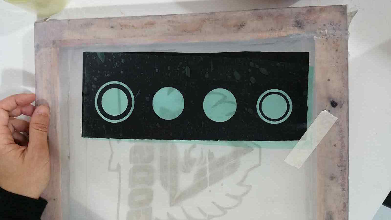
Once the sheet is cut to my desired design, I then add a Transfer paper on the cut print to make sure my design comes of the vinyl sticker in the same line and alignment.
Now that all the peices are on th etransfer sheet, I can transfer the cut peice in the exact alignment onto the conductive glass.
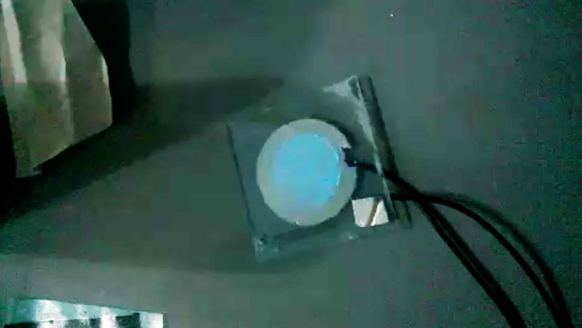
Once I had all the processes done,i.e., Applying coats of the electroluminiscent pain etc, This is how the electro luminsicent panel it up.
Laser cutting
2.For the laser cutting exercise, I used the laser machine to make a pressfit laser cut lamp after parametrically modelling it using grasshopper and Rhino.
But before we move on to my experiment, let me first discuss the group assignment we made in order to test the parameters of the laser technique.
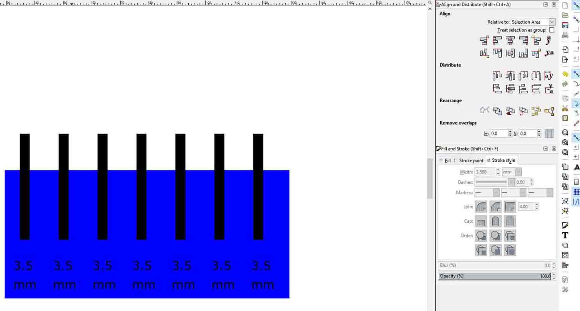
For our group assignment, we tested varied tolerences,for the cardboard material we were using for our following project for the assignemnt.first we used inkscape,in order to make the drawings.
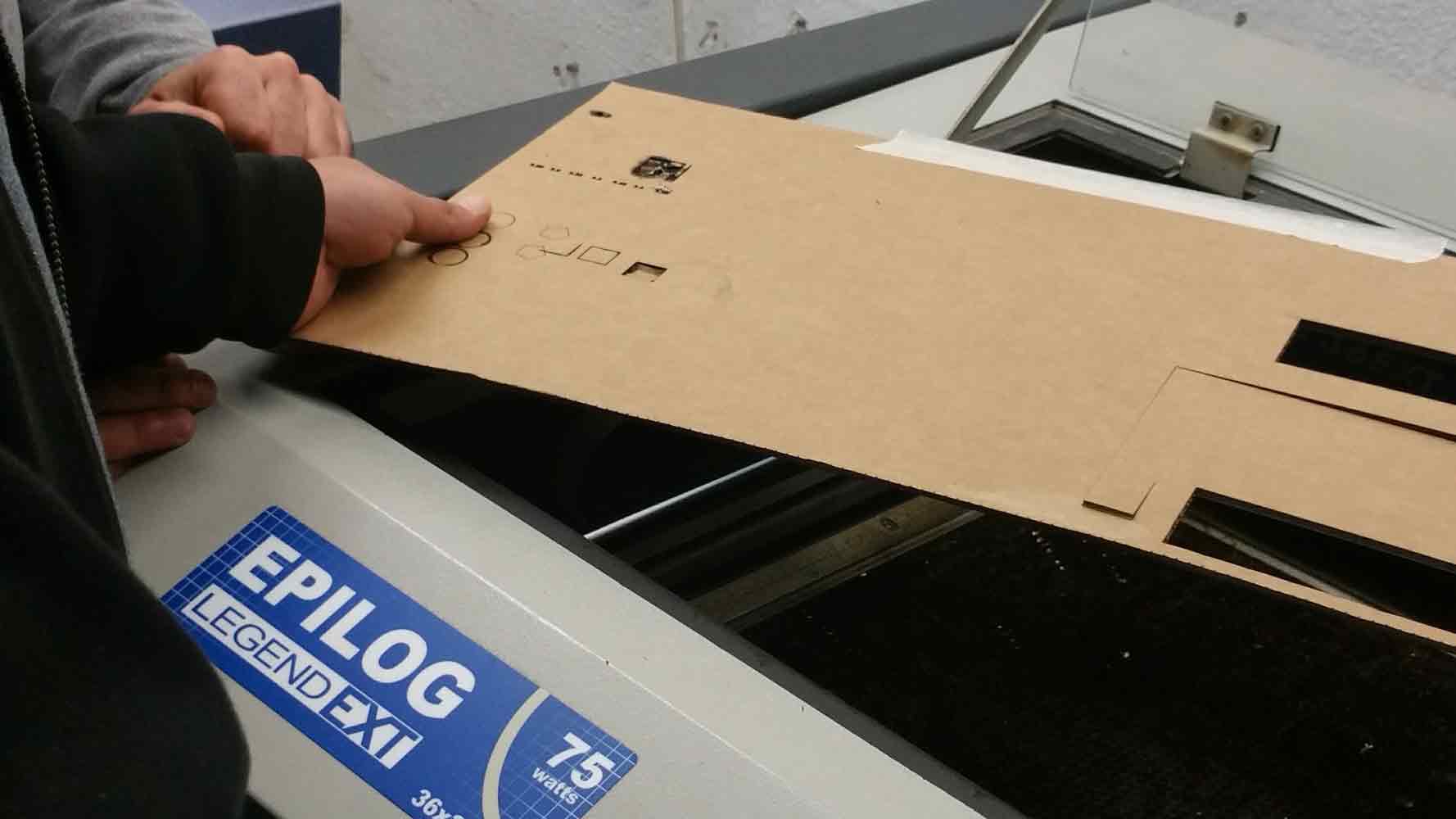
Once we had the drawings, we put it onto the machine to test our drawings.first we made the intial cut test for understanding the right speed and power at which the machine would cut the material appropriately. we used the settings that is mentioned in the Parameters for laser, Fab Lab Barcelon, a list that is online, and we checked for cardboard.For this specific exercise, we used Speed of 12 and Power of 90
After our general tests to get the right specifiactions for cutting through the material, we set out to cut our tests in order to test the tolerences for our material for a pressfit construction.
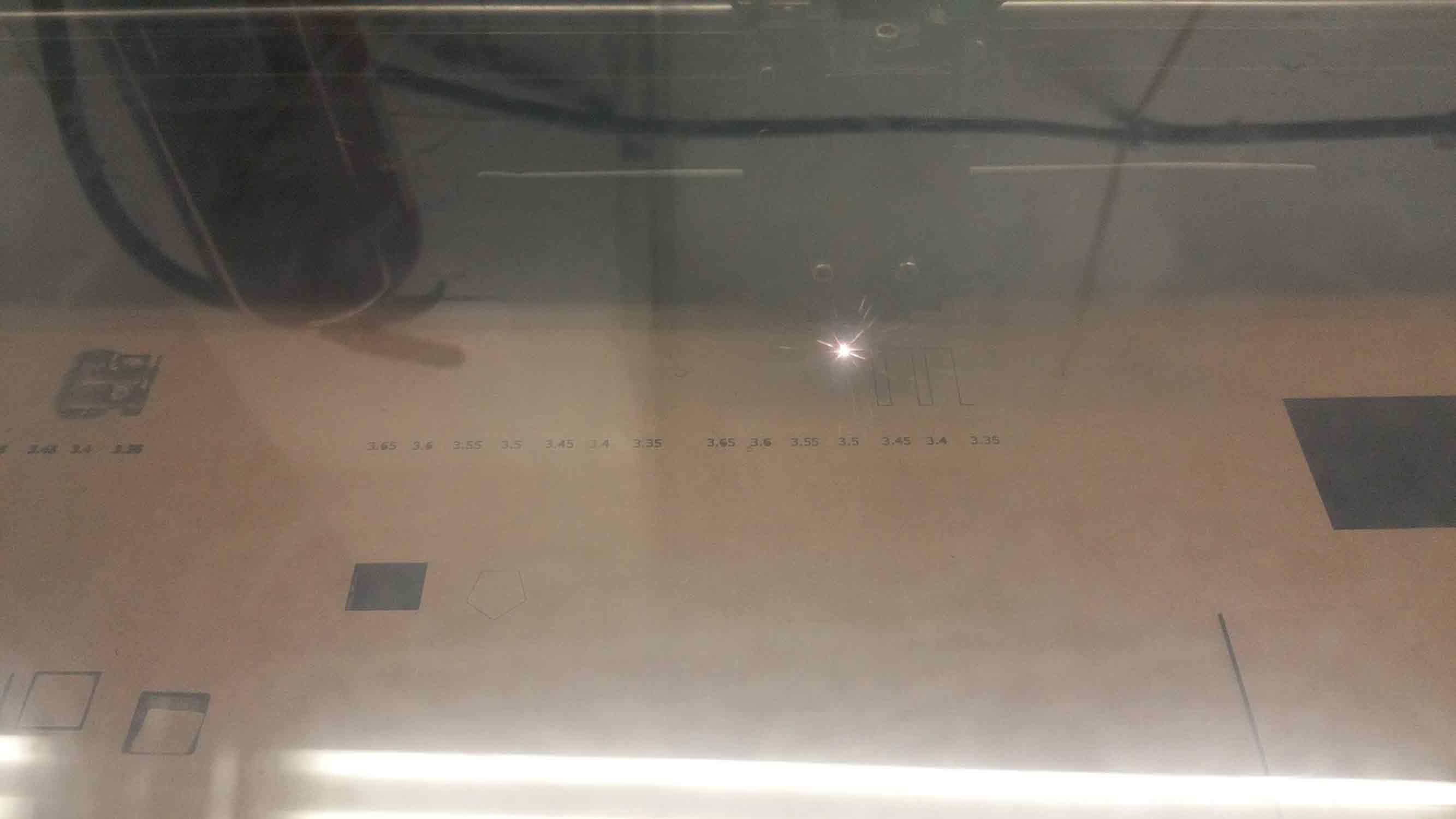
The material given to us was carboard with 3.5 mm thickness. we tried tolerence of 0.5 mm difference inorder to check which makes the perfect cut for press fit joint.
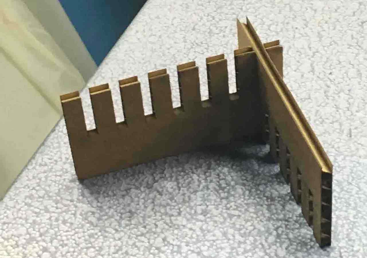
After this group experiment, we understood that the laser has a set of tolerences that needs to be checked before cutting.
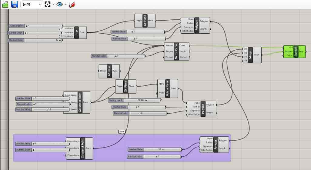
For this exercise, as a part of my individual project, I designed a parameteric lamp using softwares like Rhino and grasshopper.In this grass hopper scrip, I first define 3 co ordinate points in x, y , and z. At these points a plance is constructed. The size of these planes can be moade bgger on smaller using the slider.These planes can further, be rotated and the number of sides on the plane can be changed, This forms the axis at which the geometry is merged and a shape is arrived at.
Once this was the grasshopper script was ready, I tried various geometrical output by altering the parameters.
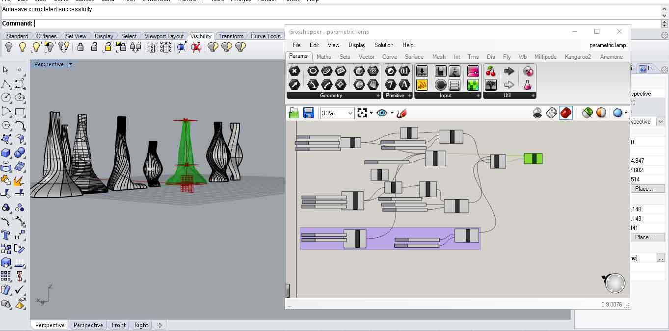
After trying out a few geometries, I was most inclined to this one
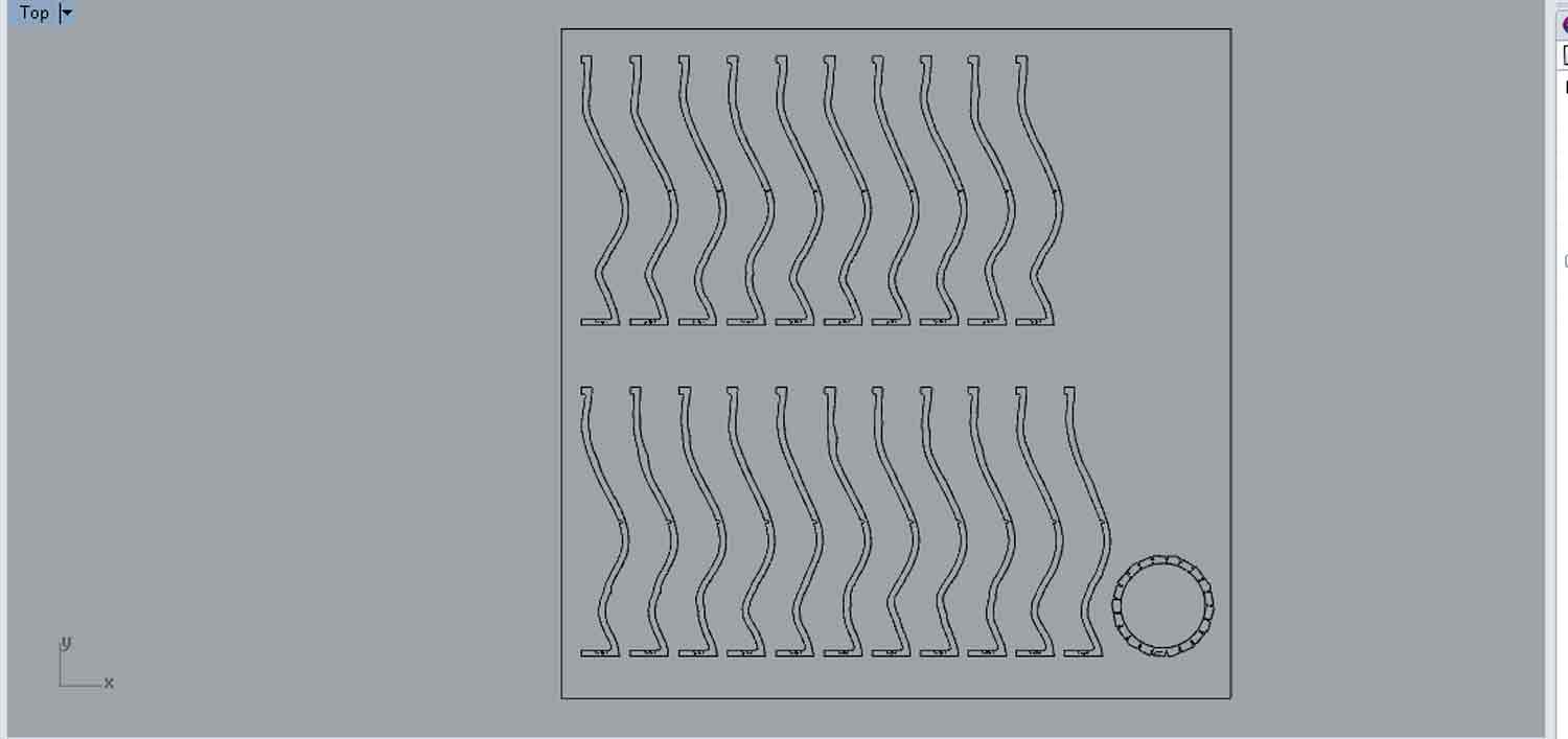
Since the agenda of the laser cutting exercise was to make a pressfit design, I wanted to incorporate this technique in making a lamp. I used Autodesk Make 2d to get quick drawing for lasercutting. It is a beautiful software, but the recent update is that they have discontinued the software and added those features on Tinkercad etc. Once I got the drawing from Make2D, The drawing looked liked this.
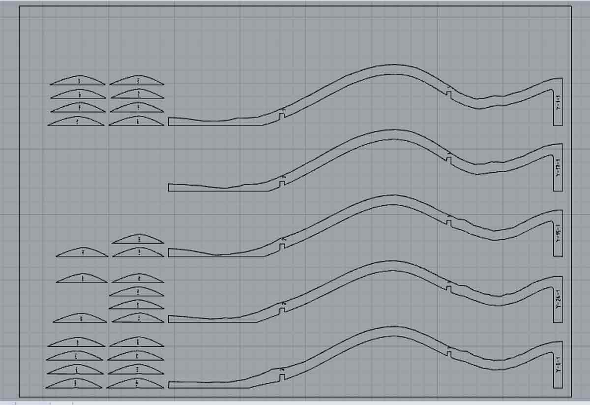
Once I got the drawing I arranged them in the size of the board and exported the drawing as .dxf before sending it to the Laser machine.You set up the file To print and once the file is set up in the right size, for the machine settings, I used the speed of 12 and power of 90 .
The material we could initially use was Cardboard, But This material did not work as the pressfit peices were too small for the lamp to be sturdy. hence unfortunately , I could not assemble my lamp and the peices tore apart.
T R I A L 2
In this trial, I tried to learn from my previous issues in the execution of the lamp. Th issues were, the slices joining to form the lamp were too thin, the material was too fragile, and the width of each size was less.
In this trial, i rectified those errors, and now the height is double the previous height of the lamp , and the width has been increased of each slice, so it would not be too thin to hold and press fit. And also, I have only one connecting member now, as apposed to the smaller 3 connecting members previously.I presumed this ahould be enough.
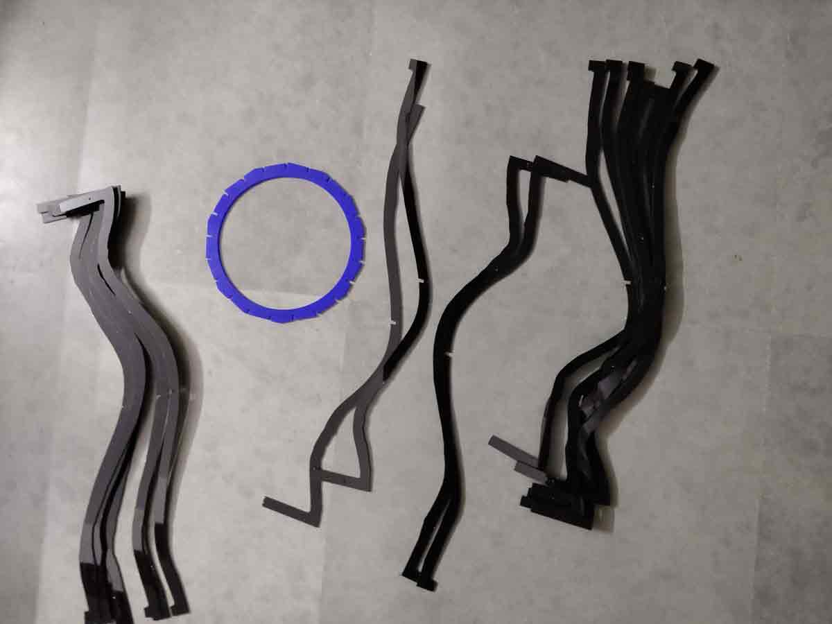
I used acrylic material to make the lamp. Once the file was cut in the laser, I had these peices to press fit.
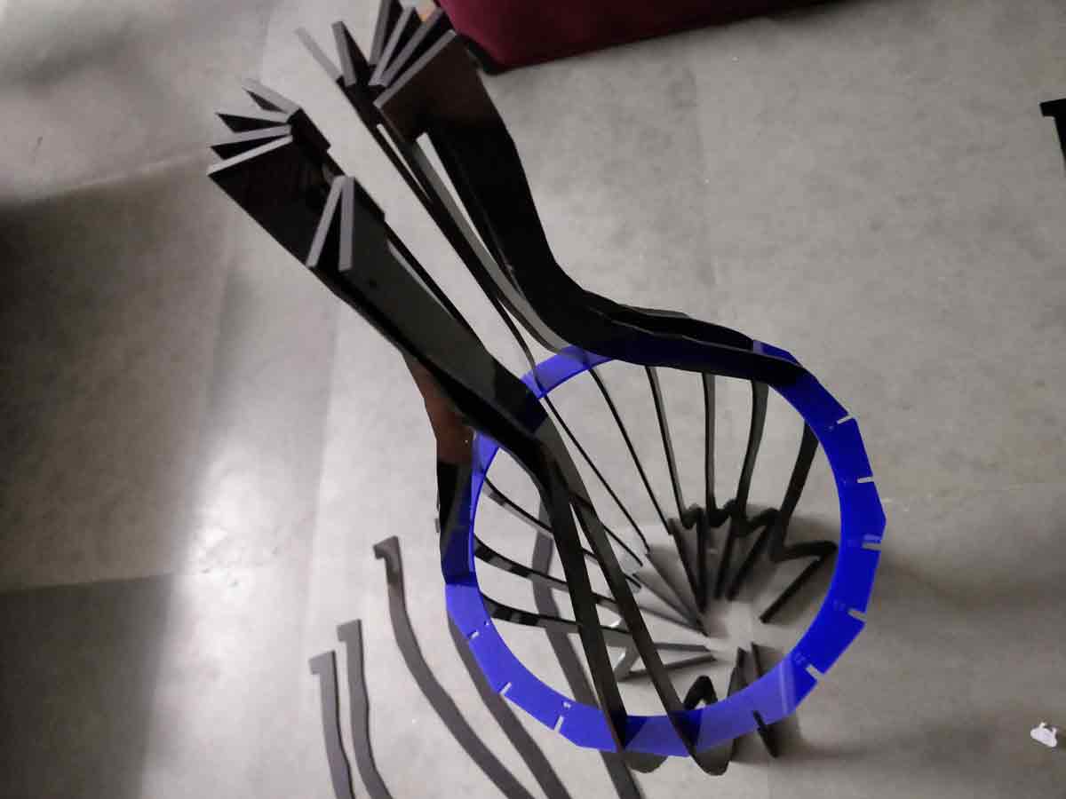
A process image of putting the peices together to make the lamp -
Here is how the lamp looks after it is assembled.
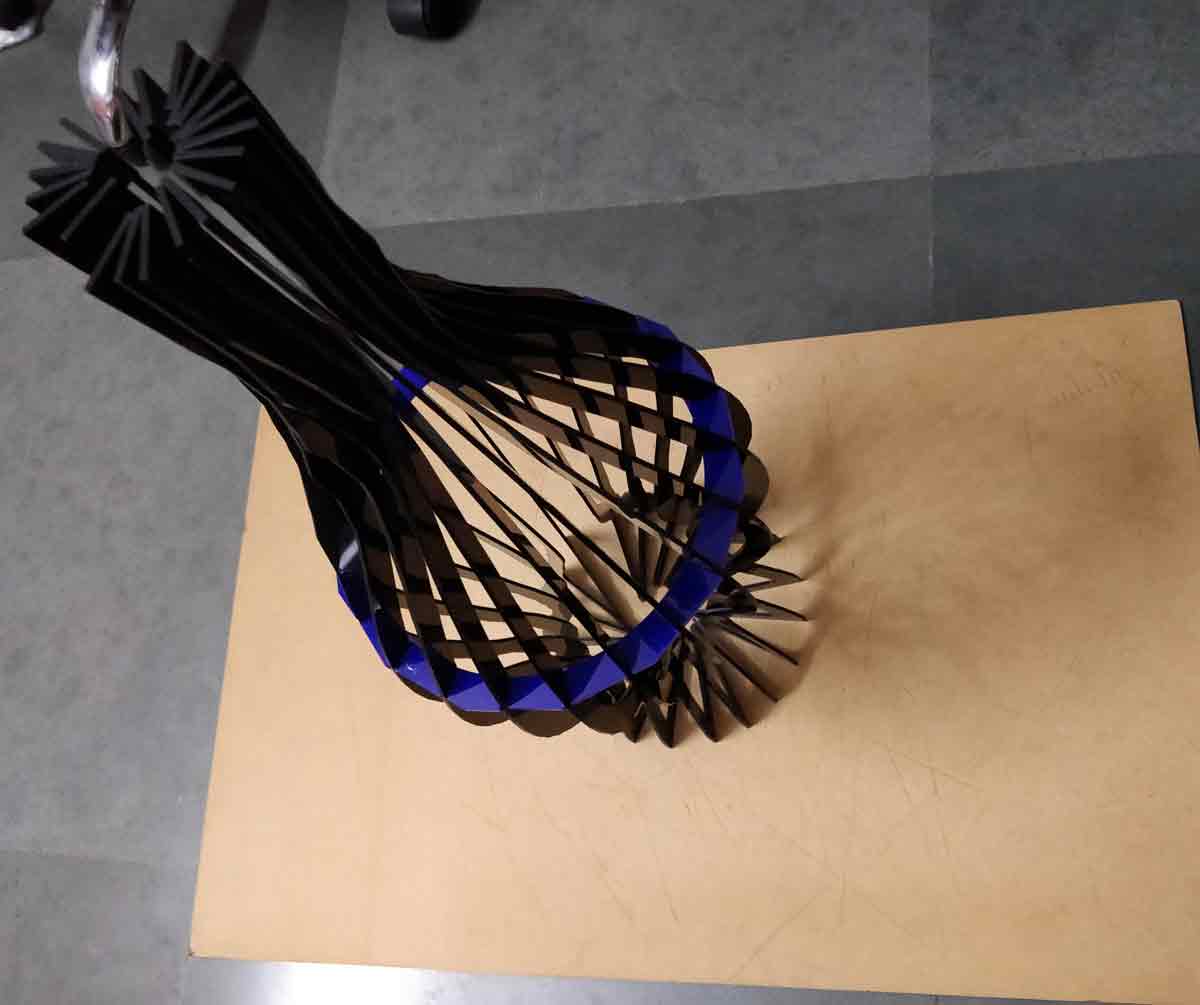
The twisted pressfit lamp -
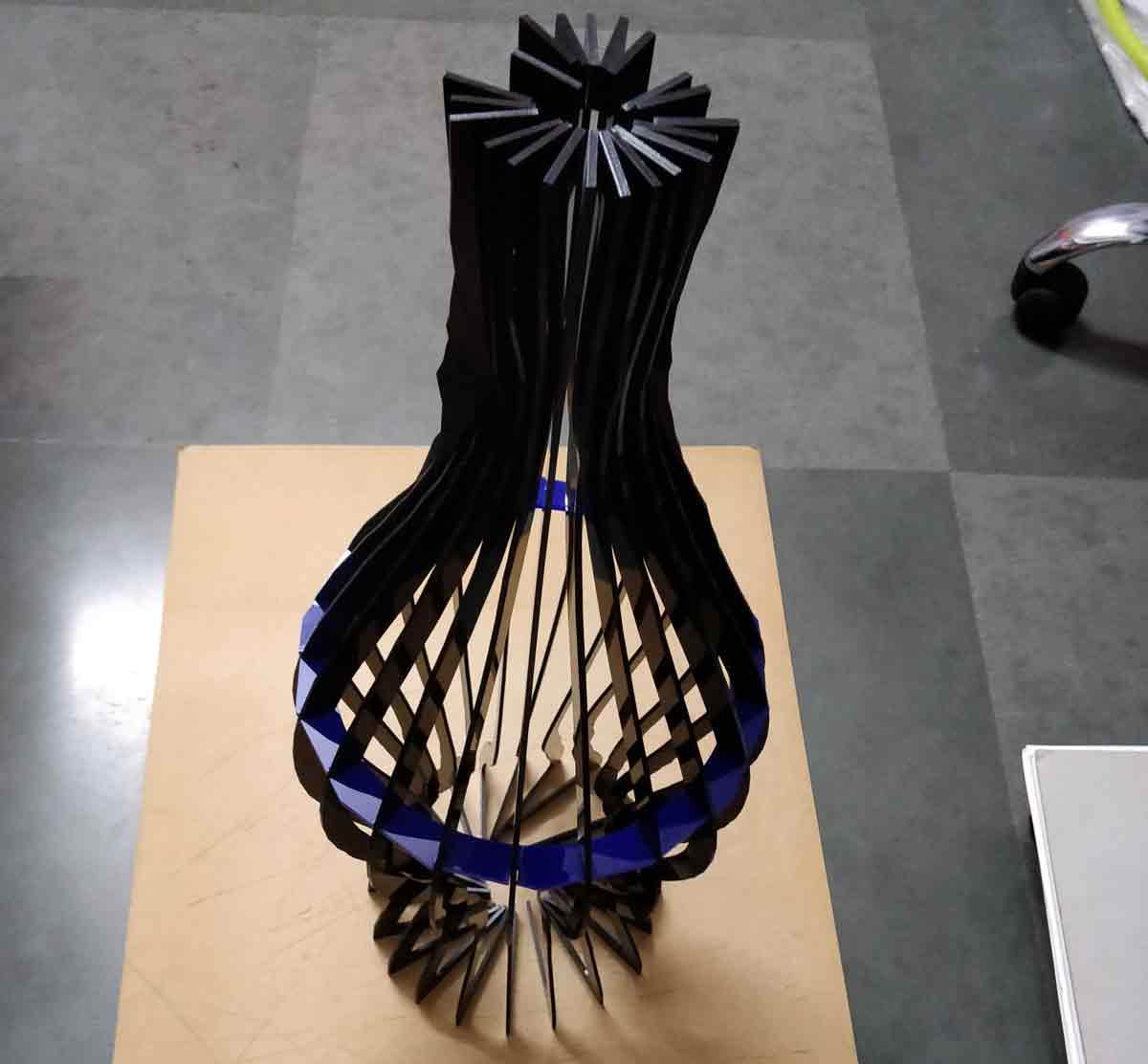
I ama glad I tried it the second time around, I am quite happy to see the 3d in an actual product.
To view and download files click HERE
To download files click HERE