FOURTH WEEK
-Electronics production-
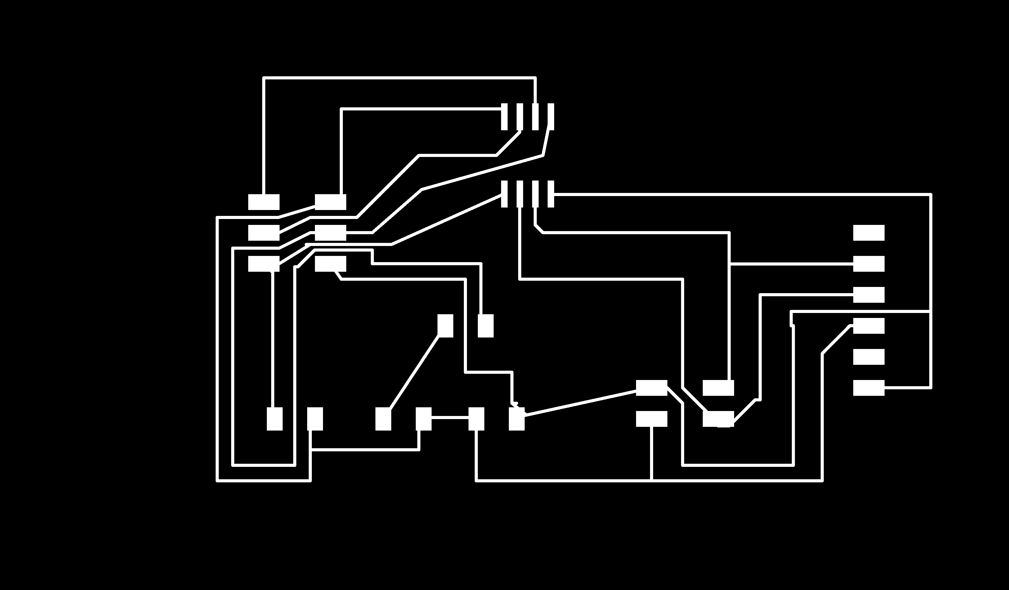
ASSIGMENT: make an in-circuit programmer by milling the PCB.
1. First of all we turn on the machine.
.
2. We prepare the bed of the machine in case it needs to be replaced. If not we make sure it is clean. In my case I used the copper it was already placed in bed.
3. I introduce the end mill size I want to use. In my case I will use a nozzle of 0.4mm of diameter to mill the traces and a different one for the cutting boarder. It is the tool you see behind to screw and unscrew with the two hands. They are delicated and small tools to work with.
4. Once I have put the end mill I need to place it in the right height which is the Z calibration. To do so I unscrew the end mill and let it fall until it reaches the copper plate.
5. Once the machine is calibrated and with the right end mill we open the computer and we see where are located the png files that we want to mill. In our case it is inside the projects folder. I choose to make the Brian example. So let's prepare the file to start milling.
6. We double click the folder in the desktop called mods mode and it will open a window like the one behind:
7. Select the Open server programs option.
8. Select the PCB.
9. It will open a window like the one below. Don't be scared! Here is where we will define the milling quality.
10. We will upload the file we want to mill and once you select it you can see it in detail in view option.
You should see the image charged in here.
11. Once we have upload the png image we go to the next square that says set PCB defoults and we click in the mill traces option.
12.In the next square it is about the outlines and the depth of the milling lines so we like the default settings and we will not change them. To see the resoult we click in to calculte option.
13.In the next square is where we define our 0 starting point or origin. In my case I place it in the x:20 and y:80. This numbers I will write them down for later write them again for the second file.
14. Now that we have our file uploaded, our calibration done and defined our 0 starting point we just miss open the connection throught the computer and them machine. To do so we will double click in the file of the desktop that says Serial open and we will wait until we see that it says open.
15. Finally we will go back to the last square and we will see an option of calculate again. The reason why we calculate again is because we calculate before defining the 0 point and now that we have it we need to do it again. The machine will start milling in that specific point. Once you click it will start milling the copper.
16. Finally we will click the option at the end that says send file and after it the machine will start milling the board.
17. Once the machine starts milling we will cover it for the sound with a plastic protector we have and also a wood one. Sometimes it can be anoying the sound of the machine.
18. Once the machine has finished we will just see powder of copper so we will need to remove it to see the work. We will use a brush and with the hand we will clean it.
19. This is the resoult but we are not finished.
20. After milling the traces we miss cutting the border and to do so we will change the nozzle for a different one more thiner one.
21. We will place and calibrate again the Z which is the height and we will make sure it touches the copper bed.
22. We will open again the folder and this time we will select the second png file with the name of mini_cut. It is the outer line we want to cut throught the copper.
23. We will repeat the same process without changing any of the settings excpet the X and Y. We will write the same points as in the previous file in order to start in the same point. In my case where X:20 and Y:80. And the resoult is the following:
24. Again we have powder and we can not see anything. This time we will use the little vacum and clean all the bed to see our work.
25. To take out our work we will use a spatula and very easyily it will come out.
26. Here we have the resoult.
27. It is very important to clean the board with water and soap.
28. LETS GO FOR THE SOLDING PART. Once we have our board milled we go to the electronic space where we can find all the components we need.
To program the board you have to plug the USBISP programmer and open the Git Bash and type: avrdude -c usbtiny -pt44
29. The list of the components we need is in the week asigment inside Brian. It is the following: 1x ATtiny45 or ATtiny85, 2x 1k resistors, 2x 499 resistors, 2x 49 resistors, 2x 3.3v zener diodes, 1x red LED, 1x green LED, 1x 100nF capacitor and 1x 2x3 pin header.
30. This is the fisrt time I have sold and worked with this miniature things.
31. Before solding we will prepare all our toold to work properly. One solder and a base, a wet sponge to clean the solder, SMD Only as the material for solding, double tape, tweezers to take the components and a lot of patience.
32. The tape is basically to stick the board on the table to avoid movement while we sold on it.
33. You will see that when you sold there is a hard smoke so try not to breathe it and that is why I used the help of this ventilator.
34. It took me so long and a lot of patience to sold such tiny things. But finally I got it!
35. To check that the solding is good and there is no short I used this tool that by beeping you can analyse the shorts.
MISTAKES DURING THE PROCESS
I had to repeat the milling because the first board I milled I didn't calibrate well the Z axis so it didn't remove all the coper parts I wanted.
SECOND PART
The next step is to program the ATtiny45. To do so I used the same link as before and following all the steps.
How to program the board?
To program the board you have to connect the USBISPprogrammer in the computer and first of all try to see if the compueter reads it. To do so we open Git Bash and type: avrdude avrdude -c usbtiny -pt44
If it reads it it will appear a message saying that the Fuses are OK.
Files