Week no. 13
Input Devices :
- measure something: add a sensor to a microcontroller board that you have designed and read it
Board Design
This week’s assignment is to measure something.
Since final assignments deadline is getting closer
I’m trying to make things that I can use for my final project as well.
I want my brake light to have to detect the movement, that could activate the LED as you brake.
So for this week’s assignment I wanted to make the accelerometer board.
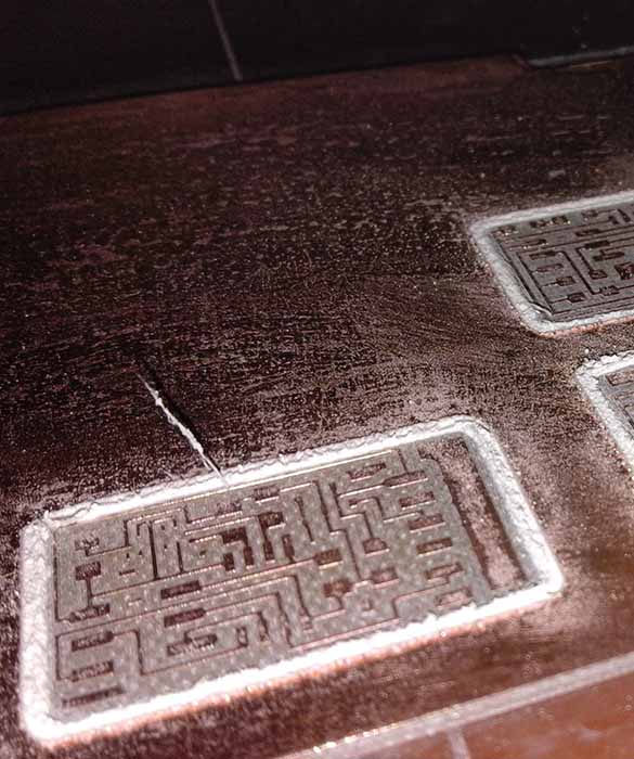
I’ve looked at Neil’s designs for the accelerometer board and tried tho designed it myself:
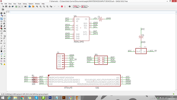
Schematic :
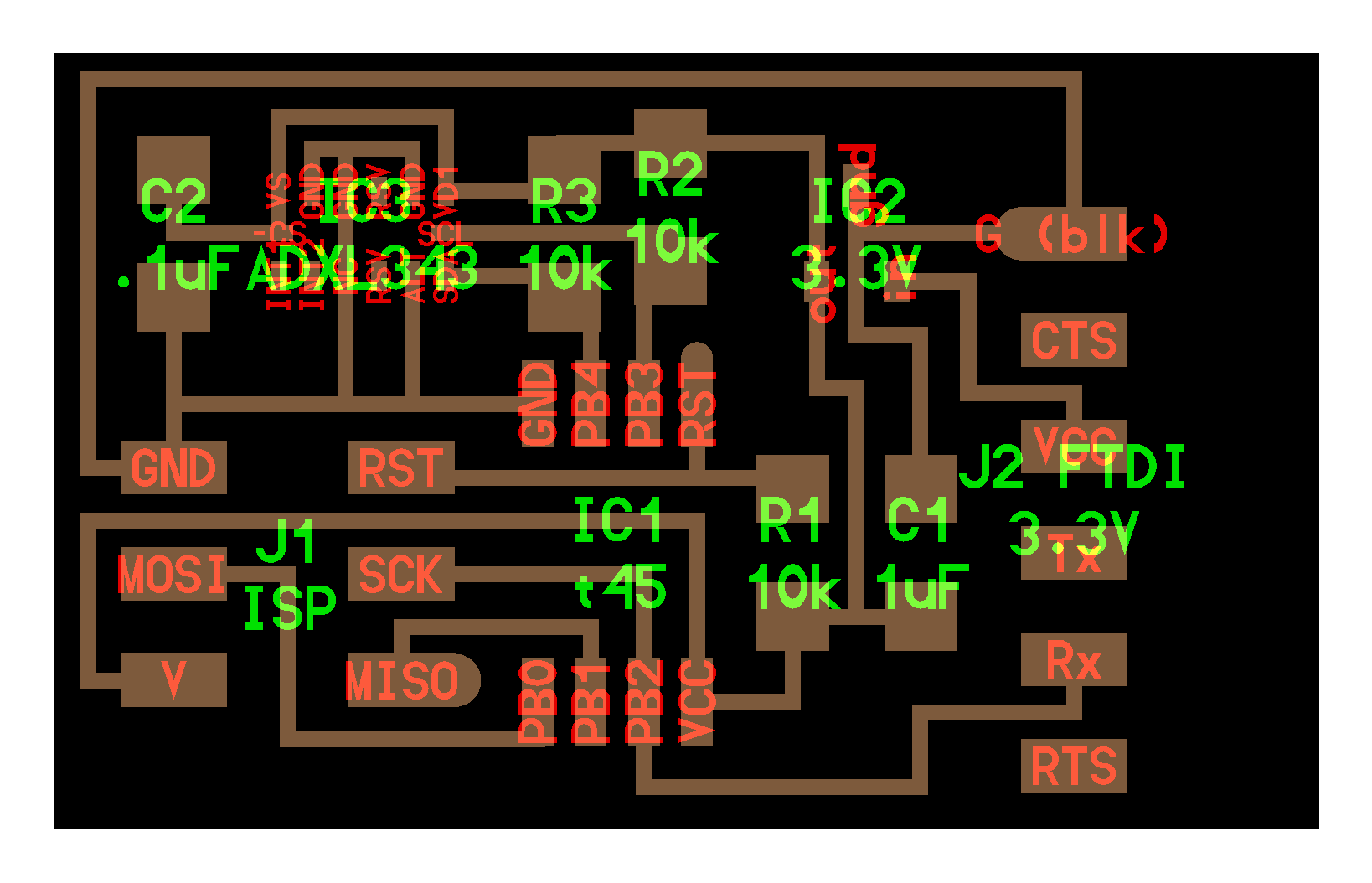
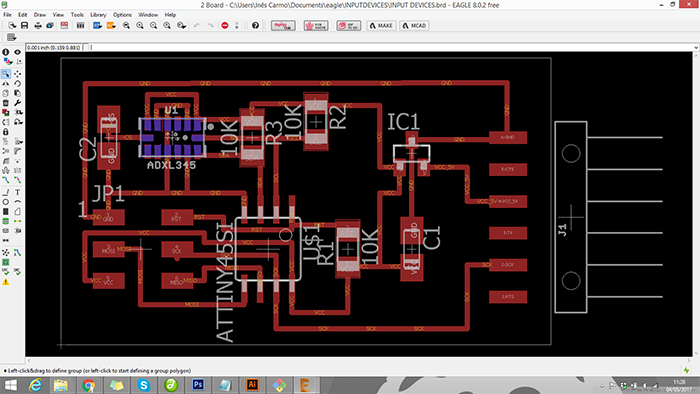
Board :
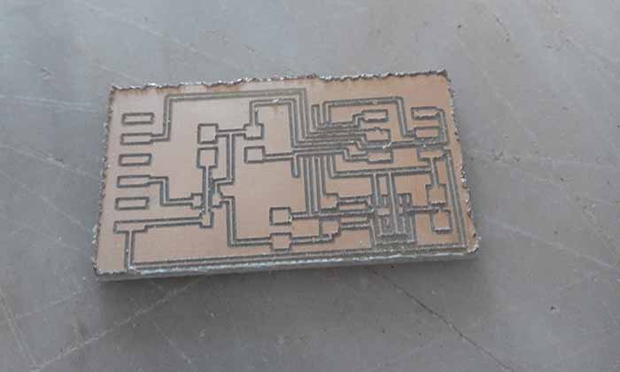
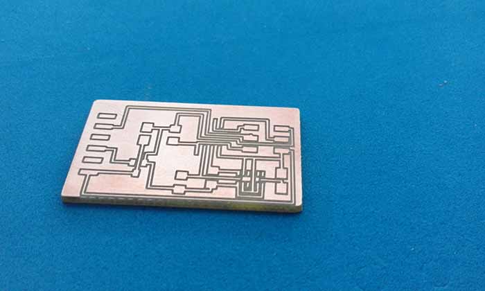
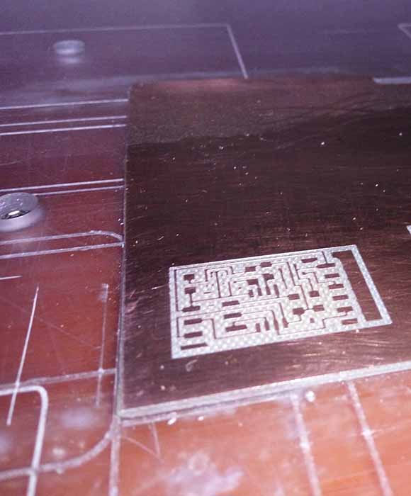
Making the Board
Same process as making boards in the recent weeks.
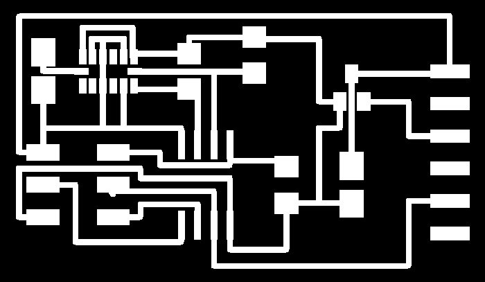
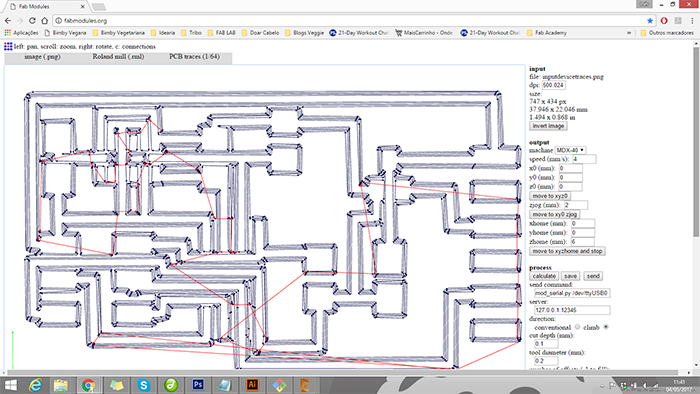
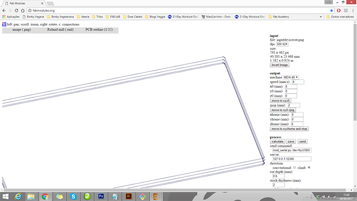
Png images:

Fabmodules:
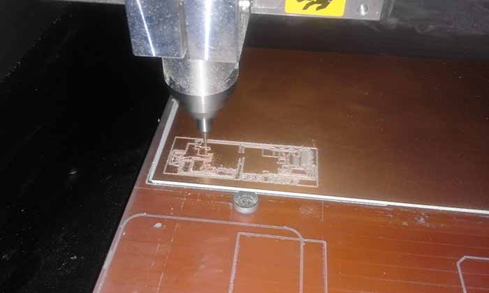
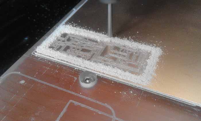
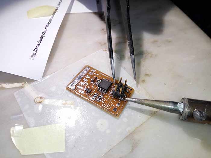
Milling and soldering:
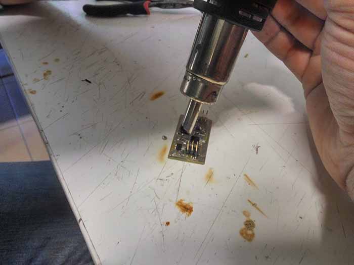
Soldering this board was a real challenge! I've being doing electronics for a just a few weeks.
And I wanted to use a tiny accelerometer for my project?! I'm starting to think that I must be crazy!
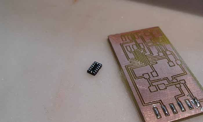
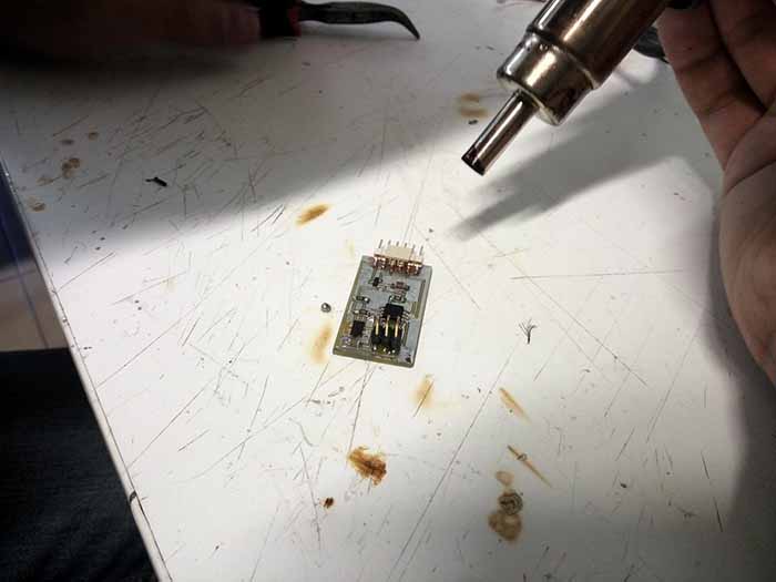
And to my surprise, it went really well I used a Hot-air Rework Station. And followed some tips like:
-
Set the temp and air-flow to the appropriate settings (slightly higher than the melting point of the solder,
and not too much air to blow your parts away). -
Wait for the hot-air station to warm up before using it.
-
Do not hot air on surfaces you don't want to get ruined.
-
Use tweezers to move or nudge parts while reworking. Hot-air is, well, hot.
-
By Sparkfun
Programing
First step, I burned the bootloader into the Attiny45
Then i uploaded Neil's code hello.ADXL343.c, and turned on the serial port to show the accelerometer data.
And besides baudrate values are the same, the data don't seem to be right as you can see in the video below.
2nd Try
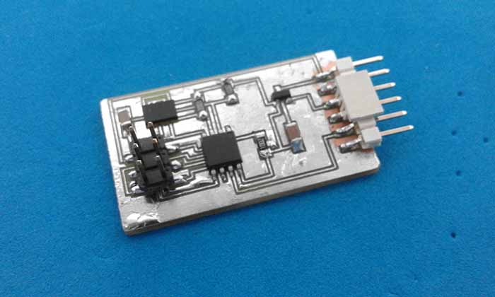
As my board was heating up the and the data was a little bit strange I decided to make another one
Milling:
Stuffing:
Programming:
At the second attempt I thought it would be better, but instead the accelerometer returned even stranger data.
As you can on the image see bellow:
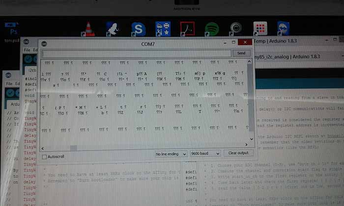
I think the problem might be the soldering of the accelerometer.
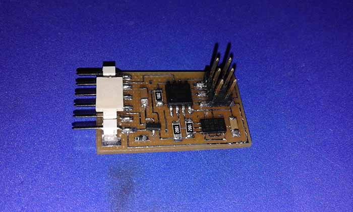
3rd Try
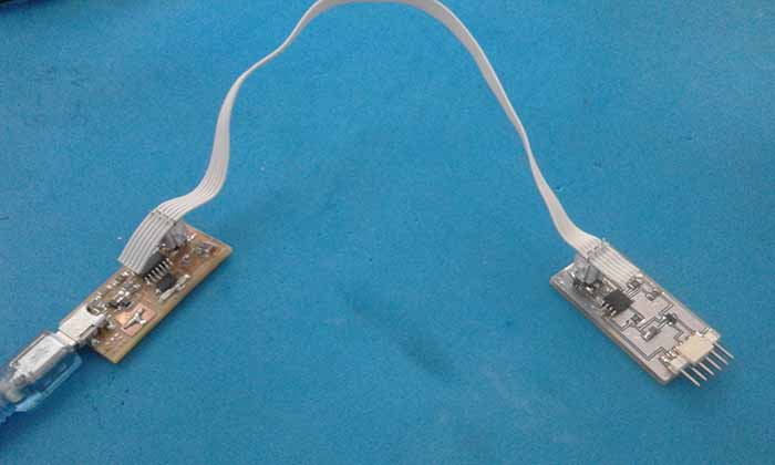
So, since I tried twice and did not get a different result, I'll try another way,
adapting the module that I used on my final project to a board that I have already from another assignment.
The board as the bridge from the Networking and Comunication because it has the ftdi connection and an
analog pin that is accessible
with minor modifications.
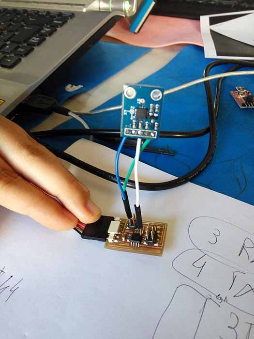
This is the final assembly, and the input result from this board are shown in pc.
In the video bellow you can see on the graph the changes of the acceleration y axis.