networking and communications
Week 15

networking and communications
Tasks
design and build a wired &/or wireless network connecting at least two processors
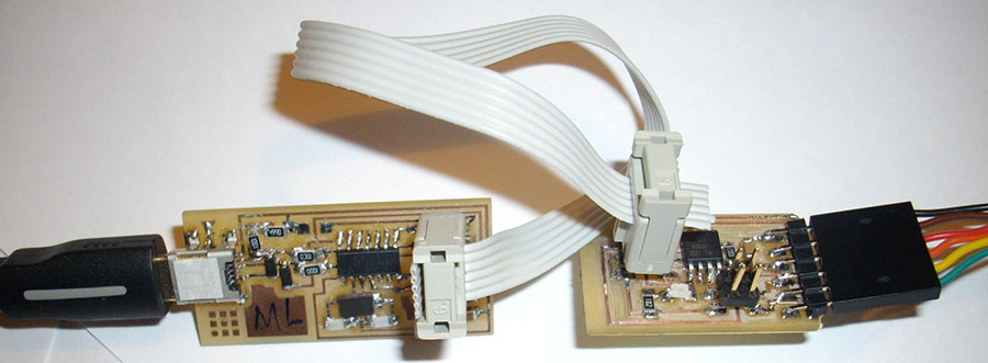
The boards
At the beginning I was expecting to make something with my microphone sensor, because it would be great to communicate between the nodes with this kind of input.
I saw an assignment that could help me. If I have the time, I’ll do it.
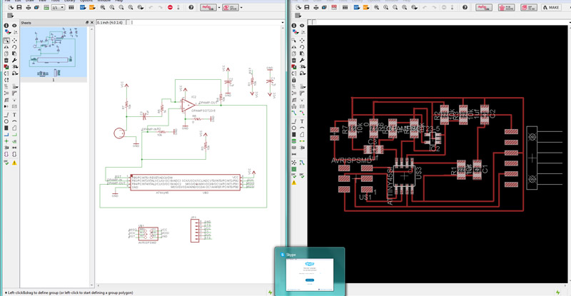
I draw the schematics of the bridge and the node in eagle and it was simplier than week 13 assignment. I knew what libraries to use and already begin to feel more confident about starting schematics from scratch.
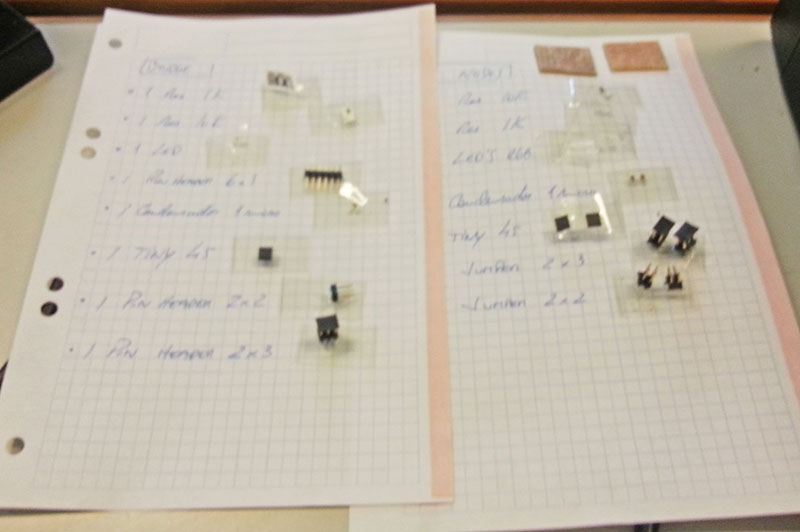
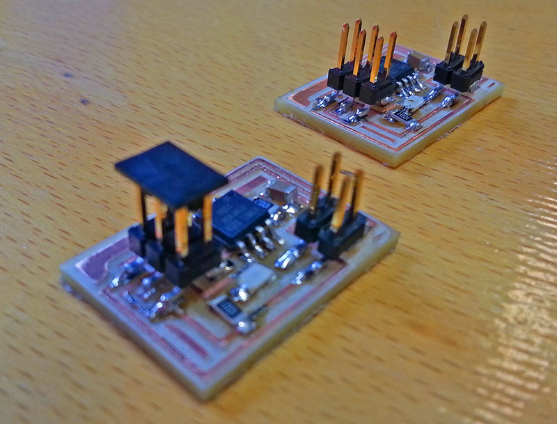
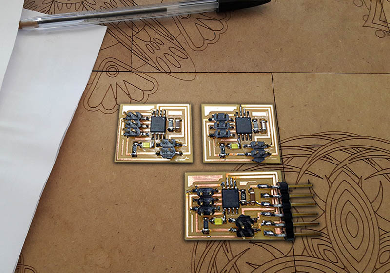
I exported the png files to mill and started collecting the components. Here are some pictures of the final boards:
Designing the board in Eagle
Preparing the components to the nodes and bridges
The node boards
All The boards
flashing the bridge
After having some problems on circuit welding and verifying everything again I milled again the the 2 nodes again, once the bridge was flashed ok. Everything seemed to work well then.
Programming
Download the files below (C and MAKE), put them in a folder and run this command in Terminal:
make -f hello.bus.45.make program-usbtiny
First program the bridge, and then the nodes.
When flashing the nodes, remember toc to modify the "hello.bus.45.c" code with the correspondent numbers (node 0 – 0; node 1 – 1; bridge – 2).
#define node_id '*'
ml@ubuntu:~/Desktop/Networking$ sudo make -f
hello.bus.45.make program-usbtiny
avr-objcopy -O ihex hello.bus.45.out hello.bus.45.c.hex;\
avr-size --mcu=attiny45 --format=avr hello.bus.45.out
AVR Memory Usage
----------------
Device: attiny45
Program: 796 bytes (19.4% Full)
(.text + .data + .bootloader)
Data: 4 bytes (1.6% Full)
(.data + .bss + .noinit)
avrdude -p t45 -P usb -c usbtiny -U flash:w:hello.bus.45.c.hex
avrdude: AVR device initialized and ready to accept instructions
Reading | ################################################## | 100% 0.01s
avrdude: Device signature = 0x1e9206
avrdude: NOTE: FLASH memory has been specified, an erase cycle will be performed
To disable this feature, specify the -D option.avrdude: erasing chip
avrdude: reading input file "hello.bus.45.c.hex"
avrdude: input file hello.bus.45.c.hex auto detected as Intel Hex
avrdude: writing flash (796 bytes):
Writing | ################################################## | 100% 1.00s
avrdude: 796 bytes of flash written
avrdude: verifying flash memory against hello.bus.45.c.hex:
avrdude: load data flash data from input file hello.bus.45.c.hex:
avrdude: input file hello.bus.45.c.hex auto detected as Intel Hex
avrdude: input file hello.bus.45.c.hex contains 796 bytes
avrdude: reading on-chip flash data:
Reading | ################################################## | 100% 0.72s
avrdude: verifying ...
avrdude: 796 bytes of flash verified
avrdude: safemode: Fuses OK
avrdude done. Thank you.
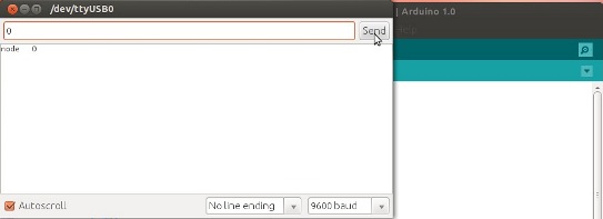
After programming, open the arduino IDE, set board and processor to Attiny45, run the program below open the Serial Monitor and the serial monitor, change the baud rate to 9600, type the number of the node you want to communicate, and pressed ENTER.
Arduino Serial Monitor communication
Arduino Program
#include <SoftwareSerial.h>
const int rx=0;
const int tx=1;
SoftwareSerial mySerial(rx,tx);
void setup() // run once, when the sketch starts
{
pinMode(7, OUTPUT);
digitalWrite(7, LOW);
mySerial.begin(9600); // set up Serial library at 9600 bps
}
void loop() // run over and over again
{
if(mySerial.available()>0)
{
char letter = mySerial.read();
if(letter == '1')
{
digitalWrite(7, HIGH);
mySerial.println("NODE 1");
}
else if(letter == '0')
{
digitalWrite(7, LOW);
mySerial.println("node 0");
}
}
// do nothing!
}
See the final result:
Video of the boards communicating
Eagle, png's and milling files