
Embedded Programming
Week 8: Assignment
This week's assignment is to read a microcontroller Data Sheet and program my echo hello world board to do something, with as many different programming languages and programming environments as possible. The data sheet which I referred was the Amtel 8-bit Microcontroller with 2K/4K/8K Bytes In-System Programmable Flash data sheet. This is the same data sheet as the ATtiny 44A used on my board.
Programming The Board
I have used following three languages to program my board.
- C using avr-gcc libraries.
From the C-source code the avr GCC compiler (together with the Preprocessor directives and the linker) produces machine code for the AVR microcontroller. Usually this code is used in the Intel Hex format pronounced (“Hexfile”). Download avr GCC compiler and avr library. This is available free for almost all platforms and operating systems. For Ms-Windows in the package WinAVR; for Unix/Linux AVR-GCC.
- C using Arduino IDE libraries.
Program written using Arduino IDE libraries takes most of the space of microcontroller because it loads many libraries of arduino into the chip. But this is the easiest to use. For writing code install Arduino IDE. Arduino 1.8.1 is the open source Arduino software (IDE) which makes easy to write code and upload it to the board. It runs on Windows, Mac OS X and Linux. The enviroment is written in Java and based on Processing and other open source software. This software can be used with any Arduino board.
- Assembly Language.
Assembly language is the alphanumeric representation of machine code. This language gives the maximum control. The space requirement for this is very less as there are no external libraries to load. The instructions used in writing programs in assembly language are not general but specific to the microcontroller. Each company provides a set of instructions for there microcontrollers.
Using the above mentioned languages, I have made the following programs:
- AVR C
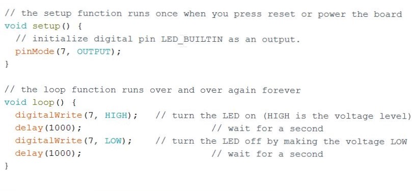
- Blink Program
- Button Blink Program
- Aurdino C
- Blink Program
- Button Blink Program
- Introduction of Assembly
Hardware Programmers, which can be used to program the board.
- ISP (In System Programmers)
In-system programming (ISP), also called In-Circuit Serial Programming (ICSP), is the ability of some programmable logic devices, microcontrollers, and other embedded devices to be programmed while installed in a complete system, rather than requiring the chip to be programmed prior to installing it into the system.
- Usbtiny44A or FabISP
The FabISP is an in-system programmer for AVR microcontrollers, designed for production within a FabLab. That is, it allows you to program the microcontrollers on other boards you make, using nothing but a USB cable and 6-pin IDC to 6-pin IDC cable. It's based on the USBtiny and V-USB firmwares, which allow the ATtiny44 to perform USB communication in software. Programming can be done through avrdude.
http://fab.cba.mit.edu/content/projects/fabisp/
- Arduino as ISP
The Arduino ISP is an In-System-Programmer that is used to program AVR microcontrollers. You can use the Arduino ISP to upload sketches directly on the AVR-based Arduino boards without the need of the bootloader. Otherwise you can use it to restore the bootloader.
https://www.arduino.cc/en/Tutorial/ArduinoISP
- Atmel ICE as Programmer.
The Atmel-ICE Debugger. Atmel-ICE is a powerful development tool for debugging and programming ARM® Cortex®-M based Atmel® SAM and Atmel AVR® microcontrollers with On-Chip Debug capability.
http://www.atmel.com/tools/atatmel-ice.aspx
Programming with AVR C
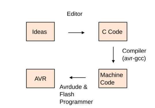
ToolChain
- Write your source code in an editor.
- Turn your source code into machine code with a compiler (and associated software tools).
- Using uploader software on your big computer and a hardware flash programmer, send the machine code to your target AVR chip, which stores the instructions in its nonvolatile flash memory.
- As soon as the flash programmer is done, the AVR chip resets and starts running your code.
Steps Followed
- Install all the softwares needed to program in C. Install avrdude, gcc-avr, binutils-avr, and avr-libr. The gcc-avr is the cross compiler collection. The avrdude is a command line program for reading, writing and manipulating AVRs. The binutils-avr provide the low level utilities needed in building and manipulating object files. The avr-libr files provide similar functions found in a standard C library for specifically the AVR. Needless to say, all of these files are essential in programming the ATTiny44. Following link can be reffered to know the command line for the installation of afore said files in Linux.
http://maxembedded.com/2015/06/setting-up-avr-gcc-toolchain-on-linux-and-mac-os-x/
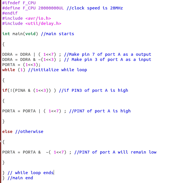
- Download make file and write your c program for blinking Led in gedit.
Download Make File
Down C program for blinking the Led
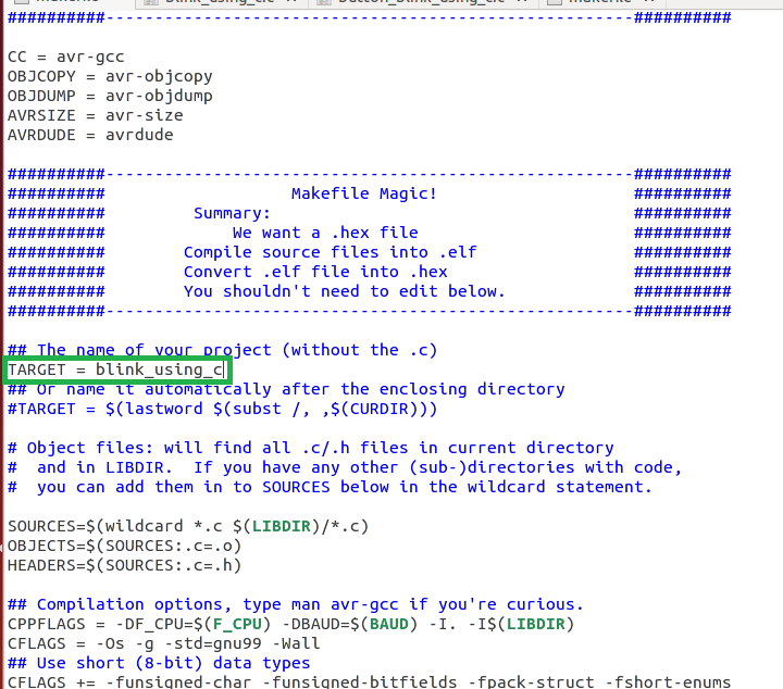
- Save both your .c file and make file in the same folder and change the Target of the name of your project in make file, as shown below.
- Within the folder, where you have saved your both .c file and make file. Open in terminal and used the command line (sudo make flash).
What is make file
Compiling the source code files can be tiring, especially when you have to include several source files and type the compiling command every time you need to compile. Makefiles are the solution to simplify this task. Makefiles are special format files that help build and manage the projects automatically. The make command allows you to manage large programs or groups of programs. As you begin to write large programs, you notice that re-compiling large programs takes longer time than re-compiling short programs. Moreover, you notice that you usually only work on a small section of the program ( such as a single function ), and much of the remaining program is unchanged. Makefile is a program building tool which runs on Unix, Linux, and their flavors. It aids in simplifying building program executables that may need various modules. Once you’ve compiled your C code into machine code in the right format, it’s time to send the machine code over to the chip and write it into nonvolatile flash memory (We will be using FabISP).
C Program for blinking Led

C Program for blinking Led using Button
Follow the same procedure as done for blinking the Led.
 Down C program for blinking the Led using Button
Programming with Arduino C
Steps
- Download Arduino.
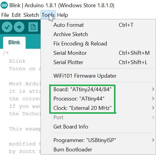
- Do the required settings, as shown below.
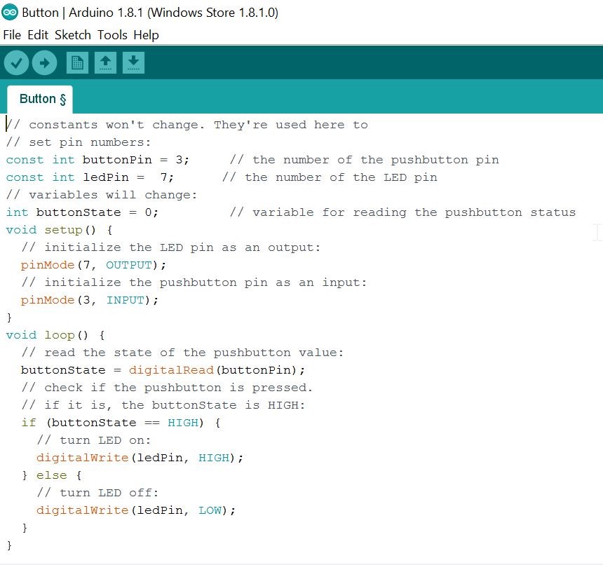
- Main advantage of using Arduino is that, you will find basic sample programs in File>>Examples. Therofore, I used the example for blinking the Led and did the required manipulations as shown below.
Programming with Assembly
I referred following links to understand assembly language. I got a basic idea about assembly language but it was not sufficient to write any program.
https://www.tutorialspoint.com/assembly_programming/assembly_environment_setup.htm
https://www.youtube.com/watch?v=ViNnfoE56V8
Comparision
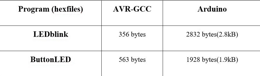
Since, this was my first exposure to embedded programming. I found arduino simple in comparision to C. But, the program sizes of arduino are comparitively very big as comparision to C.
ATtiny44 Datasheet Review
This datasheet covers ATtiny24 / 44 / 84. We're using ATtiny44.
While going through the datasheet first time, it was chinees for me. So, with help of my local instructor and fellow companions, I tried to understand certain things. One thing I want to mention is that, datasheet is not a step by step manual. It is something, which tells you the properties of various microcontrollers and help you predit their behaviour and to master it, it requires dedicated efforts and time. I have made following notes as breif introduction to certain important terms, which might to help to understand datasheet in much appropriate manner.
- Key features
- RISC - Mostly single clock cycle Execution
- Speed - upto 20mhz at 4.5 - 5.5 V (upto 10mhz at 2.7 - 4.5 V)
- Low power mode
- 32 8bit registers
- 4K In-System, Self programmable Flash Program Memory
- 256 Bytes SRAM
- Memory
- Separate data and program memory, also EEPROM for data storage.
- 4k program memory for tiny44 - 2k x 16 bytes locations (1 instructions takes 16 / 32b)
- SRAM first 32b for register file next 64b for IO registers next 256b for data access time is 2 clock cycles: 1 to compute address, 1 to access
- EEPROM 256b
- Fuse bytes
- 3 bytes of non-volatile memory
- Bits to control important settings like clock source, debugWire enable, etc
- Status Register
- updated after every instruction
- bit 7 - Global Interrupt Enable bit
- It is cleared by hardware when an interrupt occurs, is set by RETI instruction to enable subsequent interrupts
- Register File
- 32 general purpose registers
- Also have an address as the first 32 locations of user data space
- Stack pointer
- Separate stacks for subroutines and interrupts
- Instruction execution timing
- Within 1 clock cycle: fetch 2 register operands, execute ALU operation, store result into register
- Reset & Interrupt handling
- Interrupt vector stored in program space
- Interrupts have priorities - RESET has highest, next is INT0 - External Interrupt Request 0
- Takes 4 clock cycles to start executing interrupt routine code, and 4 to return from it
- Clock
- Multiple clock sources possible
- External
- Internal 8mhz
- Default source with prescaling to 1mhz
- Internal 128khz
- Internal 32khz
- Multiplexer selects one based on fuse set
- This is passed through a prescaler, which divides the clock source to reduce power consumption
- This 'system' clock feeds into AVR Clock Control Unit, which provides different clock domains - CPU, IO, ADC, Flash
- System clock output can be sent to the CKOUT pin by setting a fuse
- Power Management and Sleep Modes
- 4 sleep modes: idle, ADC noise reduction, power-down, stand by
- Reset
- 4 sources:
- Power On Reset:
- External reset: low value on the RESET pin
- BOD reset: triggered when voltage drops below a threshold
- Watchdog timer: triggered when timer fires
- Watchdog Timer
- Generates a reset pulse when a given delay is exceeded, and a WDR (Watchdog Reset) instruction has not been executed
- IO
- Pins can be marked as input or output using DDRxn bit, input is 0, output is 1
- Pull-up resistor can be enabled on input pins by setting PORTxn to 1
- 8bit / 16bit Timer/Counter with PWM
- Can be used to time program execution, waveform generation
- Analog Comparator
- Can monitor voltages on AIN0 (postive) and AIN1(negative) and trigger an interrupt or output a value when the positive voltage is higher than the negative one
- DebugWire
- Bi-directional interface to control program flow, execute instructions and program non-volatile memories
- Uses RESET port pin
- Self Programming Mechanism for Flash
- Allows MCU to download and upload code using any data interface and write to program flash memory
Future Learning
Would love to work on some more projects of embedded.
Question
Reset and Interrupt Handling ? (Page 12 of datasheet)
From the C-source code the avr GCC compiler (together with the Preprocessor directives and the linker) produces machine code for the AVR microcontroller. Usually this code is used in the Intel Hex format pronounced (“Hexfile”). Download avr GCC compiler and avr library. This is available free for almost all platforms and operating systems. For Ms-Windows in the package WinAVR; for Unix/Linux AVR-GCC.
Program written using Arduino IDE libraries takes most of the space of microcontroller because it loads many libraries of arduino into the chip. But this is the easiest to use. For writing code install Arduino IDE. Arduino 1.8.1 is the open source Arduino software (IDE) which makes easy to write code and upload it to the board. It runs on Windows, Mac OS X and Linux. The enviroment is written in Java and based on Processing and other open source software. This software can be used with any Arduino board.
Assembly language is the alphanumeric representation of machine code. This language gives the maximum control. The space requirement for this is very less as there are no external libraries to load. The instructions used in writing programs in assembly language are not general but specific to the microcontroller. Each company provides a set of instructions for there microcontrollers.
- AVR C
- Blink Program
- Button Blink Program
- Aurdino C
- Blink Program
- Button Blink Program
- Introduction of Assembly
- ISP (In System Programmers)
- Usbtiny44A or FabISP
- Arduino as ISP
- Atmel ICE as Programmer.
In-system programming (ISP), also called In-Circuit Serial Programming (ICSP), is the ability of some programmable logic devices, microcontrollers, and other embedded devices to be programmed while installed in a complete system, rather than requiring the chip to be programmed prior to installing it into the system.
The FabISP is an in-system programmer for AVR microcontrollers, designed for production within a FabLab. That is, it allows you to program the microcontrollers on other boards you make, using nothing but a USB cable and 6-pin IDC to 6-pin IDC cable. It's based on the USBtiny and V-USB firmwares, which allow the ATtiny44 to perform USB communication in software. Programming can be done through avrdude.
http://fab.cba.mit.edu/content/projects/fabisp/The Arduino ISP is an In-System-Programmer that is used to program AVR microcontrollers. You can use the Arduino ISP to upload sketches directly on the AVR-based Arduino boards without the need of the bootloader. Otherwise you can use it to restore the bootloader.
https://www.arduino.cc/en/Tutorial/ArduinoISPThe Atmel-ICE Debugger. Atmel-ICE is a powerful development tool for debugging and programming ARM® Cortex®-M based Atmel® SAM and Atmel AVR® microcontrollers with On-Chip Debug capability.
http://www.atmel.com/tools/atatmel-ice.aspx- Write your source code in an editor.
- Turn your source code into machine code with a compiler (and associated software tools).
- Using uploader software on your big computer and a hardware flash programmer, send the machine code to your target AVR chip, which stores the instructions in its nonvolatile flash memory.
- As soon as the flash programmer is done, the AVR chip resets and starts running your code.
- Install all the softwares needed to program in C. Install avrdude, gcc-avr, binutils-avr, and avr-libr. The gcc-avr is the cross compiler collection. The avrdude is a command line program for reading, writing and manipulating AVRs. The binutils-avr provide the low level utilities needed in building and manipulating object files. The avr-libr files provide similar functions found in a standard C library for specifically the AVR. Needless to say, all of these files are essential in programming the ATTiny44. Following link can be reffered to know the command line for the installation of afore said files in Linux. http://maxembedded.com/2015/06/setting-up-avr-gcc-toolchain-on-linux-and-mac-os-x/
- Download make file and write your c program for blinking Led in gedit. Download Make File Down C program for blinking the Led
- Save both your .c file and make file in the same folder and change the Target of the name of your project in make file, as shown below.
- Within the folder, where you have saved your both .c file and make file. Open in terminal and used the command line (sudo make flash).
What is make file
Compiling the source code files can be tiring, especially when you have to include several source files and type the compiling command every time you need to compile. Makefiles are the solution to simplify this task. Makefiles are special format files that help build and manage the projects automatically. The make command allows you to manage large programs or groups of programs. As you begin to write large programs, you notice that re-compiling large programs takes longer time than re-compiling short programs. Moreover, you notice that you usually only work on a small section of the program ( such as a single function ), and much of the remaining program is unchanged. Makefile is a program building tool which runs on Unix, Linux, and their flavors. It aids in simplifying building program executables that may need various modules. Once you’ve compiled your C code into machine code in the right format, it’s time to send the machine code over to the chip and write it into nonvolatile flash memory (We will be using FabISP).
Down C program for blinking the Led using Button
- Download Arduino.
- Do the required settings, as shown below.
- Main advantage of using Arduino is that, you will find basic sample programs in File>>Examples. Therofore, I used the example for blinking the Led and did the required manipulations as shown below.
- Key features
- RISC - Mostly single clock cycle Execution
- Speed - upto 20mhz at 4.5 - 5.5 V (upto 10mhz at 2.7 - 4.5 V)
- Low power mode
- 32 8bit registers
- 4K In-System, Self programmable Flash Program Memory
- 256 Bytes SRAM
- Memory
- Separate data and program memory, also EEPROM for data storage.
- 4k program memory for tiny44 - 2k x 16 bytes locations (1 instructions takes 16 / 32b)
- SRAM first 32b for register file next 64b for IO registers next 256b for data access time is 2 clock cycles: 1 to compute address, 1 to access
- EEPROM 256b
- Fuse bytes
- 3 bytes of non-volatile memory
- Bits to control important settings like clock source, debugWire enable, etc
- Status Register
- updated after every instruction
- bit 7 - Global Interrupt Enable bit
- It is cleared by hardware when an interrupt occurs, is set by RETI instruction to enable subsequent interrupts
- Register File
- 32 general purpose registers
- Also have an address as the first 32 locations of user data space
- Stack pointer
- Separate stacks for subroutines and interrupts
- Instruction execution timing
- Within 1 clock cycle: fetch 2 register operands, execute ALU operation, store result into register
- Reset & Interrupt handling
- Interrupt vector stored in program space
- Interrupts have priorities - RESET has highest, next is INT0 - External Interrupt Request 0
- Takes 4 clock cycles to start executing interrupt routine code, and 4 to return from it
- Clock
- Multiple clock sources possible
- External
- Internal 8mhz
- Default source with prescaling to 1mhz
- Internal 128khz
- Internal 32khz
- Multiplexer selects one based on fuse set
- This is passed through a prescaler, which divides the clock source to reduce power consumption
- This 'system' clock feeds into AVR Clock Control Unit, which provides different clock domains - CPU, IO, ADC, Flash
- System clock output can be sent to the CKOUT pin by setting a fuse
- Power Management and Sleep Modes
- 4 sleep modes: idle, ADC noise reduction, power-down, stand by
- Reset
- 4 sources:
- Power On Reset:
- External reset: low value on the RESET pin
- BOD reset: triggered when voltage drops below a threshold
- Watchdog timer: triggered when timer fires
- Watchdog Timer
- Generates a reset pulse when a given delay is exceeded, and a WDR (Watchdog Reset) instruction has not been executed
- IO
- Pins can be marked as input or output using DDRxn bit, input is 0, output is 1
- Pull-up resistor can be enabled on input pins by setting PORTxn to 1
- 8bit / 16bit Timer/Counter with PWM
- Can be used to time program execution, waveform generation
- Analog Comparator
- Can monitor voltages on AIN0 (postive) and AIN1(negative) and trigger an interrupt or output a value when the positive voltage is higher than the negative one
- DebugWire
- Bi-directional interface to control program flow, execute instructions and program non-volatile memories
- Uses RESET port pin
- Self Programming Mechanism for Flash
- Allows MCU to download and upload code using any data interface and write to program flash memory