
Group Page
Week 9 & Week 11: Assignment
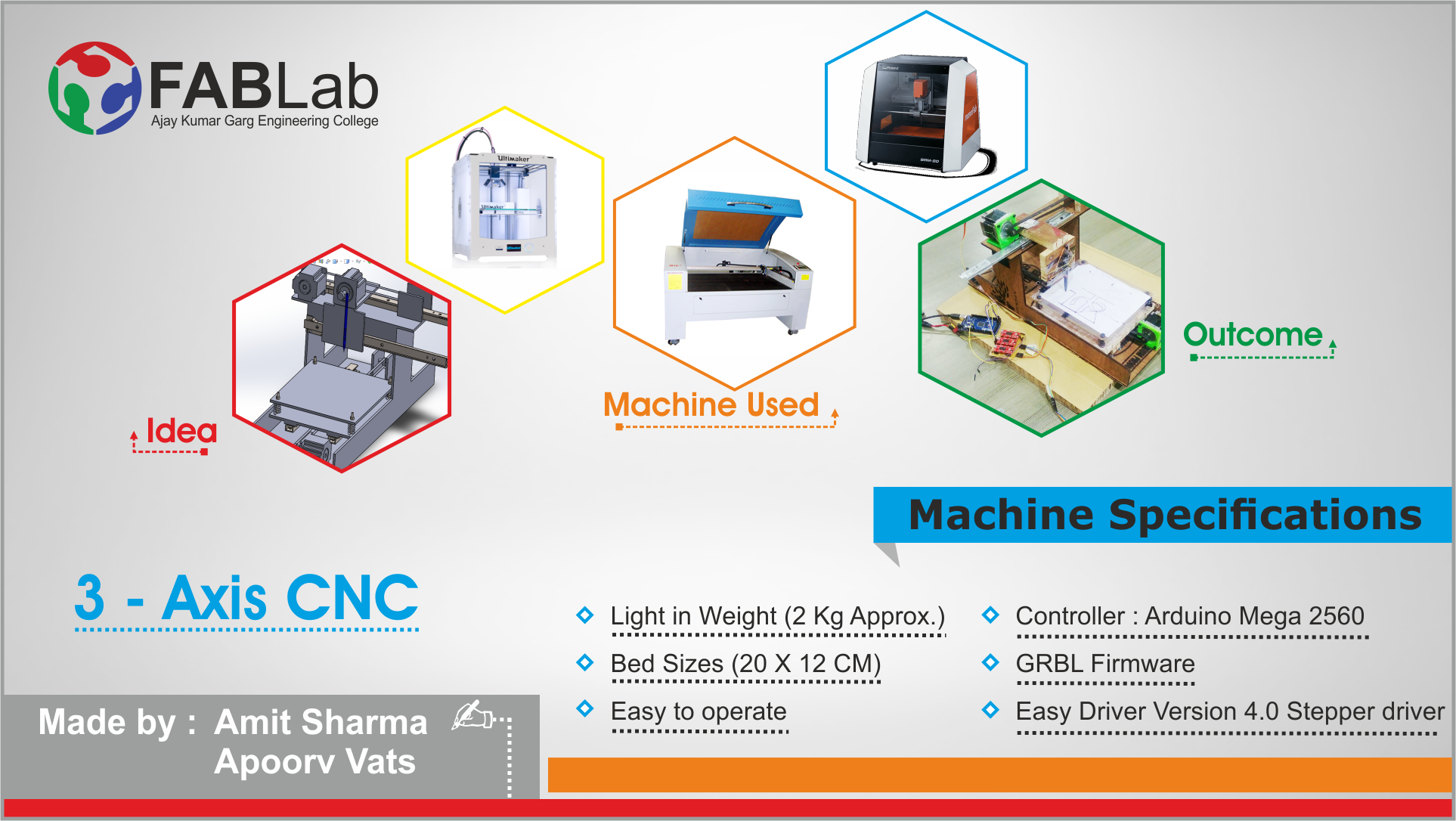
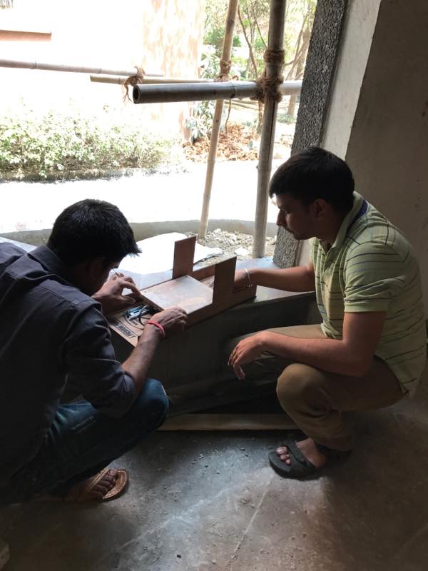
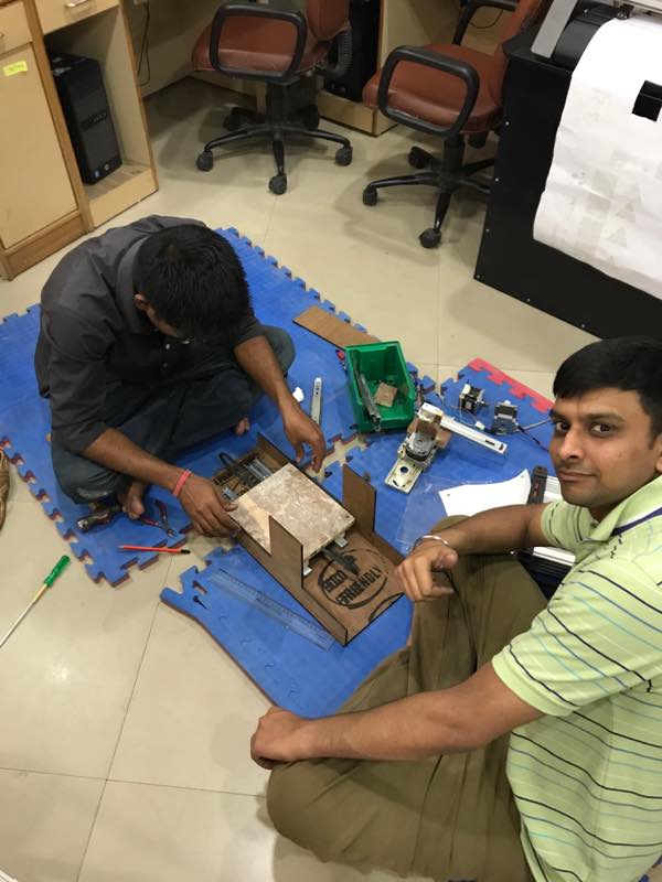
This week's assignment is to make a machine in group and test it by operating manually and afterwards automate it. Since, we are only two people, who are undergoing this FabAcademy Course in our AKGEC FabLab, India. So, me (Amit Sharma) and Apoorv Vats started with the task in hand. We needed to document the group project and my individual contribution.
Poster
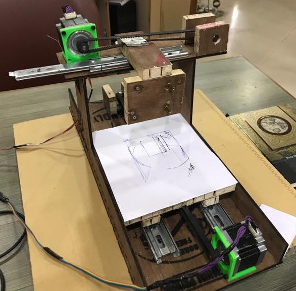
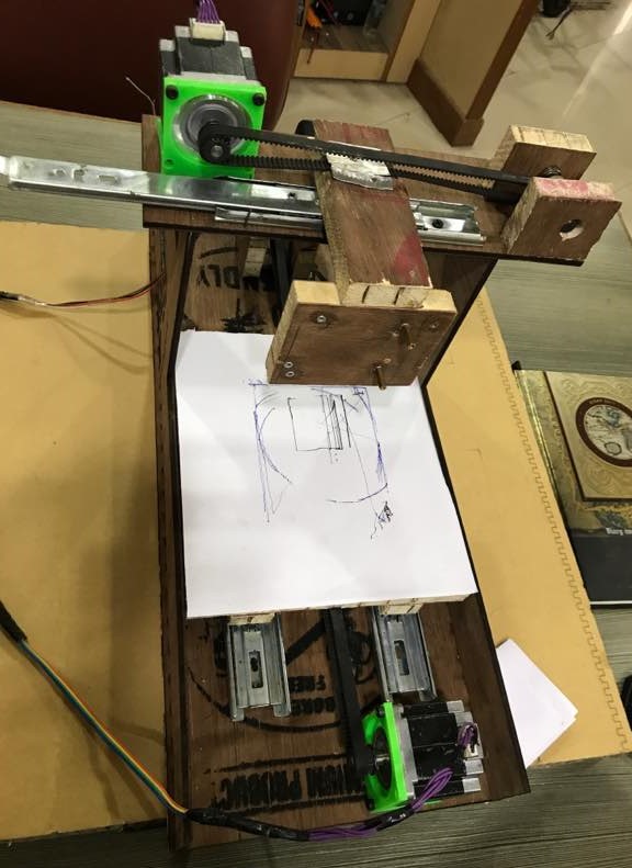
Machine in Action
Poster
Presentation slide
Machine in Action
Presentation videoTeam Members
Brainstorming
After the lecture on Mechanical Design, next day we met as a group for brainstorming session and discussed various projects which can me made as our group project. We took some inspiration from the lecture "Machines that Makes Machines" and have also gone through various Youtube tutorials before finalizing our project. We looked at many of the previous year designs to draw inspiration. Our debate centered upon making a thermocol cutting machine (2 axis CNC machine wire cutter), Automatic Drilling machine, Pneumatic flute. Many ideas were bantered around before we settled upon making a 3 axis CNC Router. We also included our local instructor and one Prof. from Mechanical Engineering Department in brainstorming sessions, to get benefited from their vast experience and knowledge.
Work Distribution
Immediately after the finalization of the project, we distributed the work among ourselves as follow: I started working on designing and fabrication of the machine and Apoorv started working on the electrical aspect of the project. i.e. How motors will be derived, making of PCB board and how gcodes will be dumped to make the motor move accordingly.
Amit Sharma's Contribution
Mechanical Design
Step 1
After deciding the machine, we looked upon the inventory of our lab to check the availability of the components and accordingly finalizing it for the machine building.
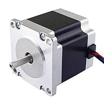
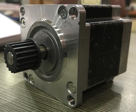
Stepper Motor
NEMA 23 is available in our lab and therefore, we used these 3 motors for providing X, Y, & Z motions. NEMA 23 has 200 steps to one revolution (1.8 degrees per step). It has 4 coils and can be wired both as bipolar and unipolar, but we joined the wires to turn it to bipolar motors.
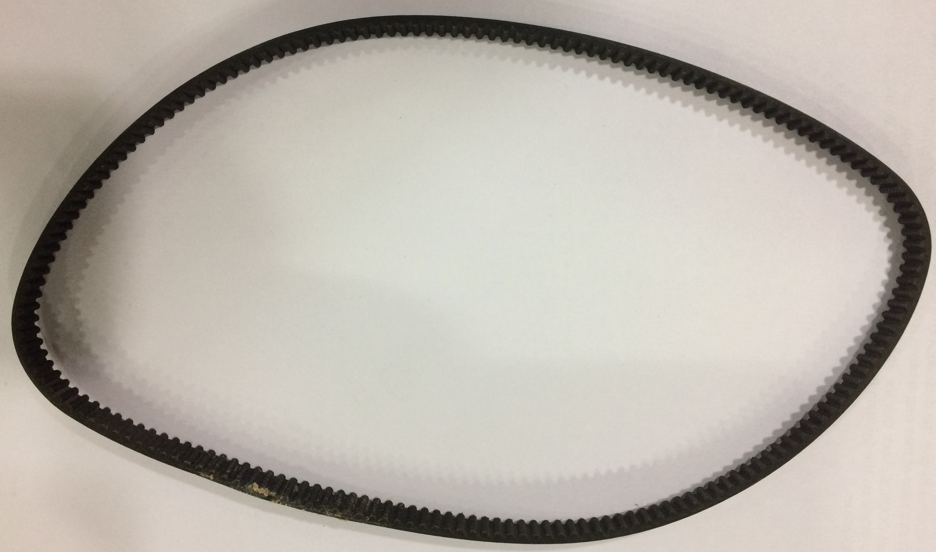
Timing Belt
|
 |
Linear Slide
For linear movement along the axis, telescopic linear slides is being used, as shown in figure |
 |
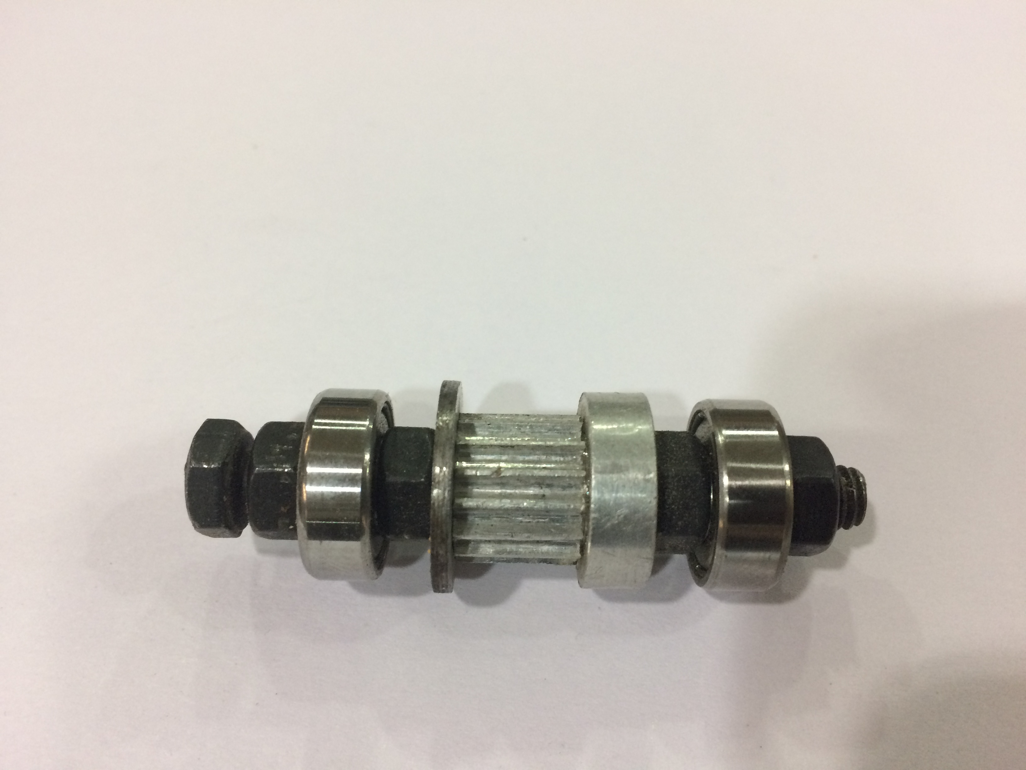
Pulley and Ball Bearings
Step 2
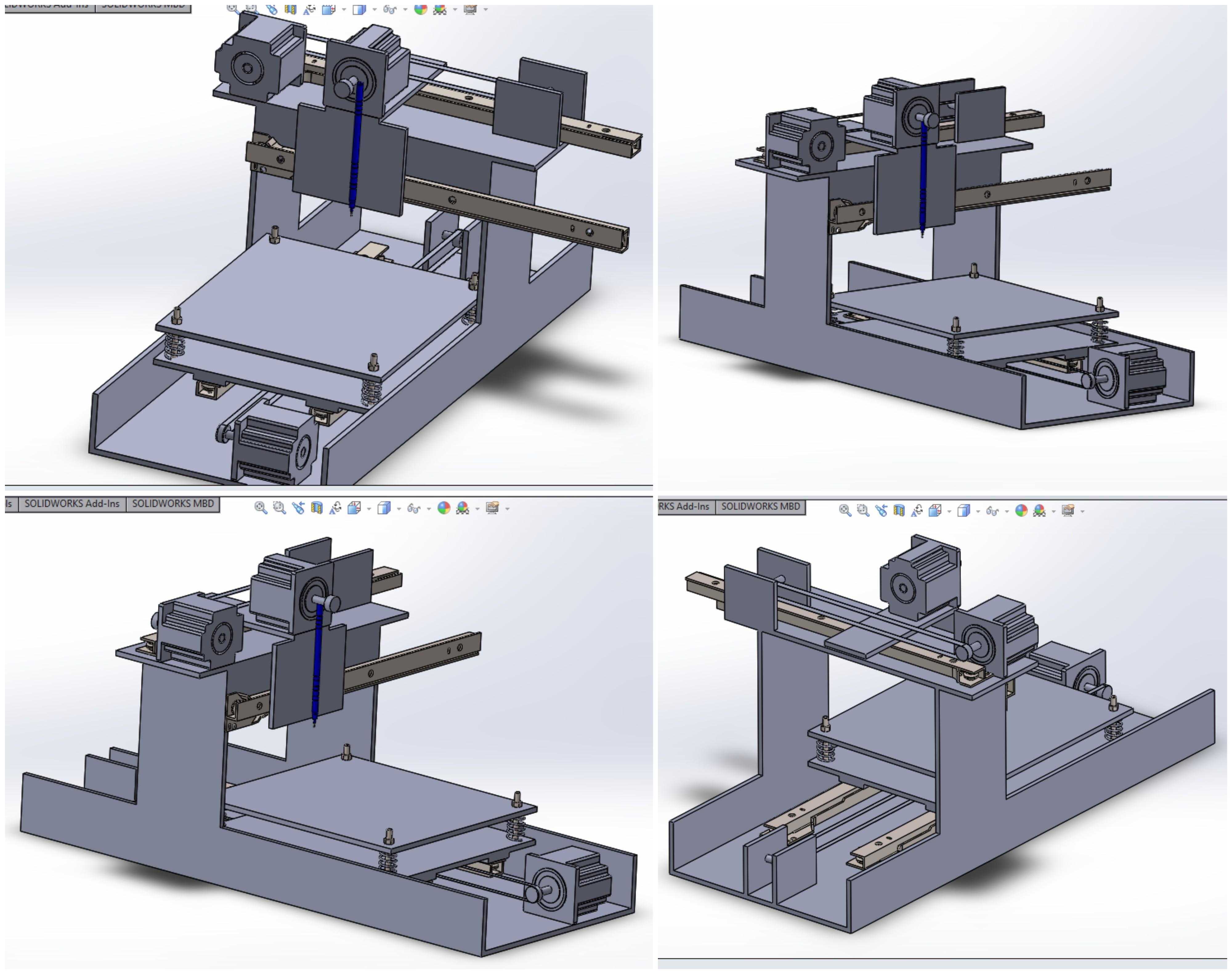
After checking all the available inventory, I got a pretty good idea that how my designing is going to be. So, I created a solidworks model for my machine. I created various parts and then assembled them. Various parts file and assembly can be downloaded from the link below. While making the machine, I faced certain problems, which I didn't thought of while making 3D model. So, did some manipulations in my design as per the requirements. Those problems is being discussed, in Machine Design section.
Downloads
Machine Designing
Apoorv Vats's Contribution
Stepper Motor
NEMA 23
It has 200 steps to ne revolution (1.8 degree per step). It actually has 4 coils (which means it can be wired as both a bipolar and unipolar), but we join wires to turn it into a bipolar.
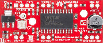
EasyDriver - Stepper Motor Driver
To drive the stepper motor we decided to use Easy Stepper Motor Driver.
Quick Pin Description:
Please see the Allego A3967 data sheet linked above for complete technical details. The Easy Driver is basically just a breakout board for this driver chip, so the datasheet is your best source of information about how it all works. However, if all you need is a reference to the pins, here you go:
- GND : There are three GND (Ground) pins on the Easy Driver. They are all connected together inside the board. Connect the negative side of your power supply, as well as from any other boards you are using to drive the Easy Driver to one or more of the GND pins.
- M+ : This is the power input to the Easy Driver. Connect this to the positive power supply lead. This should be a 6V to 30V, 2A (or more) power supply that is clean (low ripple).
- A and B : (four pins) These are the motor connections. See below diagrams for how to hook these up. A and B are the two coils of the motor, and can swap the two wires for a given coil (it will just reverse the direction of the motor). Make CERTAIN that this connection to the motor is solid, and NOT through a connector that has any chance of intermittent contact (which will fry the motor driver chip).
- STEP : This needs to be a 0V to 5V (or 0V to 3.3V if you've set your Easy Driver that way) digital signal. Each rising edge of this signal will cause one step (or microstep) to be taken.
- DIR (Direction) : This needs to be a 0V to 5V (or 0V to 3.3V if you've set your Easy Driver up that way) digital signal. The level if this signal (high/low) is sampled on each rising edge of STEP to determine which direction to take the step (or microstep).
- That's it - those are the only signals that you absolutely need to connect to anything. All the rest below are optional - in other words, the Easy Driver sets them to reasonable default values.
- MS1/MS2 : These digital inputs control the microstepping mode. Possible settings are (MS1/MS2) : full step (0,0), half step (1,0), 1/4 step (0,1), and 1/8 step (1,1 : default).
- RST (reset) : This normally high input signal will reset the internal translator and disable all output drivers when pulled low.
- SLP (sleep) : This normally high input signal will minimize power consumption by disabling internal circuitry and the output drivers when pulled low.
- ENABLE : This normally low input signal will disable all outputs when pulled high.
Description:
The EasyDriver is a simple to use stepper motor driver, compatible with anything that can output a digital 0 to 5V pulse (or 0 to 3.3V pulse if you solder SJ2 closed on the EasyDriver). The EasyDriver requires a 6V to 30V supply to power the motor and can power any voltage of stepper motor. The EasyDriver has an on board voltage regulator for the digital interface that can be set to 5V or 3.3V. Connect a 4-wire stepper motor and a microcontroller and you’ve got precision motor control! EasyDriver drives bi-polar motors, and motors wired as bi-polar. I.e. 4,6, or 8 wire stepper motors.
Features:
- A3967 Microstepping Driver
- MS1 and MS2 pins broken out to change microstepping resolution to full, half, quarter and eighth steps (defaults to eighth).
- Compatible with 4, 6, and 8 wire stepper motors of any voltage.
- Adjustable current control from 150mA/phase to 700mA/phase.
- Power supply range from 6V to 30V. The higher the voltage, the higher the torque at high speeds.
Note: Do not connect or disconnect a motor while the driver is energized. This will cause permanent damage to the A3967 IC.
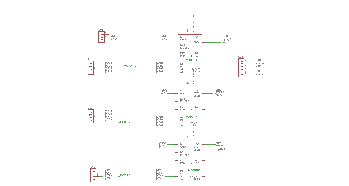
Schematic and Board
I used Eagle 7.7.0 to make the schematic and board. In schematic three Easy Stepper Motor driver is used to drive three motors at X,Y and Z axes. To add pin layout for drivers in eagle the library is downloaded from here. All the drivers will recieve 12 V suplly from common terminal. For Step and Direction of each motor 6 Pin male header is mounted on the board. Below is the snapshot of the Schematic.
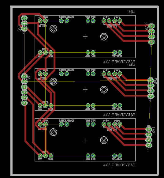
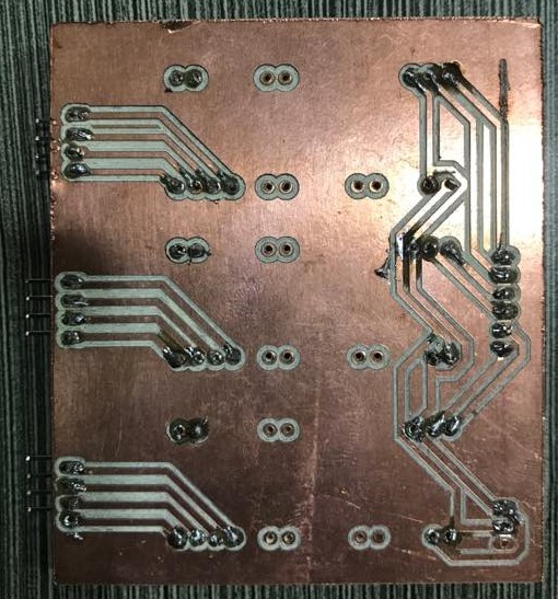
Board
While routing the board the mirror image of drivers is used as they need to be mounted on the bottom side of the board.
Download plotter.sch
plotter.brd
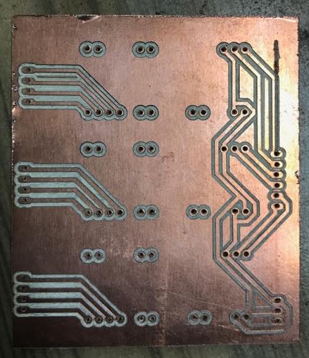
Milling the Board
For milling the board the toolpath is generated using the FabModules.
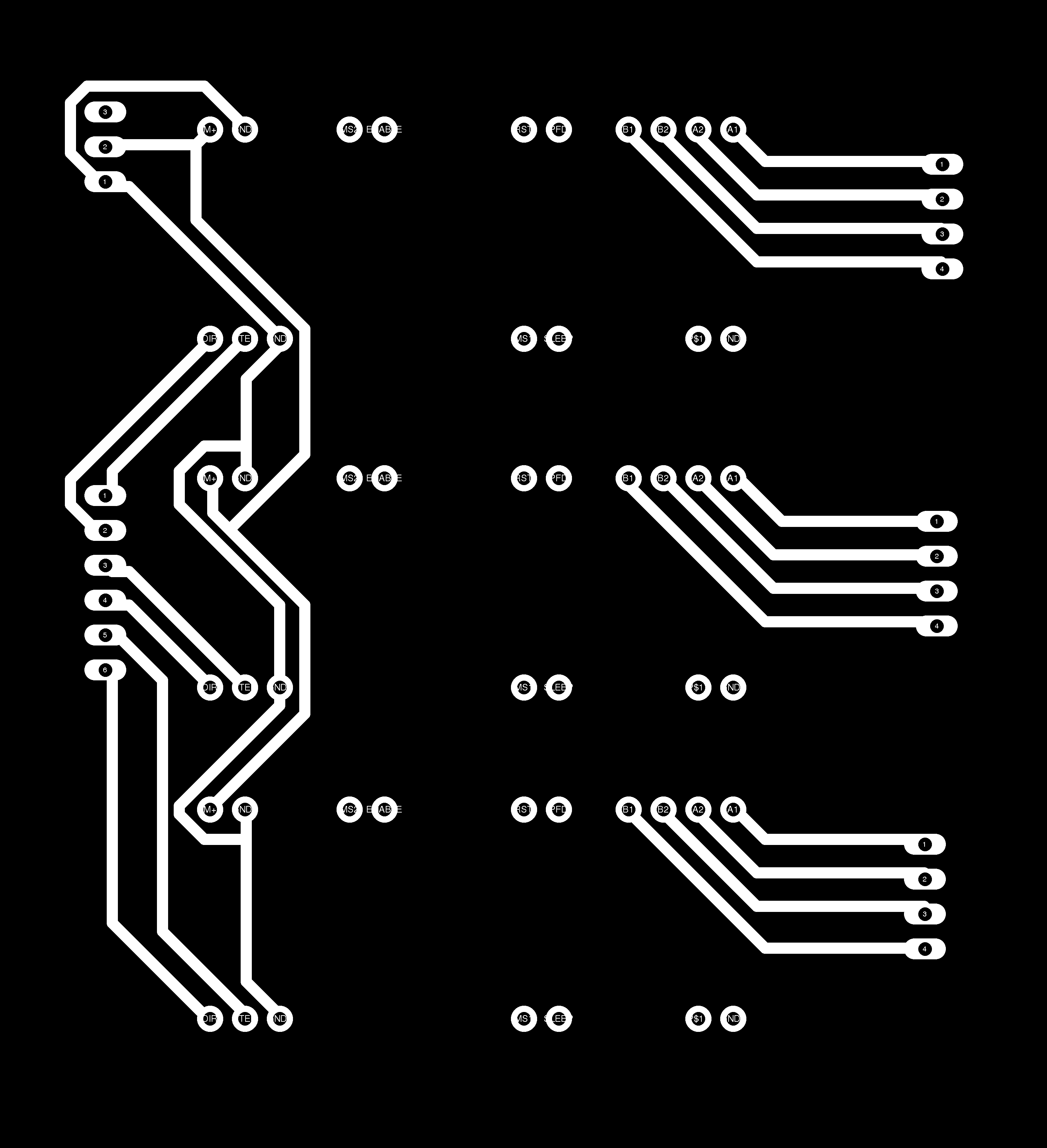

Download traces.png
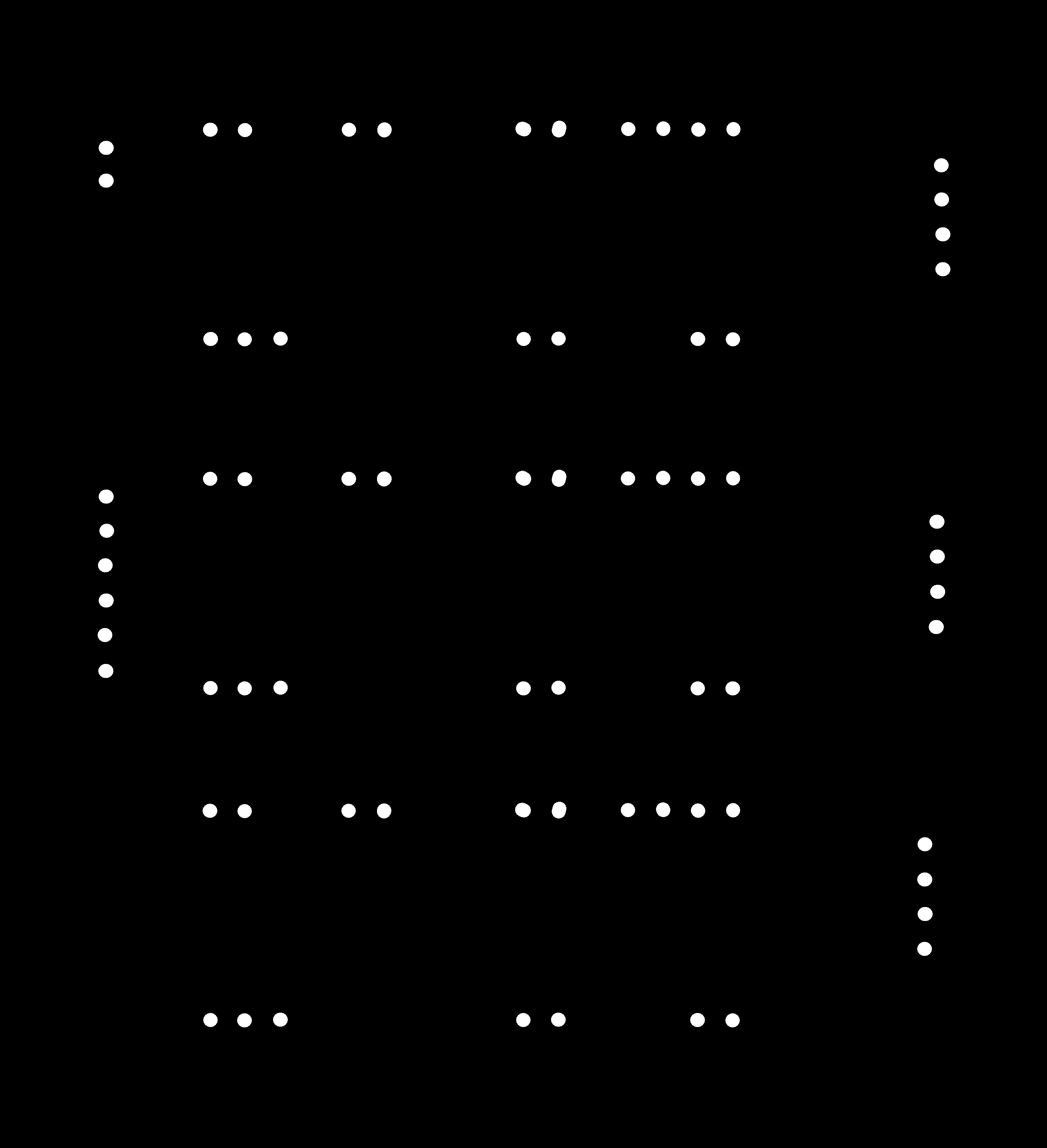
Download interior.png
Download holes.png
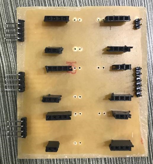
Milled Board
Soldering the Stuff
The problem which i faced while soldering is collecting two pin, three pin female header. Below you can find the stuffed board.

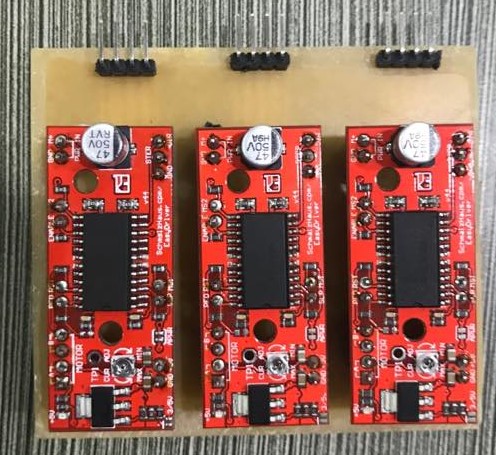
Snapshot after mounting the Easy Stepeer motor Driver.
Software Installation
GRBL FIRMWARE
GRBL FIRMWARE is an open source, embedded, high performance g-code-parser and CNC milling controller written in optimized C that will run on a straight Arduino.
Grbl is a no-compromise, high performance, low cost alternative to parallel-port-based motion control for CNC milling. This version of Grbl runs on an Arduino Mega2560 only.
Download grbl firmware for Arduino Mega form here
The controller is written in highly optimized C utilizing every clever feature of the AVR-chips to achieve precise timing and asynchronous operation. It is able to maintain up to 30kHz of stable, jitter free control pulses. It accepts standards-compliant g-code and has been tested with the output of several CAM tools with no problems. Arcs, circles and helical motion are fully supported, as well as, all other primary g-code commands. Macro functions, variables, and most canned cycles are not supported, but we think GUIs can do a much better job at translating them into straight g-code anyhow. Grbl includes full acceleration management with look ahead. That means the controller will look up to 24 motions into the future and plan its velocities ahead to deliver smooth acceleration and jerk-free cornering.
To Know about GRBL version 1.1 click here here
Flashing GRBl frimware in Arduino Mega
First I followed the tutorail given below
- GND : There are three GND (Ground) pins on the Easy Driver. They are all connected together inside the board. Connect the negative side of your power supply, as well as from any other boards you are using to drive the Easy Driver to one or more of the GND pins.
- M+ : This is the power input to the Easy Driver. Connect this to the positive power supply lead. This should be a 6V to 30V, 2A (or more) power supply that is clean (low ripple).
- A and B : (four pins) These are the motor connections. See below diagrams for how to hook these up. A and B are the two coils of the motor, and can swap the two wires for a given coil (it will just reverse the direction of the motor). Make CERTAIN that this connection to the motor is solid, and NOT through a connector that has any chance of intermittent contact (which will fry the motor driver chip).
- STEP : This needs to be a 0V to 5V (or 0V to 3.3V if you've set your Easy Driver that way) digital signal. Each rising edge of this signal will cause one step (or microstep) to be taken.
- DIR (Direction) : This needs to be a 0V to 5V (or 0V to 3.3V if you've set your Easy Driver up that way) digital signal. The level if this signal (high/low) is sampled on each rising edge of STEP to determine which direction to take the step (or microstep).
- That's it - those are the only signals that you absolutely need to connect to anything. All the rest below are optional - in other words, the Easy Driver sets them to reasonable default values.
- MS1/MS2 : These digital inputs control the microstepping mode. Possible settings are (MS1/MS2) : full step (0,0), half step (1,0), 1/4 step (0,1), and 1/8 step (1,1 : default).
- RST (reset) : This normally high input signal will reset the internal translator and disable all output drivers when pulled low.
- SLP (sleep) : This normally high input signal will minimize power consumption by disabling internal circuitry and the output drivers when pulled low.
- ENABLE : This normally low input signal will disable all outputs when pulled high.
- A3967 Microstepping Driver
- MS1 and MS2 pins broken out to change microstepping resolution to full, half, quarter and eighth steps (defaults to eighth).
- Compatible with 4, 6, and 8 wire stepper motors of any voltage.
- Adjustable current control from 150mA/phase to 700mA/phase.
- Power supply range from 6V to 30V. The higher the voltage, the higher the torque at high speeds.
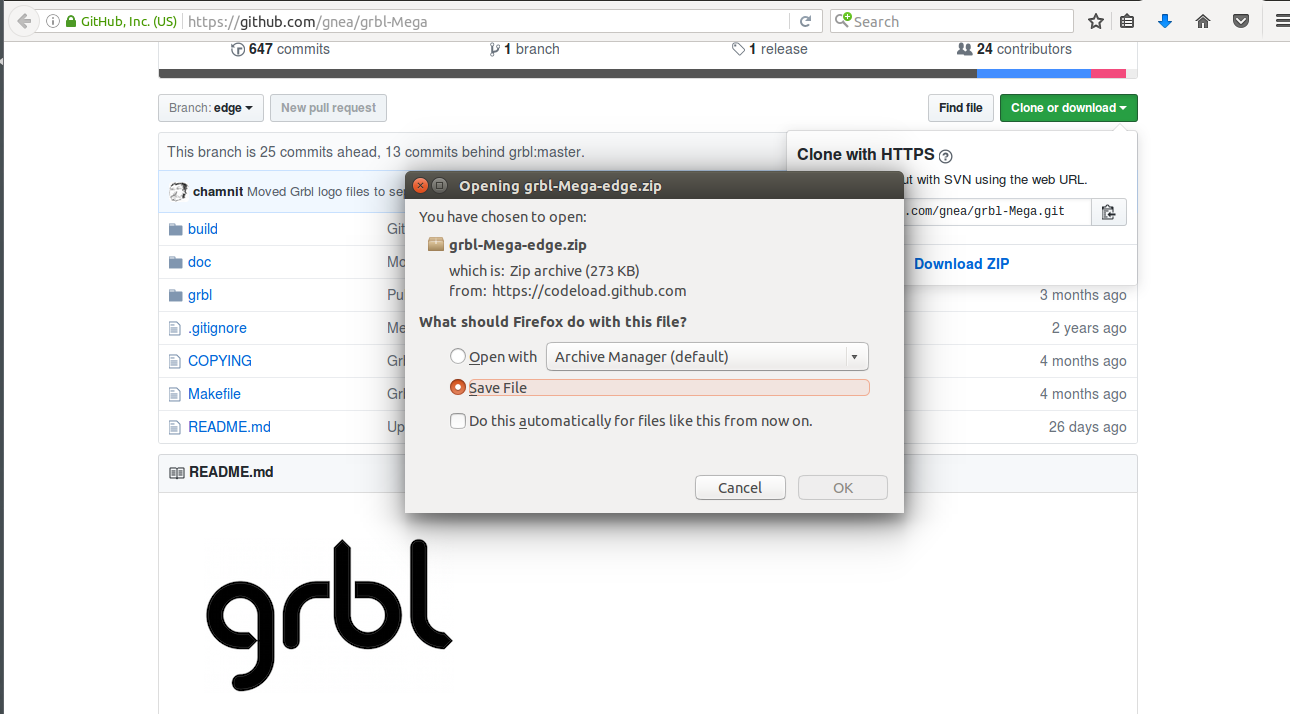
Step 1:
Download the grbl firmware given in the above link and unzip the given folder.
Step 2:
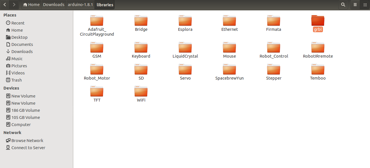
Now open the downloaded folder. Next step is to paste the grbl folder in the library folder of Arduino installed on your sytem.
Step 3:
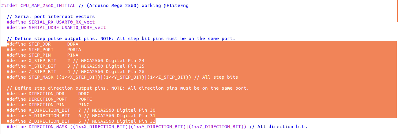
Now open the grbl folder on check the config.h
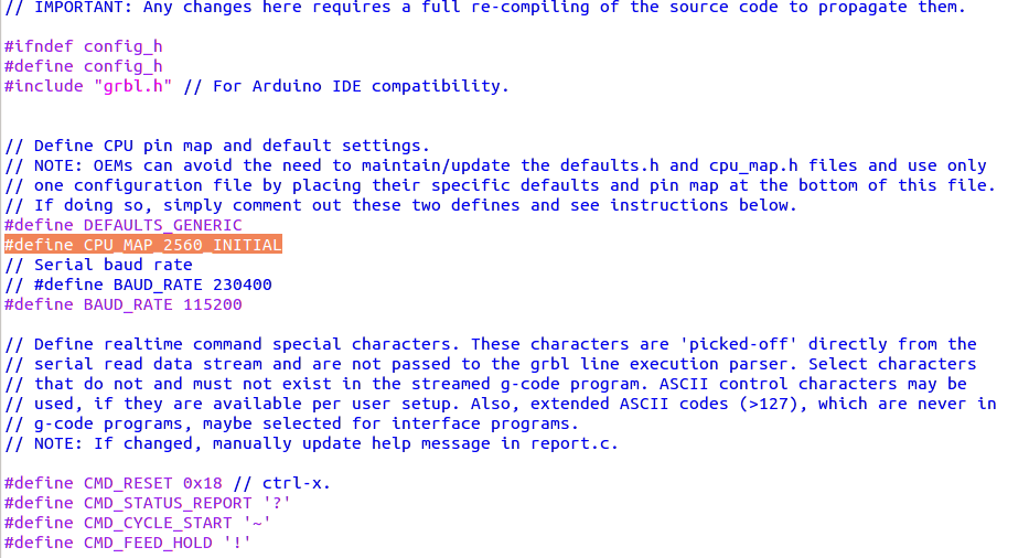 Verify that the firmware is for Arduino Mega 2560
#define CPU_MAP_2560_INITIAL
Verify that the firmware is for Arduino Mega 2560
#define CPU_MAP_2560_INITIAL
Step 4:
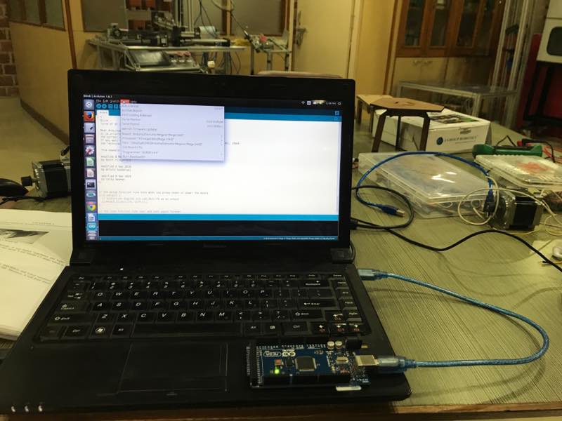
Open ArduinoIDE and connect Arduino Mega to the laptop using USB
Step 5:
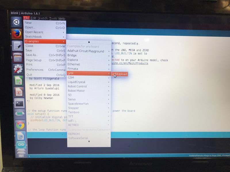
Next open the examples in ArduinoIDE then move to grbl and grbl upload
Step 6:
Upload GRBl in the arduino Mega
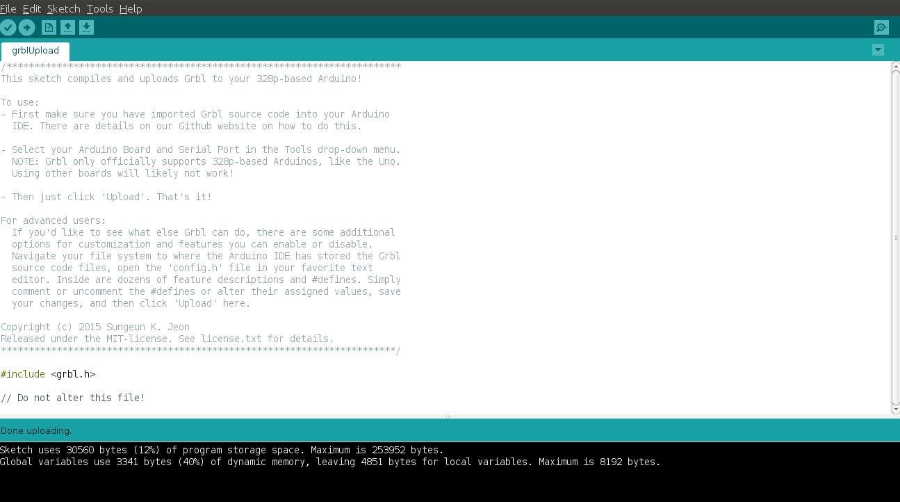
Step 7:
Next Step is to check the grbl firmware through serial communication.
 Now grbl Firmware 1.1e is uploaded in Arduino Mega
To know Grbl's $x=val settings and what they mean click here
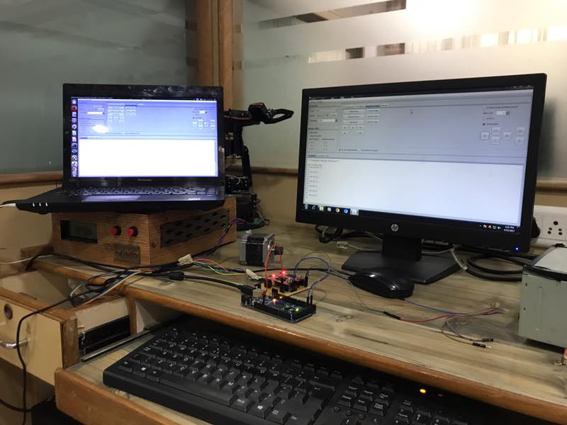
Universal G-code Sender (UGS)
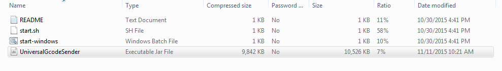
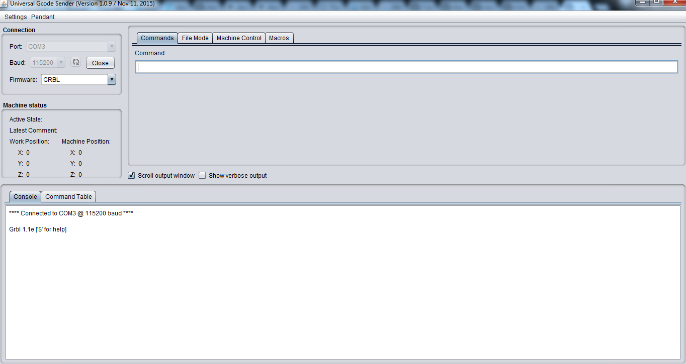
To Download Universal G-code Center click here First i downloaded stable build version 1.0.8. This version was not working with my board. Then to debug the problem i tried with diffrent system, used another Arduino Mega board, changed the cable. But still i was stuck with the problem. Then i switched to the higher version and it started working. In the above downloaded folder open UniversalGcodeSender.jar file
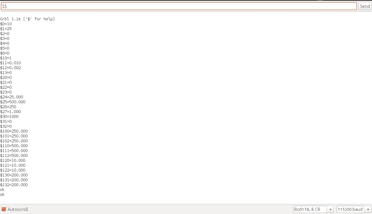
Open the port with baudrate 115200
 Use $$ command to check the firmware

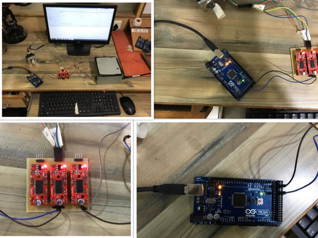
Testing the Board
The default pin configuration for Arduino Mega 2560 is given below. I will recommend others to follow latest pin configuration as there are other configurations available. I suffered with the same problem. When i started working motor was not changing directio. It means my direction pnin was not working. To debug this i applied 5V and GND manually at the direction PIN. Now the motor start changing its direction. Later i got to know the pin configuration for arduino Mega2560 which was used was not latest.
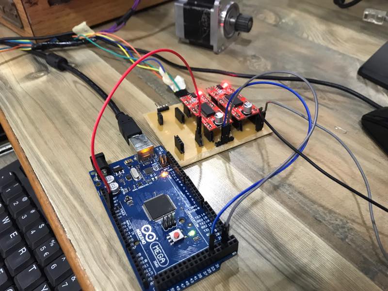
 After making all the connection i tested motors with stepper motor drivers.
Problem Faced
- The mistake which is done by me that i cropped the outer image before making the toolpath. Then it shifted the orgin of external cut and my board got damaged while cutting the outer boundary.
- The default pin configuration available for Arduino Mega 2560 GRBL firmware is not updated. It is highly recommended to use the updated image or check the status in the file cpu_map.h available in grb folder.
- The major problem which i faced is with the diffrent version of Universal G-code Center (UGS). Initailly I was using UGS version 1.0.8 and it was accepting the port but not responding for any input. I thought the problem may be with the board of may be connecting wire.I tried with different possible alternatives and it didn't worked. It took me hours to reach to the version problem. Then I switched to UniveralGcodeSenderv1.0.9 and finally it worked.
- Ground Problem: While working with the board the motor was working correct when command was sent using the dekstop available in the LAB. But using my laptop motor was getting some noise signals. The operation was noisy and not folowing the input. When i discussed the problem with my local instructor he told me the problem may be because of ground port. To resolve the problem i connected the gnd signal of Arduino Mega 2560 and 12V supply. The noise signal was not present after this and motor startd to follow the input.
 |
 |
Machine Design
 |
 |
There was some mistake in the size of machine bed to be fit on the guided path. So we decided to reduce the size using th tools availbale in carpentary shop.
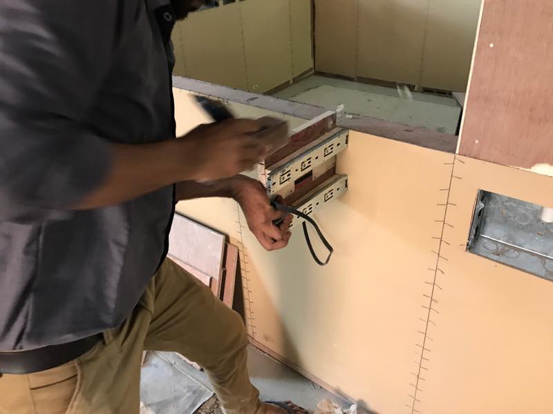
Below is the snapshot of the while assembling the Y axis of the machine.
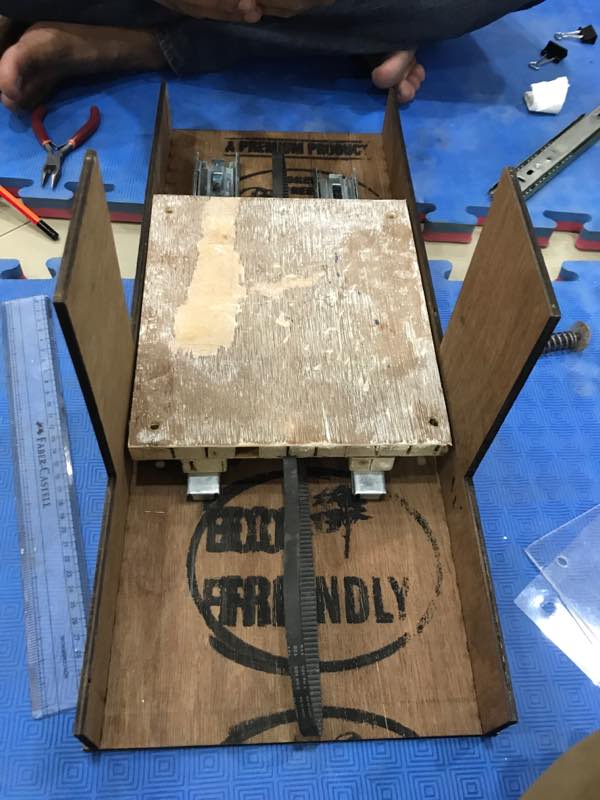
Assembled Machine
 |
 |
 |