Drawing Robot
Make a final project integrating what we have learned and these criterias:
- be your own design
- include an input device and an output device and two other digital fabrication processes
- include 2D and 3D design
- have a mechanical design aspect
- have a license and a plan for distribution
- fabricate, assemble and program a microcontroller board
- all files must be linked and available:
- bill of materials (BOM), preferably with part numbers
- electronics design files (Eagle/Image/.cad/kokopelli - whatever used)
- code
- fabrication files
Files
All file can be downloaded here.
-
Research
I did a few research and made a list of what was made beforehand here.
-
Parts, tools and material test
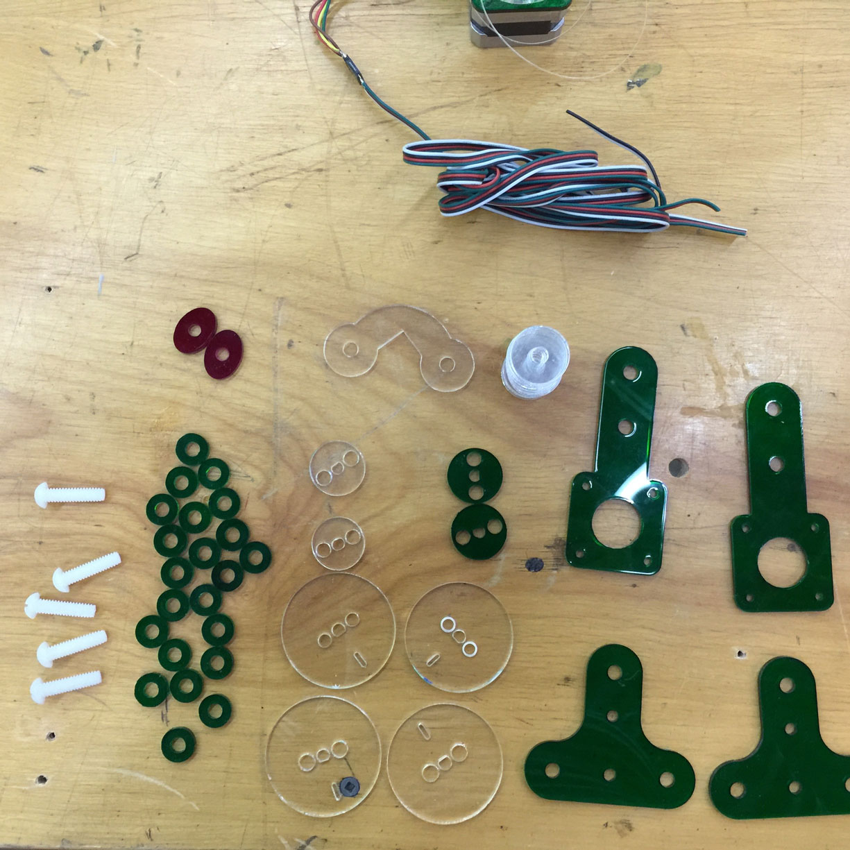
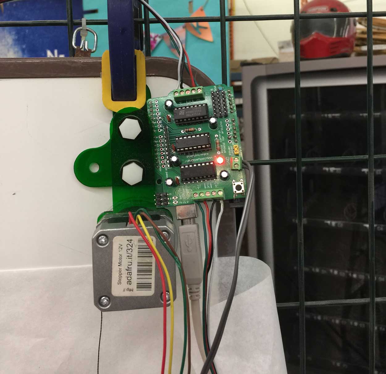
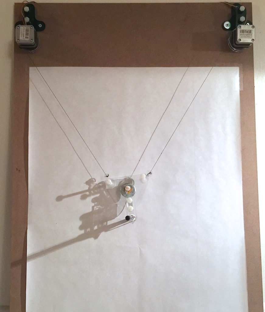
I started making the drawing robot with a model Darcy White did, which I will redesign to work with human interactions. He gave me 2 Nema 17 stepper motors and pieces he had previously cut on CNC and I just start assembling it and connecting wires. He showed me how to hang it. See pictures here.
Drawing file Sketchup Format, DXF Format
1. Getting to know Drawbots
Arduino code to test the motor shield connection to the stepper motor
Programming an Arduino with an Adafruit Shield
I have not yet made my fabduino board compatible with Adafruit motorshield, so I am using an aruino board to design and test my code to control the nema17 motors with Adafruit Motorshield.
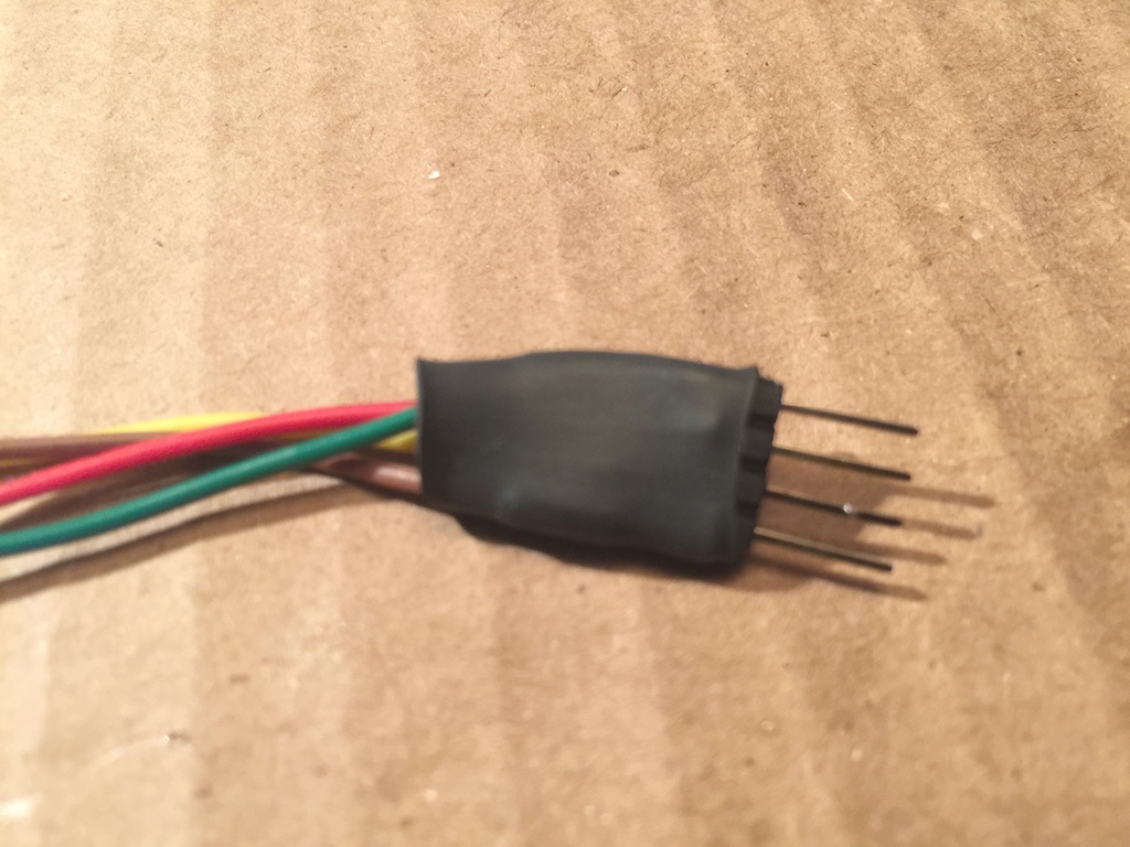
I installed the Adafruit library and read about it and with the help of my friend Doug, from Makerspace North, I wrote a basic code to test if the shield and motor works and if the connexions work. There are 4 wires coming out of the Stepper motors. Red and blue are together on my shield and black and green together. I wire them in the M1: RED BLUE; M2 BLACK AND GREEN for Stepper 1 and Stepper 2. M3: RED AND BLUE; M4 BLACK AND GREEN.
Speed Function of Engine:
"setSpeed" Function >> With this function, I can set the engine speed from 0 to 255 values,
motor1.setSpeed(100); >> In this way the "Stepper1" I have set the pace with which I enter values in parentheses to set the RPM.
Motion Function of Engine:
step (step, direction, mode): This identification of steps and directions information to move the stepper motor mode is where you entered.
step >> Here few steps back to the engine information is entered.
direction >>The motor direction of rotation is entered here. Aspect functions "FORWARD" and "BACKWARD" is defined as.
mode >> Here the movement of the stepper motor type is entered. These;
SINGLE : It operates the motor with energizing a coil. Power saving is useful in places that require but is not very common. It gives less torque motor.
DOUBLE: Run the motor with energizing the two coils. Engine gives full torque.
INTERLEAVE : Coil simultaneously to reduce by half the pitch angle, giving energy. This result in increased resolution and doubles the number of steps. For example, step 200 engine with 1.8 degrees, 0.9 degrees 400 steps, this function takes the value.
MICROSTEP: Smooth motor for driving. Commonly used functions. It provides a smooth transition between steps. But decreases torque.
FORWARD - forward
BACKWARD - back
RELEASE - stop
OneStep (direction, mode) >> This function is available for single-step stepper motors.FORWARD or BACKWARD express written direction to the direction indicated in parentheses.
Stepper1.step(FORWARD); >> In this way the "Stepper1" has been set to the forward direction.
Stepper2.step(BACKWARDS); // Go back
Stepper1.release() >> This function stops the motor torque and the amount of energy that does not interrupt and engine keeps the same torquerelease() >> This function stops the motor torque and the amount of energy that does not interruptand engine keeps the same torque
For more information note: Adafruit Library test
Code Test 1 Adafruit library
//Adafruit Stepper Motor Test #include// Declaration of Adafruit library AF_Stepper Stepper1(200, 1); // Declaration for motor no 1 (NEMA 17 Stepper Motor AF_Stepper Stepper2(200, 2); void setup() { Stepper1.setSpeed(100); Stepper2.setSpeed(100); } void loop() { Stepper1.step(200,FORWARD, DOUBLE); Stepper2.step(200,BACKWARD, DOUBLE); //while(1){}; }
Material Used Version 1
- Arduino Uno
- Adafruit Shiel V 1.0
- Nema 17, stepper motor
- Wires
- Acrylic sheets 3mm
- fishing lines
- Plastic Screws
- Power supply adaptor 12V
- USB A-to-B cable
- Srews (3mm), washers, nuts, bolts
- More basic material listed here
Software
- Sketchup
- Arduino Ide
- Adafruit motor shield library
Mechanics
After May 2nd 2016: Note that at this point, I have left echoFab, my fab lab in Montreal, Canada and have joined Woma team in Paris, France.
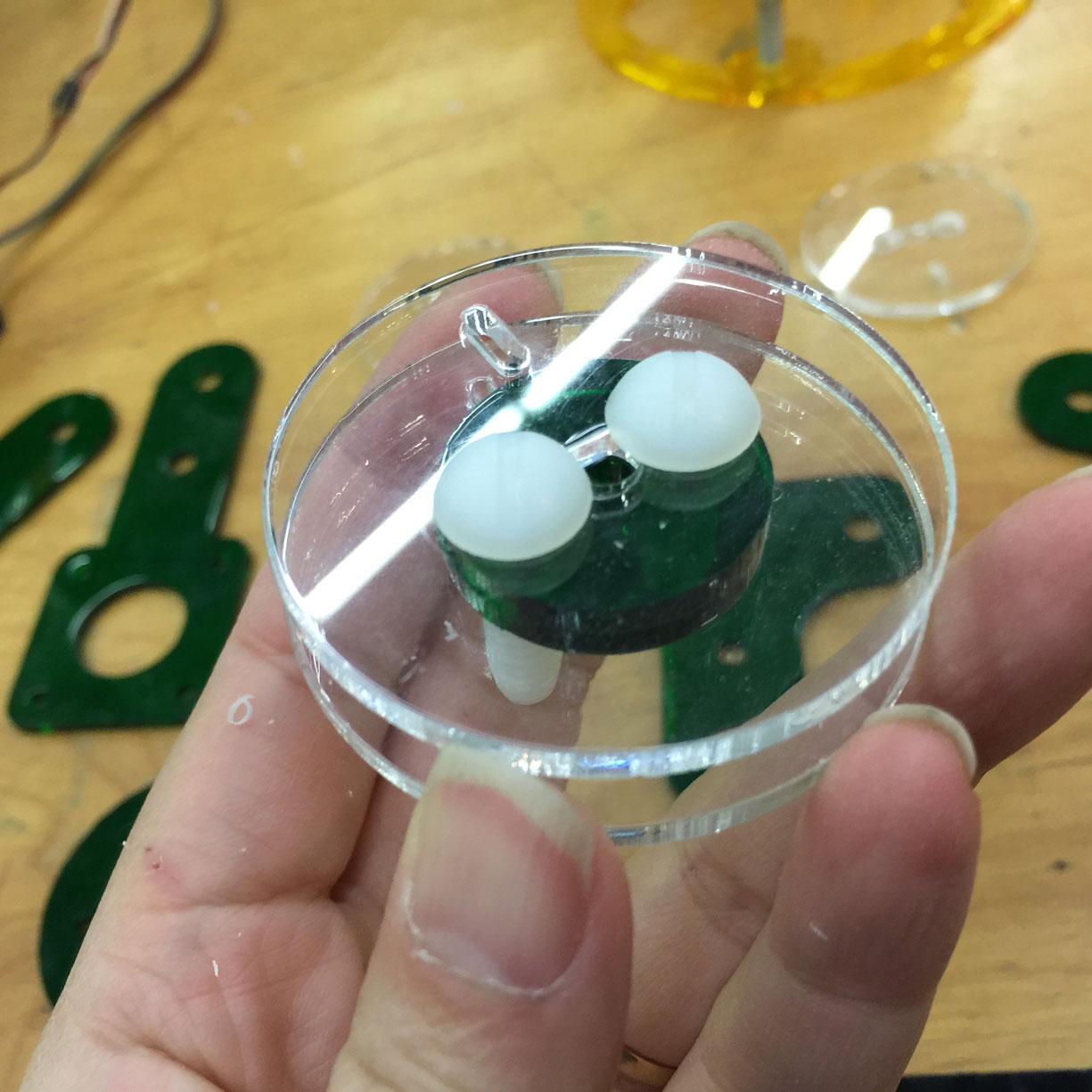
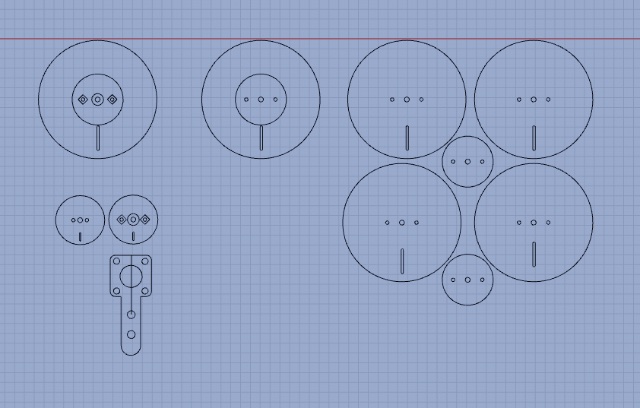
My nema motors, spools attached to it was stolen so I ordered new ones from LetMeKnow Web site here in France. I met the founder, who also is one of our instructor here, Fabien Bogni. This incident was an opportunity for me to make my own spooler in the 3D software that I have learned, Rhino.
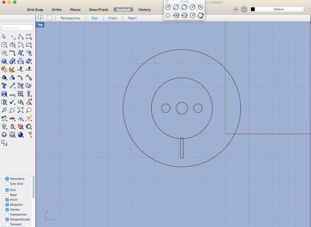
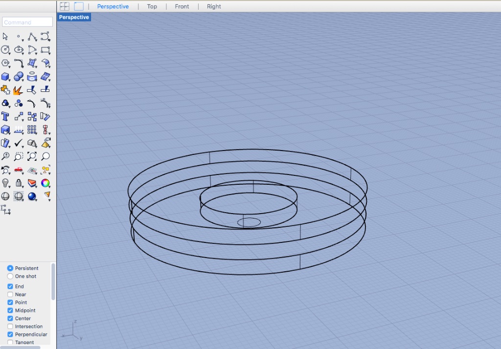
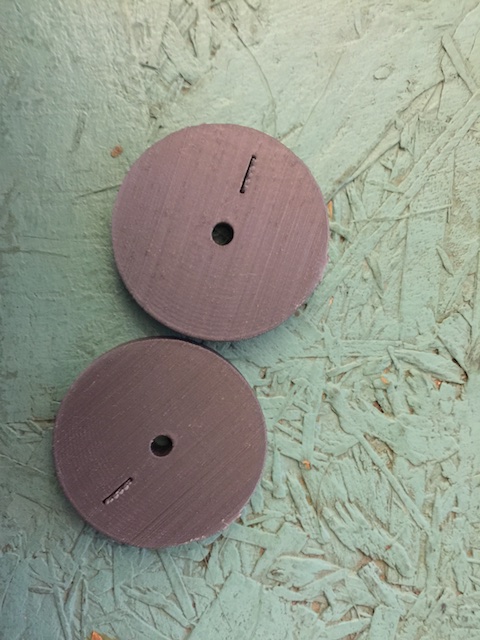
3D printed and laser cut wheels
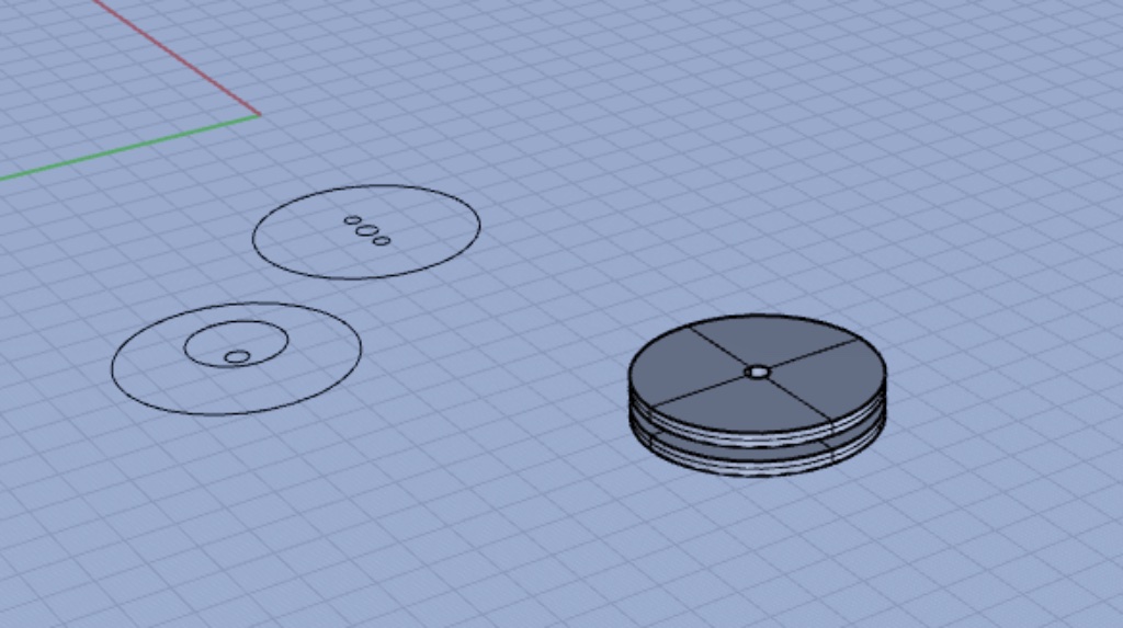
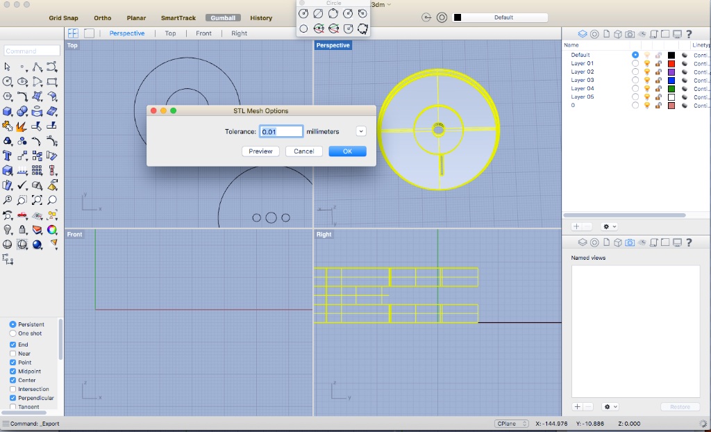
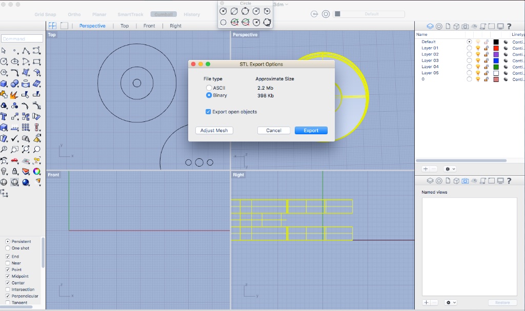
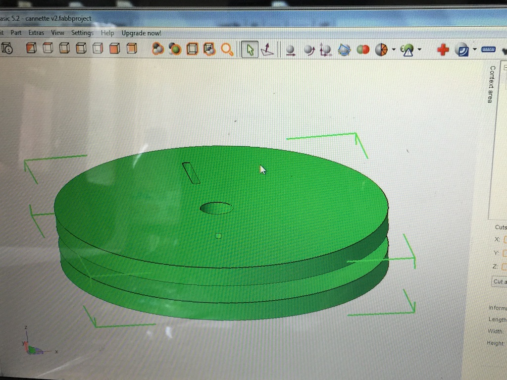
I made two versions for testing, one 3D printed (see file cannette v2_3D.stl and cannette v2.3dm) and one on the laser cutter. See the details of 3D printing pieces here.
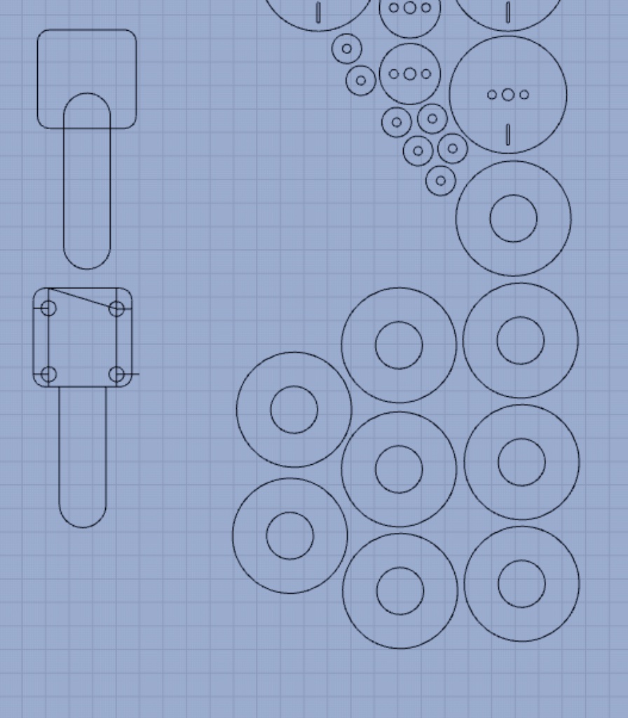
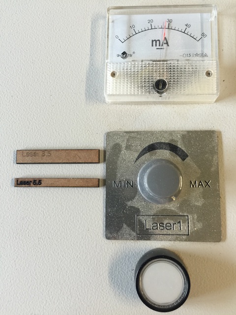
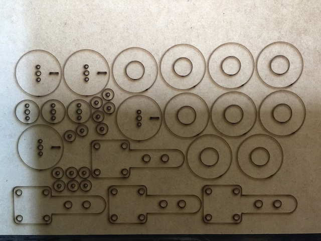 The other wheels were cut with a laser cutter on a 3mm MDF. First run on the laser cutter, the Z axe was set at 5.5mm but they changed the laser head and it is now 8.5mm. I made the modification.
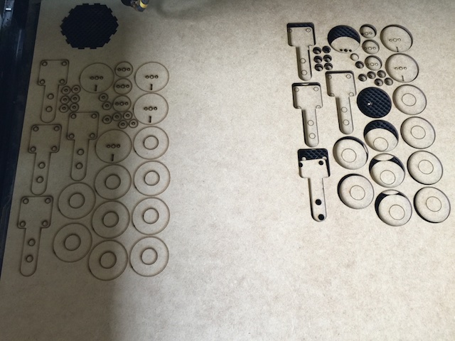
I made two mistakes, I forgot the whole in one of the piece that goes on top of the stepper motor and since I am not using plastic screw that can be cut, I had to make another design.
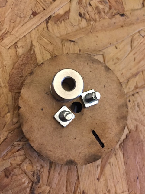
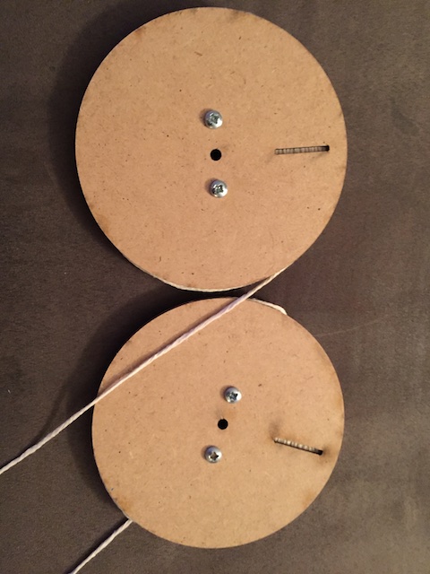
Result of Spool design
Drawbot Version 2 - Integrating piezos
Material used
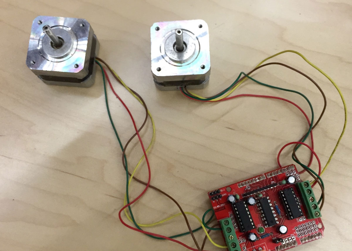
- 2 generic stepper motors, ordered on Addafruit web site
- Arduino uno (for prototyping)
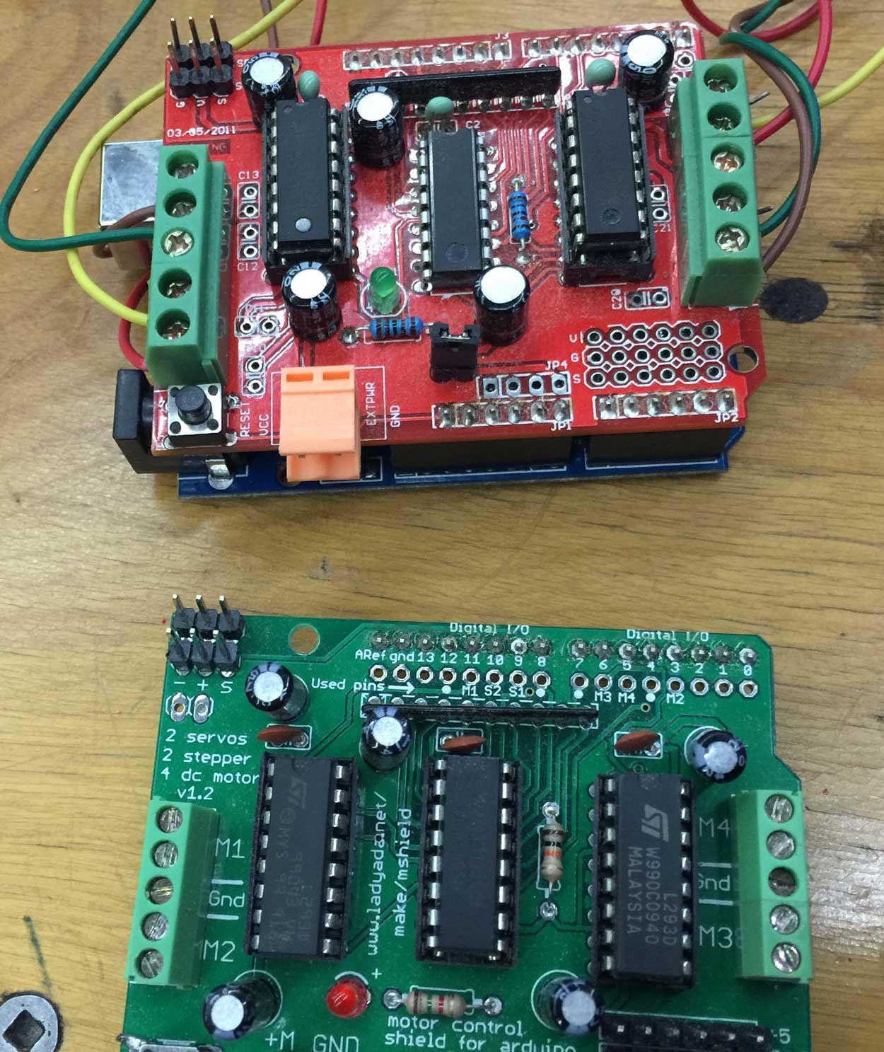
- Motor control shield for arduino (for prototyping) ordered on Addafruit web site
- Acrylic sheets, 3mm
- Screws, wires, fishing lines (spider thread)
- Electric componants (to be listed after making the fab duino and motor shield)
- Sensors : microphone, mouvement detector, distance
Tools
- Soldering Iron
- Heater
- Screw driver
- CNC
Software
- Sketchup
- Rhino
- Arduino IDE
Code
Code version 2 Including Sensor
So the idea is to be able to use
#includeconst int stepsPerRevolution = 200; // change this to fit the number of steps per revolution // for your motor // these constants won't change: const int knockSensor1 = A0; // the piezo is connected to analog pin 0 const int knockSensor2 = A1; // the piezo is connected to analog pin 0 const int knockSensor2 = A2; // the piezo is connected to analog pin 0 const int knockSensor3 = A3; // the piezo is connected to analog pin 0 const int threshold = 100; // threshold value to decide when the detected sound is a knock or not // initialize the stepper library on pins 8 through 11: //Stepper myStepper1(stepsPerRevolution, 8, 9, 10, 11); //Stepper myStepper2(stepsPerRevolution, 8, 9, 10, 11); AF_Stepper myStepper1(stepsPerRevolution, 1); // Declaration for motor no 1 (NEMA 17 Stepper Motor AF_Stepper myStepper2(stepsPerRevolution, 2); void setup() { myStepper1.setSpeed(100); // à Modifier selon les besoins myStepper2.setSpeed(100); } void loop() { // read the sensor and store it in the variable sensorReading: sensorReading = analogRead(knockSensor1); //ON LIT LE CAPTEUR 1 // if the sensor reading is greater than the threshold: if (sensorReading >= threshold) { // step one step: myStepper1.step(100,FORWARD, DOUBLE); // valeur 100 à modifier au besoin } // read the sensor and store it in the variable sensorReading: sensorReading = analogRead(knockSensor2); //ON LIT LE CAPTEUR 1 // if the sensor reading is greater than the threshold: if (sensorReading >= threshold) { // step one step: myStepper1.step(100,BACKWARD, DOUBLE); // valeur 100 à modifier au besoin } // read the sensor and store it in the variable sensorReading: sensorReading = analogRead(knockSensor3); //ON LIT LE CAPTEUR 1 // if the sensor reading is greater than the threshold: if (sensorReading >= threshold) { // step one step: myStepper2.step(100,FORWARD, DOUBLE); // valeur 100 à modifier au besoin } // read the sensor and store it in the variable sensorReading: sensorReading = analogRead(knockSensor4); //ON LIT LE CAPTEUR 1 // if the sensor reading is greater than the threshold: if (sensorReading >= threshold) { // step one step: myStepper2.step(100,BACKWARD, DOUBLE); // valeur 100 à modifier au besoin } delay(100); // delay to avoid overloading the serial port buffer }
Error code
I am having this error with code above and I am scratching my head right now...
/Users/phonesavanh/Documents/Arduino/FabAcademy_final_project_v2/FabAcademy_final_project_v2.ino: In function 'void loop()':
FabAcademy_final_project_v2:25: error: 'sensorReading' was not declared in this scope
   sensorReading = analogRead(knockSensor1);
   ^
Using library Adafruit_Motor_Shield_library at version 1.0.0 in folder: /Users/phonesavanh/Documents/Arduino/libraries/Adafruit_Motor_Shield_library
exit status 1
'sensorReading' was not declared in this scope
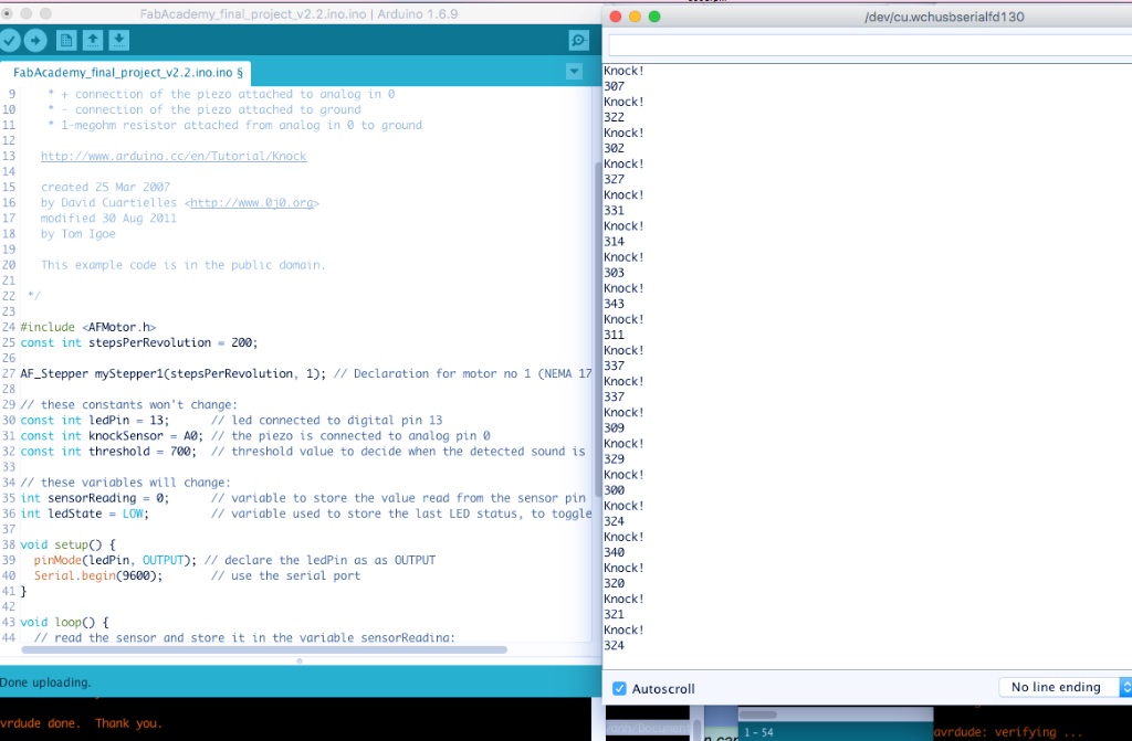
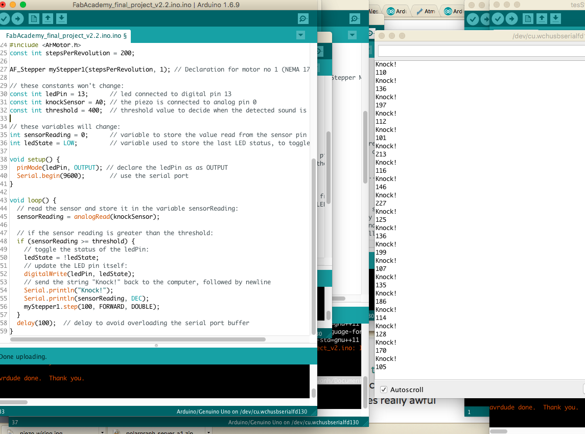
Code v.2.2
Sensor seems to be too sensible see picture below
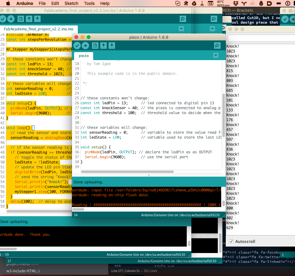
/* Knock Sensor

   This sketch reads a piezo element to detect a knocking sound.
   It reads an analog pin and compares the result to a set threshold.
   If the result is greater than the threshold, it writes
   "knock" to the serial port, and toggles the LED on pin 13.

   The circuit:
    * + connection of the piezo attached to analog in 0
    * - connection of the piezo attached to ground
    * 1-megohm resistor attached from analog in 0 to ground

   http://www.arduino.cc/en/Tutorial/Knock

   created 25 Mar 2007
   by David Cuartielles
   modified 30 Aug 2011
   by Tom Igoe

   This example code is in the public domain.

 */

#include
const int stepsPerRevolution = 200;

AF_Stepper myStepper1(stepsPerRevolution, 1); // Declaration for motor no 1 (NEMA 17 Stepper Motor

// these constants won't change:
const int ledPin = 13;      // led connected to digital pin 13
const int knockSensor = A0; // the piezo is connected to analog pin 0
const int threshold = 400;  // threshold value to decide when the detected sound is a knock or not

// these variables will change:
int sensorReading = 0;      // variable to store the value read from the sensor pin
int ledState = LOW;         // variable used to store the last LED status, to toggle the light

void setup() {
  pinMode(ledPin, OUTPUT); // declare the ledPin as as OUTPUT
  Serial.begin(9600);       // use the serial port
}

void loop() {
  // read the sensor and store it in the variable sensorReading:
  sensorReading = analogRead(knockSensor);

  // if the sensor reading is greater than the threshold:
  if (sensorReading >= threshold) {
    // toggle the status of the ledPin:
    ledState = !ledState;
    // update the LED pin itself:
    digitalWrite(ledPin, ledState);
    // send the string "Knock!" back to the computer, followed by newline
    Serial.println("Knock!");
    Serial.println(sensorReading, DEC);
    myStepper1.step(100, FORWARD, DOUBLE);
  }
  delay(100);  // delay to avoid overloading the serial port buffer
}
I tried adding more resistor for having less sensitivity. 1M Ohms for each piezo. But it ended not to be the problem. I later learn that I had to separeate the threshold of each sensor. This way I can read on the serial monitor which one is making really abnormal hights and low and better troubleshoot.
Making Piezo Boxes
I made this box today to put the piezo in a box. 3D file can be found here like all the rest of the files
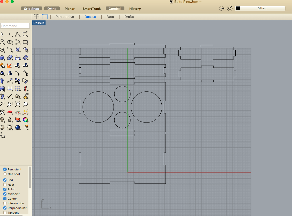
Made little square cuts for the wires.
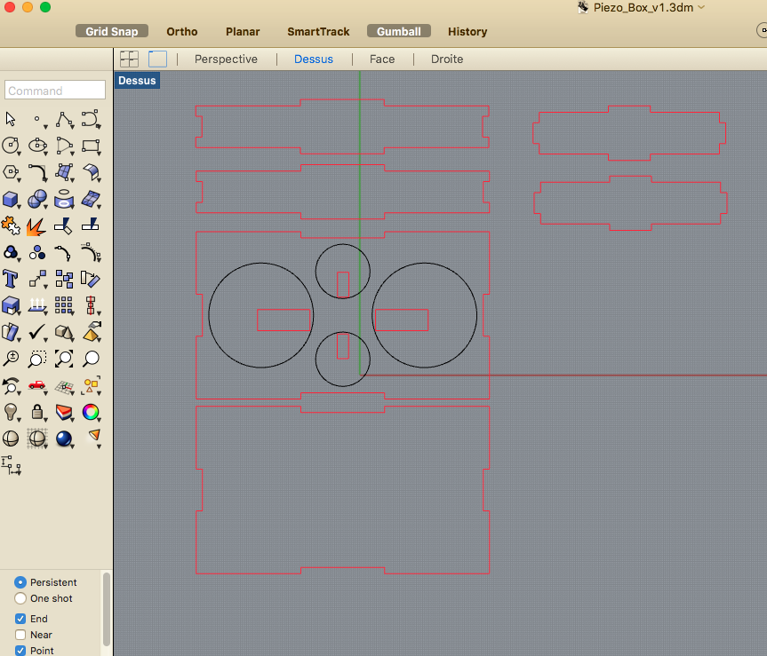
Laser cutting the box and assymbling it
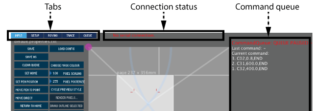
Exploring Polargraph software
I hve been coding for the pass fiew hours without success and decided to explore Polargraph software, a software very popular among drawbot designer, following Euphy's page on Instructable just to see if this machine can draw. I learned that the software can run from the Terminal or Processing, either way, it opens a java Gui so we can set the Machine area, paper area, XY ZERO, the Steps per Revolution of the Nema. The software is using an interleaved step style - it creates kind of intermediate steps. My stepper motors have 200 steps per rev, so I enter 400. The width of my machine is set to 660mm x420mm and my paper size is 420mmx297mm. Odd thing about the software, maybe it is a bug but when clicking on the button there is no arrow to set the number, perhaps we have to writte in Processing or in the Terminal, but I had to click and drag my mouse to move the numbers. Click drag up will decrease the size od my machine width for example. I later found out that it can be specified in the PolargraphController folder in Polargraphsd spec.properties.txt file!
So in details, I first installed the necessary libraries in Processing folder, that would be user/Document/Precession/library/ and copy the Processing sketch in the Processing folder User/Documents/Processing (I am using a Mac). Close the application and open it again, open the sketchbook named: pollargraphcontroler. All details of what I am doing is the Instructable site named above. I choose the serial port, on the control screen text in red.
- Requires the excellent ControlP5 GUI library available from https://github.com/sojamo/controlp5
- Requires the excellent Geomerative library available from http://www.ricardmarxer.com/geomerative/.
- Runnin latest version of porcessing (in my case is 3.1.1). I used 2.1.1 before and it did not work.
- Installed Arduino Sketch inclueded in here. For more informations read this.
Back to coding with arduino
CODE VERSION2.4, I have added 2 piezo and instead of a wind sensor I had a microphone where we can blow in it.
THIS IS THE LATEST CODE THAT WORKED !!! YEAH!! yo can see as stated ealier, I have separated the THREShold so that they can be individually modified to adapt or see which one is causing problems. As it was, if one sensor is not properly solder, like a piezo, the rest of the code dows not work and the motor will just keep on turning forward in a clunky way.
#include// for your motor // these constants won't change: #define KNOCKSENSOR1 A0 // the piezo is connected to analog pin 0 #define KNOCKSENSOR2 A1 // the piezo is connected to analog pin 0 #define KNOCKSENSOR3 A2 // the piezo is connected to analog pin 0 #define KNOCKSENSOR4 A3 // the piezo is connected to analog pin 3 #define SOUNDSENSOR5 A4 // the piezo is connected to analog pin 4 #define THRESHOLD1 50 // threshold value to decide when the detected sound is a knock or not #define THRESHOLD2 50 // threshold value to decide when the detected sound is a knock or not #define THRESHOLD3 50 // threshold value to decide when the detected sound is a knock or not #define THRESHOLD4 50 // threshold value to decide when the detected sound is a knock or not #define THRESHOLD5 50 // threshold value to decide when the detected sound is a knock or not #define STEPSPERREVOLUTION 200 // change this to fit the number of steps per revolution #define SPEED 200 // change speed of the motor // initialize the stepper library on pins 8 through 11: AF_Stepper myStepper1(STEPSPERREVOLUTION, 1); // Declaration for motor no 1 (NEMA 17 Stepper Motor AF_Stepper myStepper2(STEPSPERREVOLUTION, 2); int sensorReading = 0; // variable to store the value read from the sensor pin void setup() { Serial.begin(9600); myStepper1.setSpeed(SPEED); // à Modifier selon les besoins myStepper2.setSpeed(SPEED); } // for your motor // these constants won't change: void loop() { // read the sensor and store it in the variable sensorReading: sensorReading = analogRead(KNOCKSENSOR1); // ON LIT LE CAPTEUR 1 Serial.print("CAPTEUR1 - "); Serial.print(sensorReading); // if the sensor reading is greater than the threshold: if (sensorReading >= THRESHOLD1) { // step one step: myStepper1.step(100,FORWARD, DOUBLE); // valeur 100 à modifier au besoin } // read the sensor and store it in the variable sensorReading: sensorReading = analogRead(KNOCKSENSOR2); // ON LIT LE CAPTEUR 2 Serial.print(" - CAPTEUR2 - "); Serial.print(sensorReading); // if the sensor reading is greater than the threshold: if (sensorReading >= THRESHOLD2) { // step one step: myStepper1.step(100,BACKWARD, DOUBLE); // valeur 100 à modifier au besoin } sensorReading = analogRead(KNOCKSENSOR3); // ON LIT LE CAPTEUR 3 Serial.print(" - CAPTEUR3 - "); Serial.print(sensorReading); // if the sensor reading is greater than the threshold: if (sensorReading >= THRESHOLD3) { // step one step: myStepper2.step(100,FORWARD, DOUBLE); // valeur 100 à modifier au besoin } sensorReading = analogRead(KNOCKSENSOR4); // ON LIT LE CAPTEUR 4 Serial.print(" - CAPTEUR4 - "); Serial.print(sensorReading); // if the sensor reading is greater than the threshold: if (sensorReading >= THRESHOLD4) { // step one step: myStepper2.step(100,BACKWARD, DOUBLE); // valeur 100 à modifier au besoin } sensorReading = analogRead(SOUNDSENSOR5); // ON LIT LE CAPTEUR 5 Serial.print(" - CAPTEUR5 - "); Serial.println(sensorReading); // if the sensor reading is greater than the threshold: if (sensorReading >= THRESHOLD5) { // step one step: myStepper1.step(100,BACKWARD, DOUBLE); myStepper2.step(100,BACKWARD, DOUBLE); // valeur 100 à modifier au besoin } delay(100); // delay to avoid overloading the serial port buffer }
Preparing for presentation
June 22nd - Today I had to prepare for final project presentation. There are so many things that I have learned since the beginning of the week and one thing just still amaze me how all is being done in the Terminal. One of the thing that had to be done fore presentation was a 1min video in MP4 HTML5 Format. I used to work as a web designer and one in a while I have been asked to convert vidéo and that is no big deal. I had 3 hours left before sending all files for presentation this morning and I focussed on making my movie in iMovie, a drag and drop, as easy as can be an app. After all, I just had to chose the file format, Directly on youTube or as a file for example. I choose as a file, and when it came to converting, my video converter app was outdated! I looked at Roman and Thomas's chat on slack and basically I understood MP4 HTML5, 1080 wide, as small and light as possible....... ok. Did the conversion, chose HTML5 output! =====>!!!! VIDEO NOT READABLE ON CHROME ----!!!!! Safari browser only. Went back on Neils instruction page which I have read before and was wondering why there would be so many little code next to the preference. MP4 HTML5, 1080 wide, as small and light as possible....... That's about the only information I picked up. Until I realise reading Roman's comments with Frédéric :
-
rkutin [8:41]
by export from iMovie (share -> file) -
fjaffres [8:43 PM]
doing "brew install libav",
After installation, I can now refer to Neil's Gershenfeld's page and enter this code command:
avconv -i input_video -vcodec libx264 -crf 25 -preset medium -vf scale=-1:1080 -acodec libmp3lame -q:a 4 -ar 48000 -ac 2 output_video.mp4became this one in my case:
avconv -i /Volumes/PSDATA/**Dropbox/Dropbox/04_PHONESAVANH.COM/fabacademy\ 2016/presentation2.mp4 -vcodec libx264 -b:v 1000k -vf scale=-1:1080 -an /Volumes/PSDATA/**Dropbox/Dropbox/04_PHONESAVANH.COM/fabacademy\ 2016/presentation2opt.mp4That meant I have converted my video to an mp4 HTML5 with MP3 sound type file with a sound rate of 48Khz. Nope, I did Machine that Makes and many other programing that involves the terminal and I still dind't have the reflexe to think that our Teacher Neil Gershenfeld is alway in the Terminal, even when he Googles, as my friend Thomas Feminier told me! So his instructions are in command lines...! I wanted to share with other non engineer, or non cracked computer wizz the how to make this HTML5 video, all platforms wide compatible, throught the TERMINAL.
All is ready for presentaion now...! The next few days until July 7th, final date for submission to graduate in Shenzhen, China at FAB12 Conference, will be to complete uncompleted assignments and documentations. I still have
- Molding and Casting
- Output Devices
- Interface and Application Programming
- Applications and Implications
- Finnish my final project
- Flight back home to Canada!!! (June 26 2016)
June 7th - Back to Quebec!
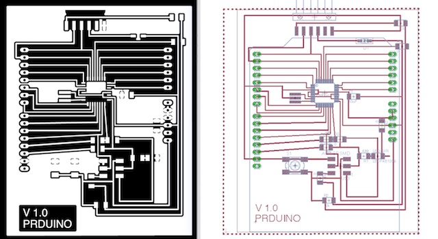
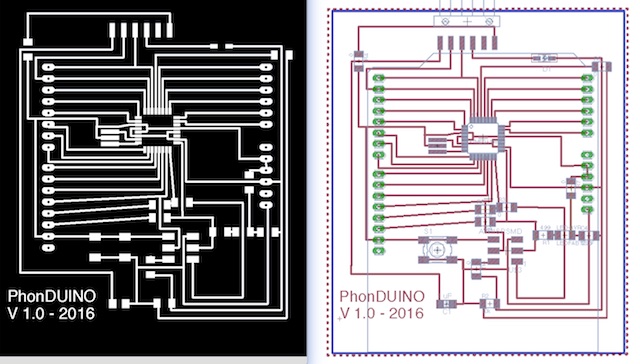
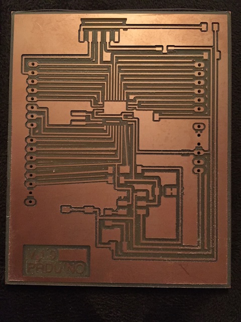
I have been back to Canada since June 26th. I have been working almost non-stop to finish this in due time. I have been able to almost finish all my work assigments and have worked my electronic components of the drawbot which is a circuit board arduino base on < a href="http://fabacademy.org/archives/2015/eu/students/papaleo.alessandro/project/index.html" target="_blank">Alessandro Papaleo Brain Motor called the PhonDuino. This board will later be use with Adafruit Motorshield and later a home made Adafruit Motorshield. I have worked with Roman and an upgrade of this collaborative version is named PRDUINO.
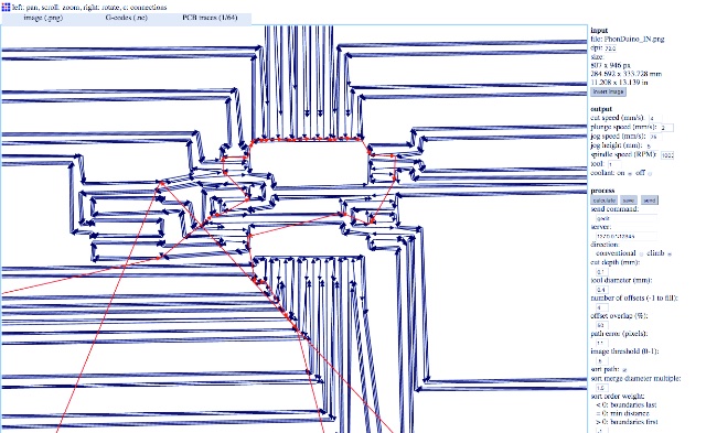
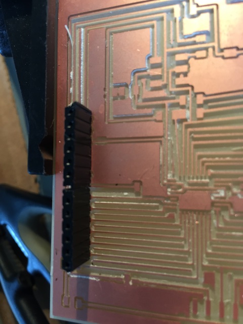
See version v1 of the different board. The first board, even thought I changed the parts for fab library, there was a problem near the microprocessor where the lines were very closed. The result is very surprising because the CNC did not cut that surrounding part at all.
Board design
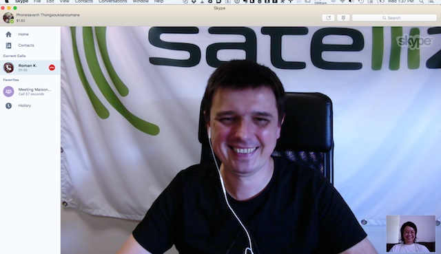
Working with Roman via Skype:
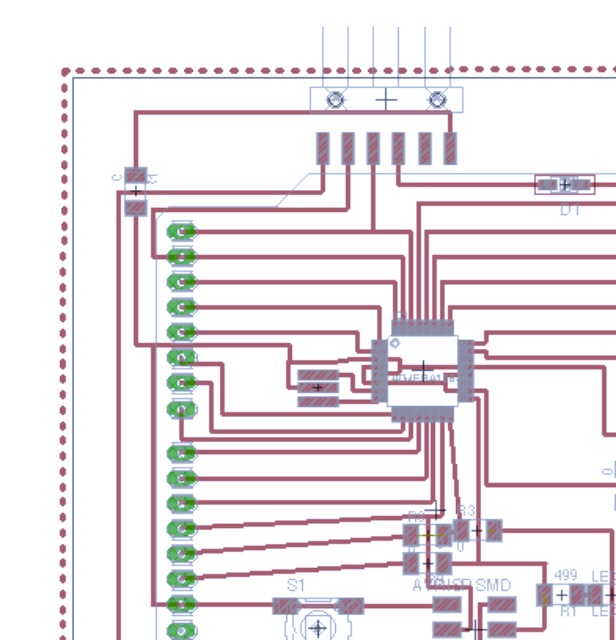
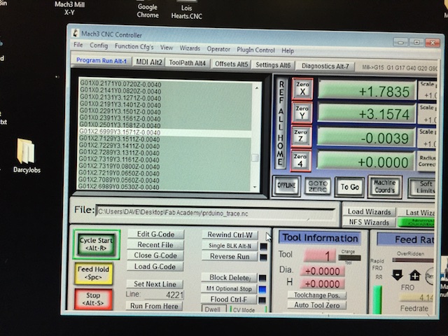
Toolpath PHONEDUINO PROBLEM NEAR THE MICROPRECESSOR
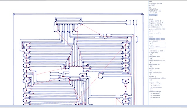
 BETTER TOOLPATH WITH THE HELP OF ROMAN! THANK YOU!
Result
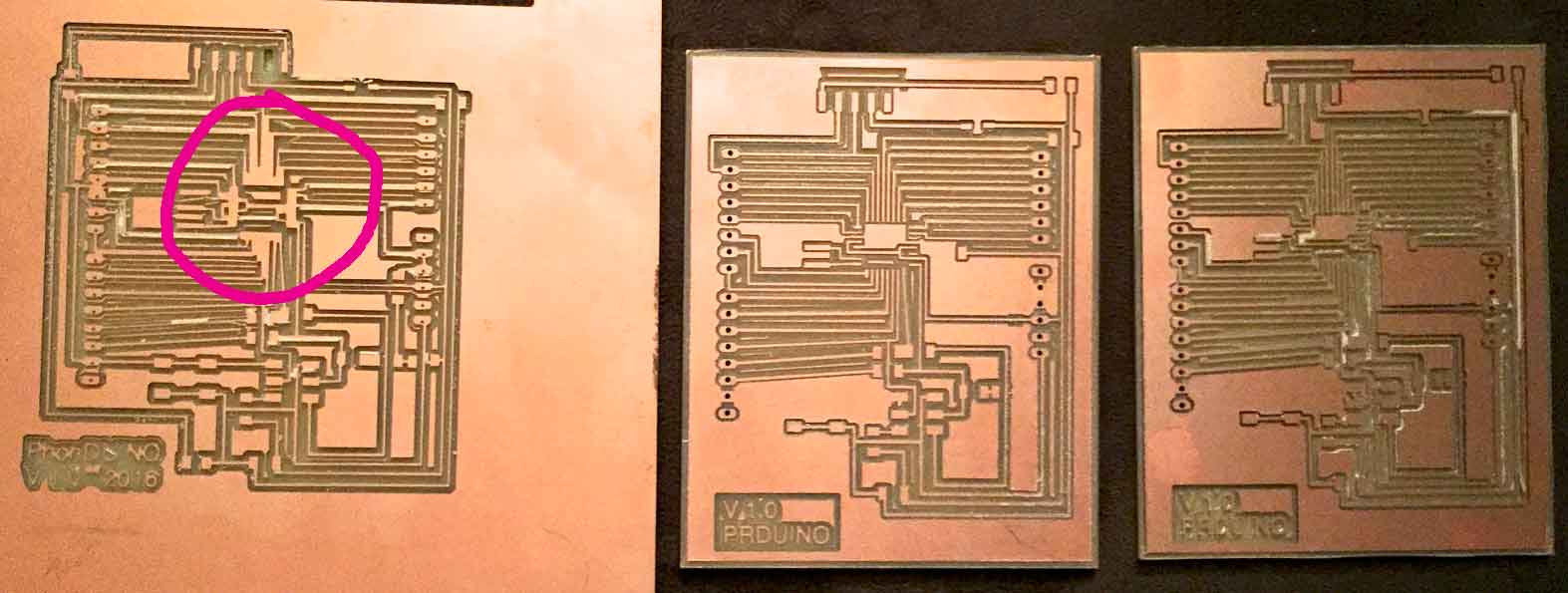
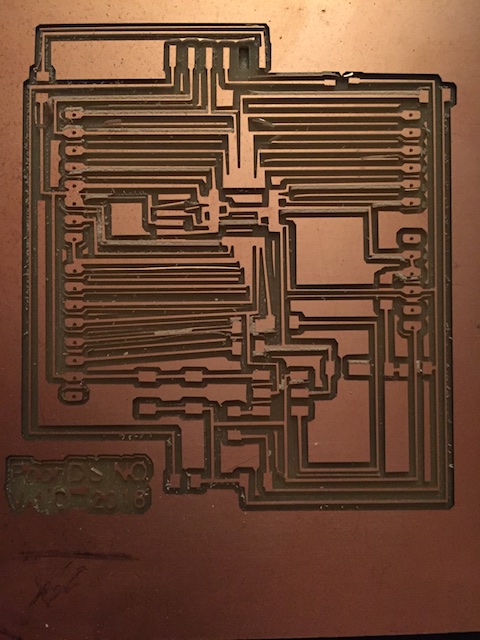
 I learned that on Mach3 I was able to make a return when cutting by selecting the pose button and the start again. I had to went back and forth a couple of time to get the missing parts. Eventually I had to cut another board because all the left side was not at the same level, enought to make this little problem. See on this picture that part of the parth was not cut properly.
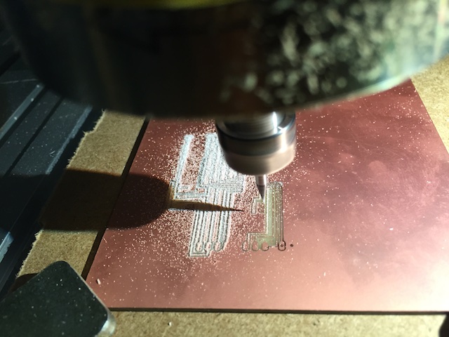
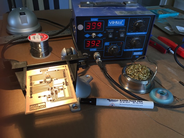
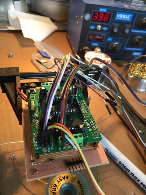
 I use this flux for my final project. I notice that after a few weeks our board would have green stain on it and that the flux was corrosive and needed to be cleaned. This one is a non corrosive" flux:
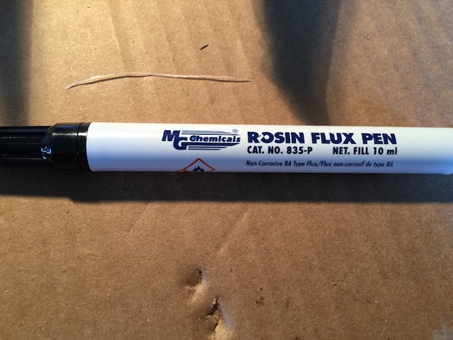 The Pin were very hard to solder with no copper on the other side, so I tried soldering on the other side of the board but oups!! I forgot to verify the geometry with Adafruit Shield, like Roman suggested (I should always carefully listen to Roman!) and desolder with the heating gun.
 AND VOILÀ! TIME TO PROGRAM IT!
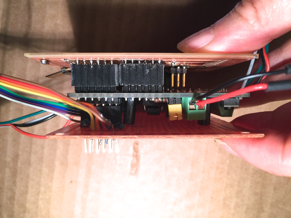
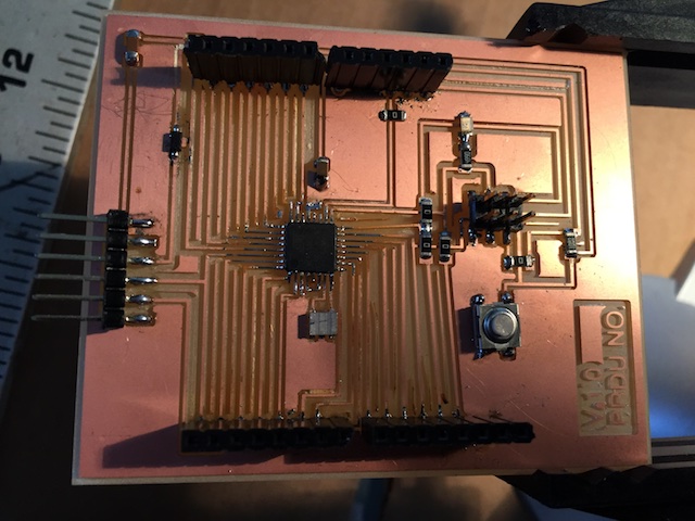 I tested the pin alignment with the Adafruit shield and all look fine:
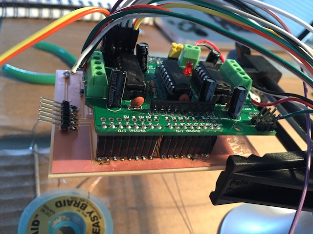
BOM
The buil of material for this version can be find here.
Programing the board
I tried using Satshakit way to program the board, it did not work Bad signature was the verbose error code. I used Alessandro Papaleo and it din't not work at first because I have put a wrong microprocessor.So both resulted in no positive response: I had this error problem shown below. I tried what Alessandro Papaleo did and it did not work either. Guess I will have to search for that!
/Applications/Arduino.app/Contents/Java/hardware/tools/avr/bin/avrdude -C/Applications/Arduino.app/Contents/Java/hardware/tools/avr/etc/avrdude.conf -v -patmega328p -cstk500v1 -P/dev/cu.usbmodemFA141 -b19200 -e -Ulock:w:0x3F:m -Uefuse:w:0x05:m -Uhfuse:w:0xDE:m -Ulfuse:w:0xFF:m

avrdude: Version 6.0.1, compiled on Apr 14 2015 at 16:30:25
         Copyright (c) 2000-2005 Brian Dean, http://www.bdmicro.com/
         Copyright (c) 2007-2009 Joerg Wunsch

         System wide configuration file is "/Applications/Arduino.app/Contents/Java/hardware/tools/avr/etc/avrdude.conf"
         User configuration file is "/Users/phonesavanh/.avrduderc"
         User configuration file does not exist or is not a regular file, skipping

         Using Port                    : /dev/cu.usbmodemFA141
         Using Programmer              : stk500v1
         Overriding Baud Rate          : 19200
         AVR Part                      : ATmega328P
         Chip Erase delay              : 9000 us
         PAGEL                         : PD7
         BS2                           : PC2
         RESET disposition             : dedicated
         RETRY pulse                   : SCK
         serial program mode           : yes
         parallel program mode         : yes
         Timeout                       : 200
         StabDelay                     : 100
         CmdexeDelay                   : 25
         SyncLoops                     : 32
         ByteDelay                     : 0
         PollIndex                     : 3
         PollValue                     : 0x53
         Memory Detail                 :

                                  Block Poll               Page                       Polled
           Memory Type Mode Delay Size  Indx Paged  Size   Size #Pages MinW  MaxW   ReadBack
           ----------- ---- ----- ----- ---- ------ ------ ---- ------ ----- ----- ---------
           eeprom        65    20     4    0 no       1024    4      0  3600  3600 0xff 0xff
           flash         65     6   128    0 yes     32768  128    256  4500  4500 0xff 0xff
           lfuse          0     0     0    0 no          1    0      0  4500  4500 0x00 0x00
           hfuse          0     0     0    0 no          1    0      0  4500  4500 0x00 0x00
           efuse          0     0     0    0 no          1    0      0  4500  4500 0x00 0x00
           lock           0     0     0    0 no          1    0      0  4500  4500 0x00 0x00
           calibration    0     0     0    0 no          1    0      0     0     0 0x00 0x00
           signature      0     0     0    0 no          3    0      0     0     0 0x00 0x00

         Programmer Type : STK500
         Description     : Atmel STK500 Version 1.x firmware
         Hardware Version: 2
         Firmware Version: 1.18
         Topcard         : Unknown
         Vtarget         : 0.0 V
         Varef           : 0.0 V
         Oscillator      : Off
         SCK period      : 0.1 us

avrdude: AVR device initialized and ready to accept instructions

Reading | ################################################## | 100% 0.02s

avrdude: Device signature = 0x000000 (retrying)

Reading | ################################################## | 100% 0.02s

avrdude: Device signature = 0x000000 (retrying)

Error while burning bootloader.
Reading | ################################################## | 100% 0.02s

avrdude: Device signature = 0x000000
avrdude: Yikes!  Invalid device signature.
         Double check connections and try again, or use -F to override
         this check.


avrdude done.  Thank you.
Update!!!I got the correct microprocessor and followed Alessandro's way to programmed and it worked!
Montage
- TODAY JULY 13th
- Assembling board and Nema to the prDuino + Adafruit
Hard wiring resistor to Adafruit Motor Shield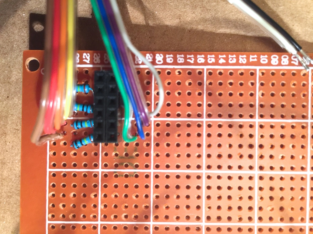
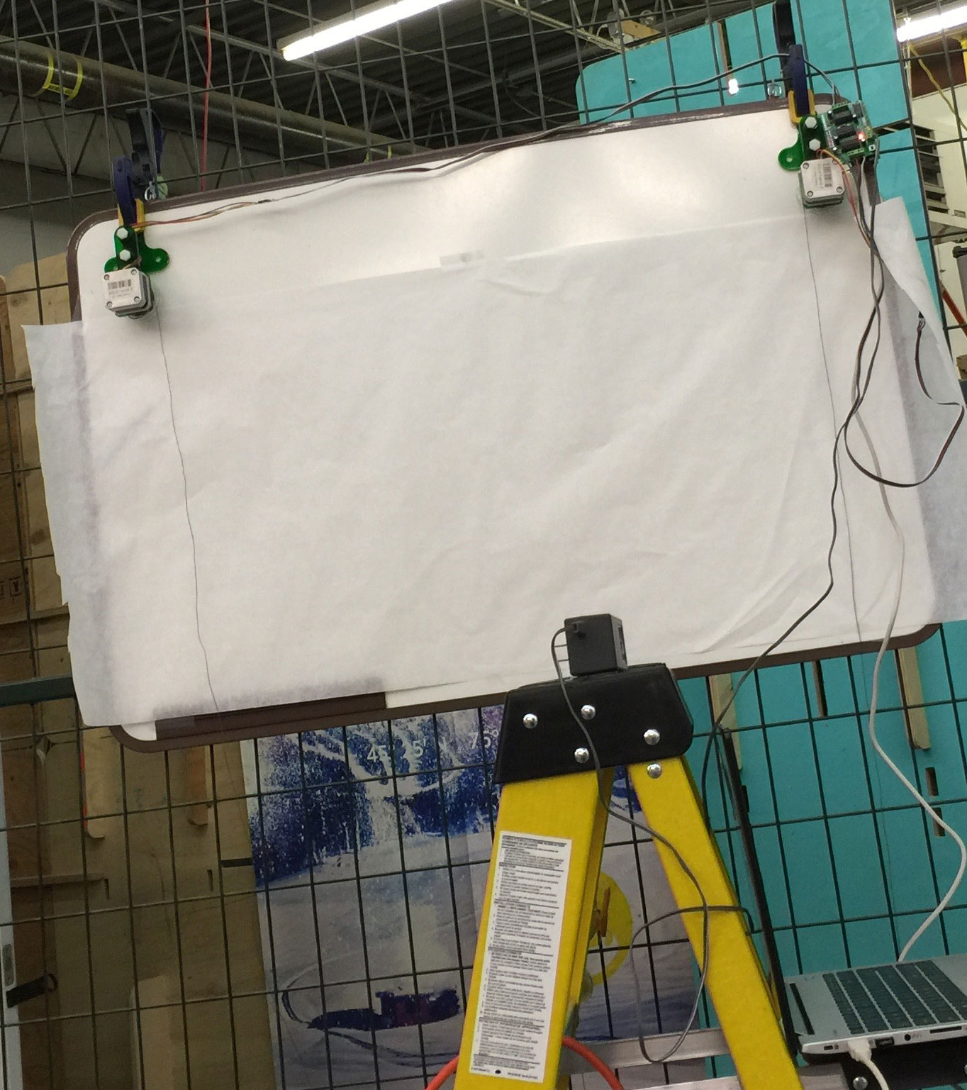
- Assembling Wall draw bot on wood pannel, I will eventually try it on a glass window. This could be very nice!
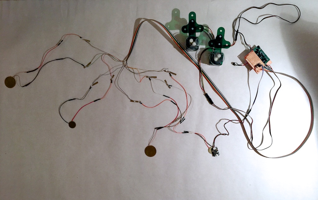
- Made piezo sensor floor, here is what it looks like underneeth. People can jump and walk or the microphone will pick up the wind or the sound.
- TO DO: Draw a piezo and micro sensor wiring on fritzing to better document final project, unfortunatly I am running out of time!!!
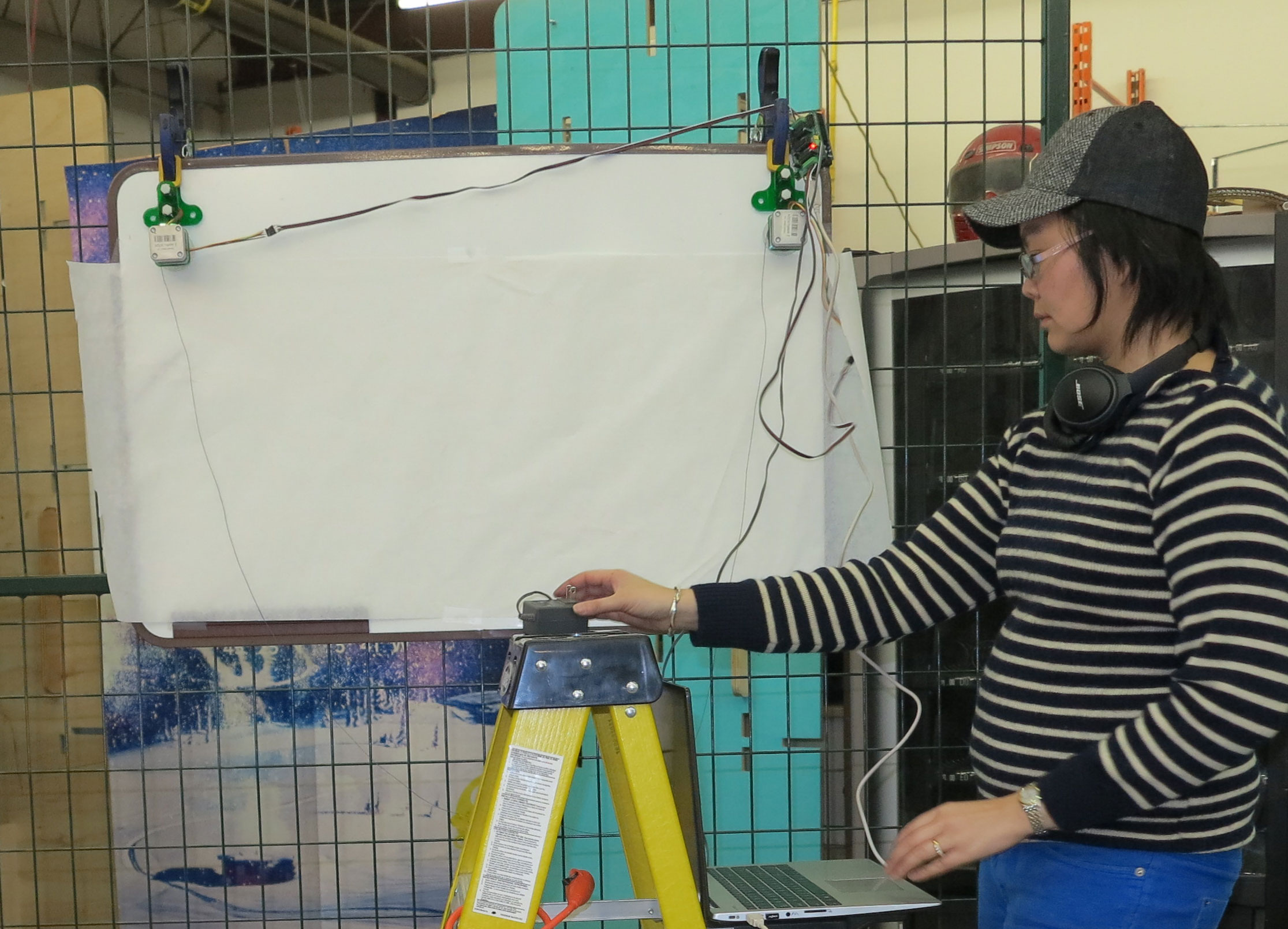
- The Arduino fabMade prDuino did not work porperly so I ended by using an Arduino Uno, I made the test and it gave the same result so it is not the Arduino. I will have to play around with the code setting and Threshold, Speed, and Number of steps to get a better result. One of the Nema Motor overheated and started to studdered. This is quite an ending!!!
Result
Things left to do for my final project
Well this is the last and final update for first round of evaluation, hopefully I will graduate in Shenzhen, China at the FAB12 conference which was my goal when I left for Paris with only two months left of the Fab Academy Program. My first goal was to do the program in two year but I changed my mind and I am very happy because it kept me going and motivated to work almost non-stop! I am very happy of all the work accomplished and are gratefull to all those that help and supported me at Woma/Volumes and Terance in North Carolina. I have learned to make, cut and used machine a lot faster and more efficiently. I learned to code, make a PCB and even make a Machine in less than 3 days!!! Amazing learnings and adventures!!!
Note
Lots of details on the final projects are also on this page.