Project description

"Can I crate an arduino? - Yes, you can! :-)" Something like this I hear during the first day presentation of the processes and explanations for the methods applies in FabAcademy.
So? Can we create an arduino?
Yes we can :-)

Together with Phonesavanh Thongsouksanoumane we decided to create an arduino compatible board (PR Duino), that will be able to accept standard shields (in fact our requiredments is some specific shields that are compatible with classical Arduino UNO nboard).

Problems that we need to resolve are clear:
- Board need to have pins located and ordered in same way as it is on Arduino UNO board
- Board need to use one layer PCB plate (as we have access to machines that permit simple mill the one side boards)
- Board need to be "millable" by using accessible for us 1/64" endmill.
- No need of special features for the moment (no needs of 3.3V and WiFi). Let add FTDI for simle programming and accessing.

Realization

We work as geo-delocalized team splitted on 2 continents... :-) Few hours of TZ difference. So communication by skype / slack.

My role is design / milling test and Phonesavanh, as the main consumer of this board, (she will use this board in prototyping of main project) will do soldering and real application of board in real project.

To make traces we get the pinout of real Arduino, and pinout of Atmega168 - then we placed traces to deliver to good pins (we used the component that have dimentions of a shield, that permit us to align all traces and pins)

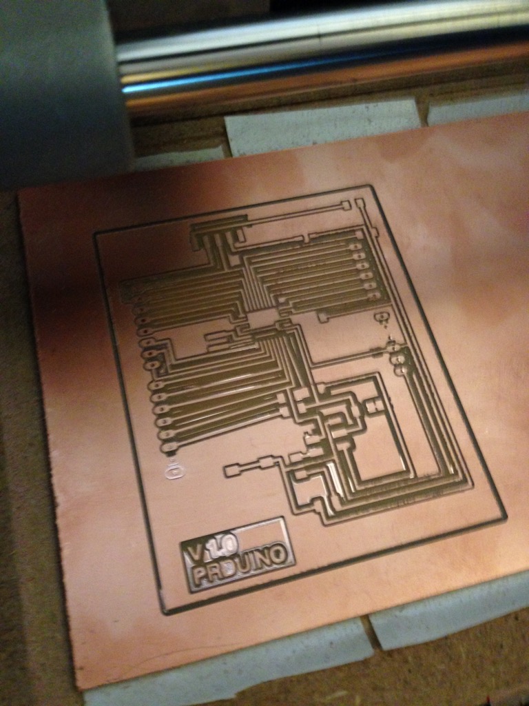
So here we are. Below is the schematic and board


One of the main challange is to avoid the dual side boards. I used 0 Ohm resistance to bypass the traces. We have 6 of them! Probably in next version we can reduce number of leds. As well we can pass to chip with integrated USB communication to simplify connections in the future.

Added maximal GND surface.

Preparation for milling

Let pass to mlling! Standard chip case does not permit to mill it simply by using the 1/64" mill. Traces betwee pins of ATMEGA chip will not be milled. There are 3 different ways to resolve it:
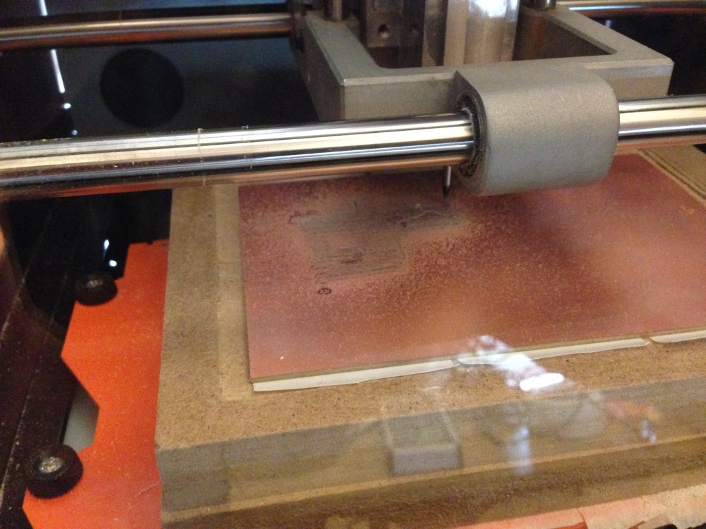
  • Fix case for the contoller. We can do it in library (cf. my tips about components ). This way will take some time, but it will be definitive fix.
  • Fix it on the phase of export to image (using GIMP editor fix inter pins spaces by simple copy / paste black surface). It take short time, but it need to be repeated each time we want to mill new board (after changes). I used this method to produce the traces, but just because of leak of time.
  • Tricking during milling. We can say that our endmill is not 0.39 (0.4) mm diameter, but 0.3mm - that will permit to fabmodules to create path even in places where it was not possible before. But will have risk to cut some traces or to make them thiner than we planified. So this method is faster (for lazy persons) but I don't like it.
  • So as I mentioned above - fixed in GIMP by copy paste. Now we have traces / holes and cut.
    Milling

    Now milling by Rolland SRM-20.

    Visual control

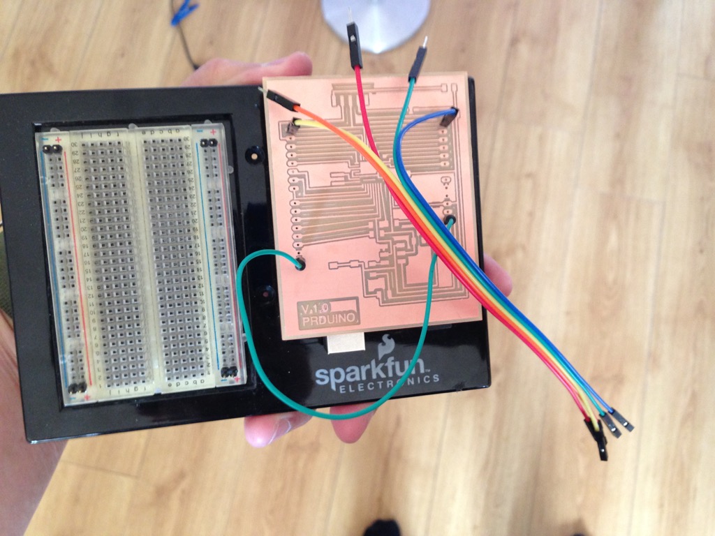
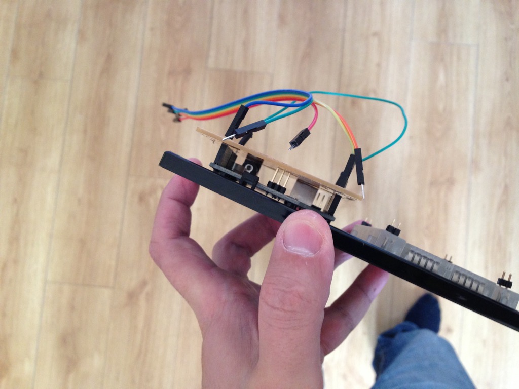
    One of the goal is compatibility with Arduino UNO, so pins need to be on same physical places. Let check this out.
    I used 4 pins that I put to extream holes and put the new board on the Arduino UNO board as a shield. And it match!


    Now we pass to soldreing / programming and applying to real project prototyping!

    Team work is awesome!