Assignments
design, make, and document a parametric press-fit construction kit
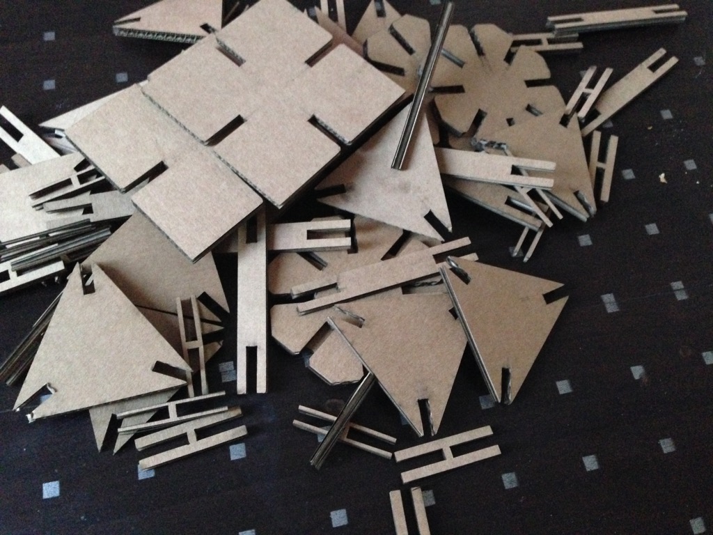
For my press-fit construction kit I decided to use cardboard material as a cheaper and more simple to operate. The choice mostly based on first experience limits. The idea of the kit is the mix of different shapes based on thickness of material that can be produced "on demand" in agile way. There is no fixed form or idea for this kit and it is not done to produce something special. Just an open mind thing.
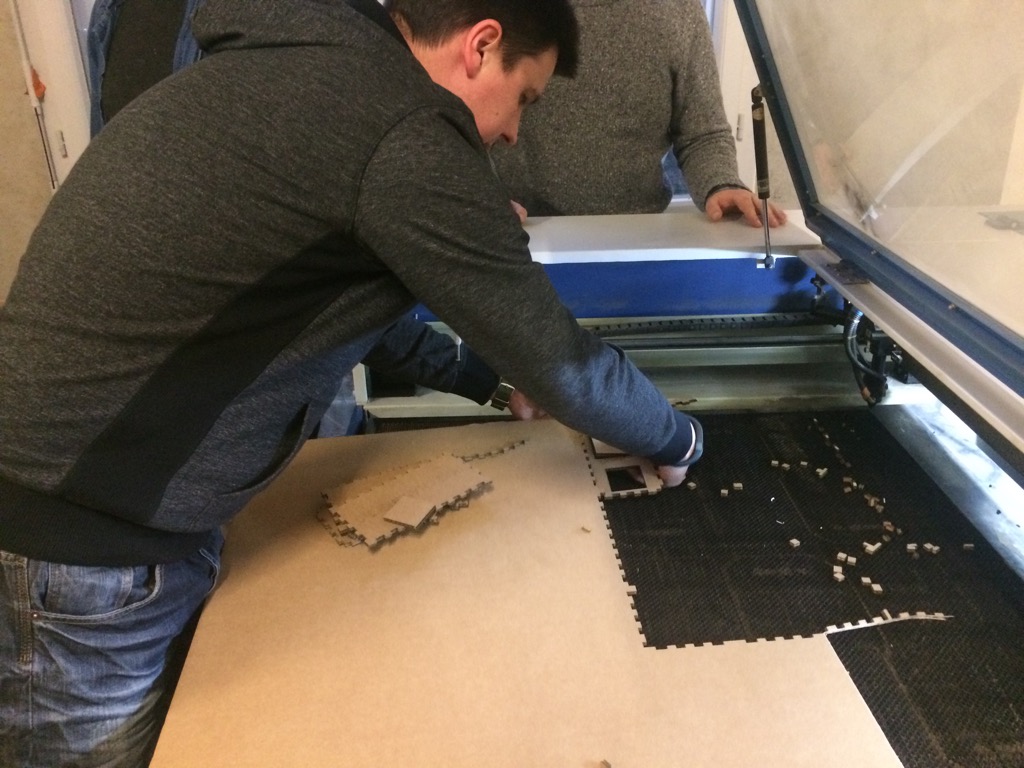
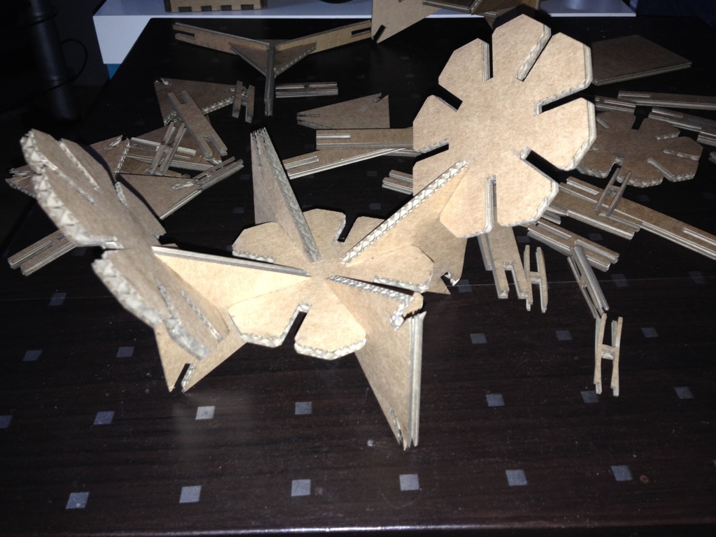
Before starting work on my press-fit I cut models generated last week. Here is the result. So first try was good! :)
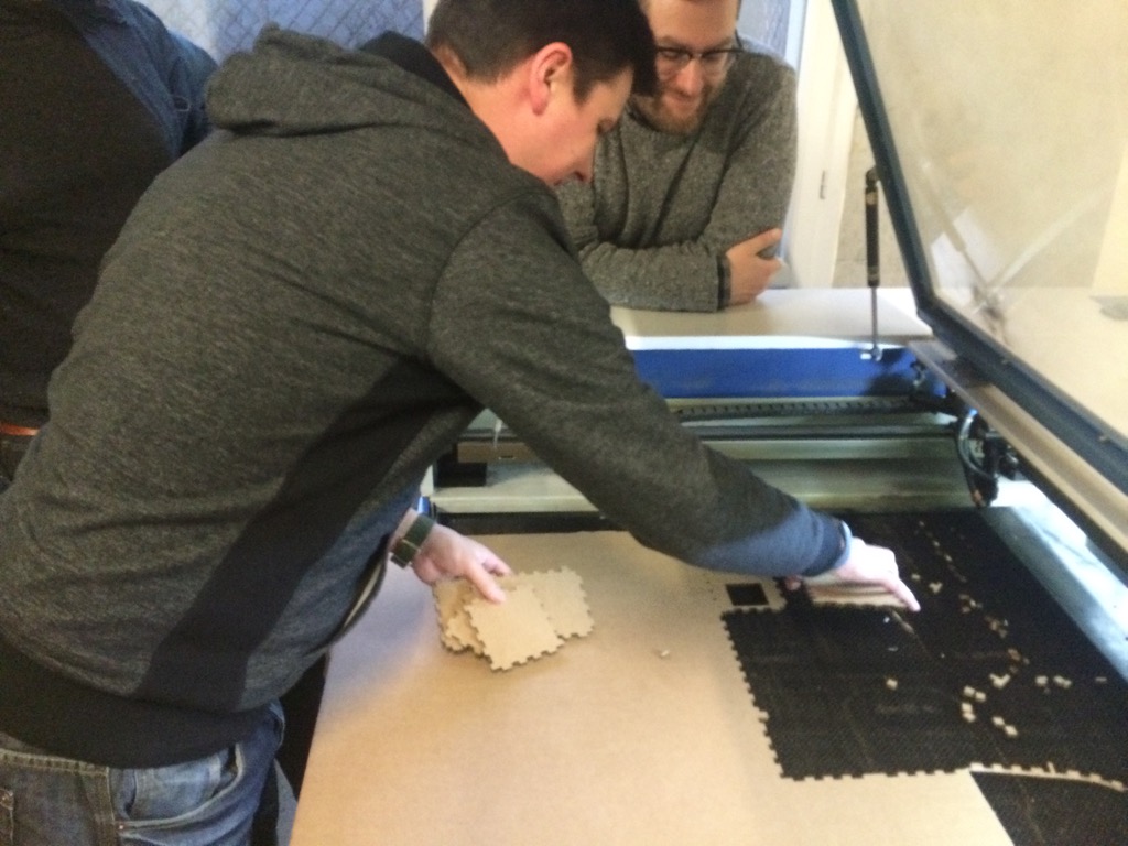
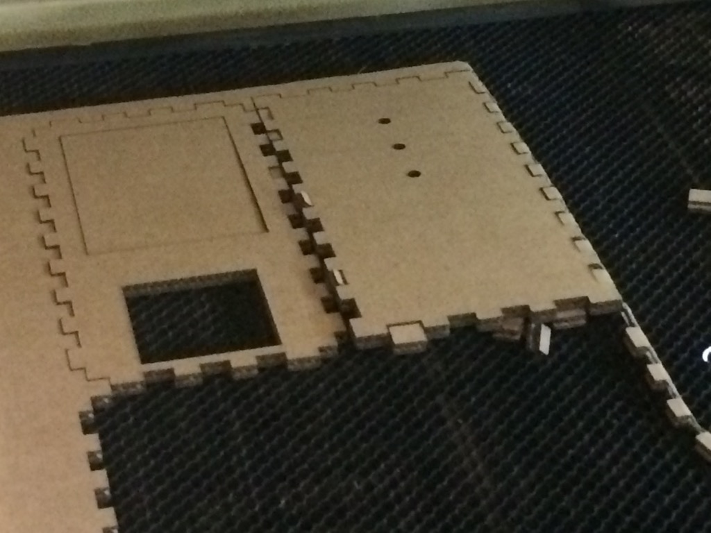
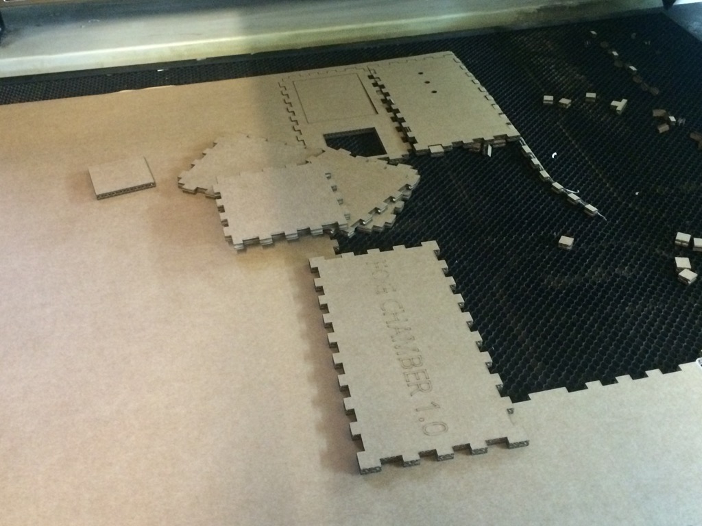
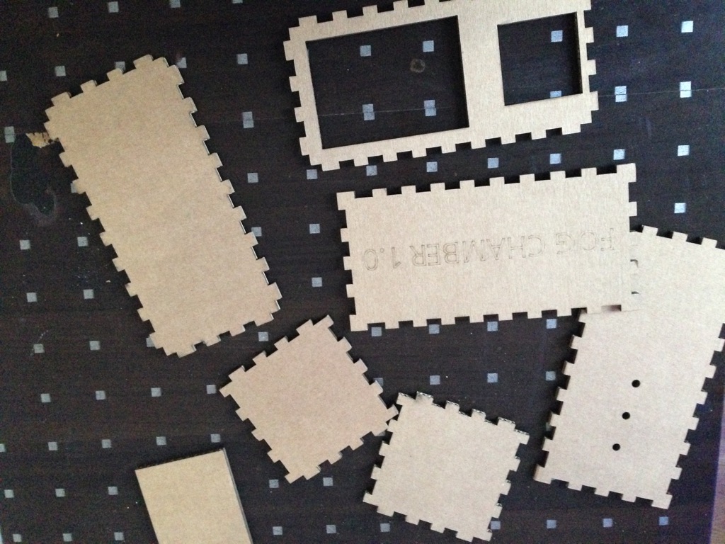
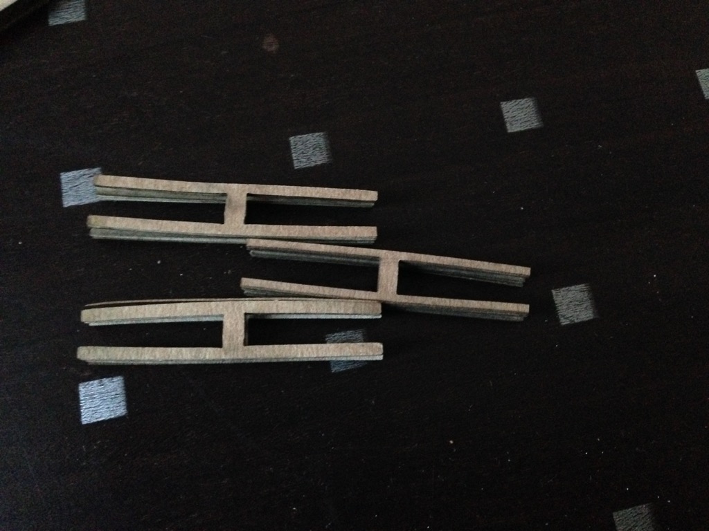
In pieces
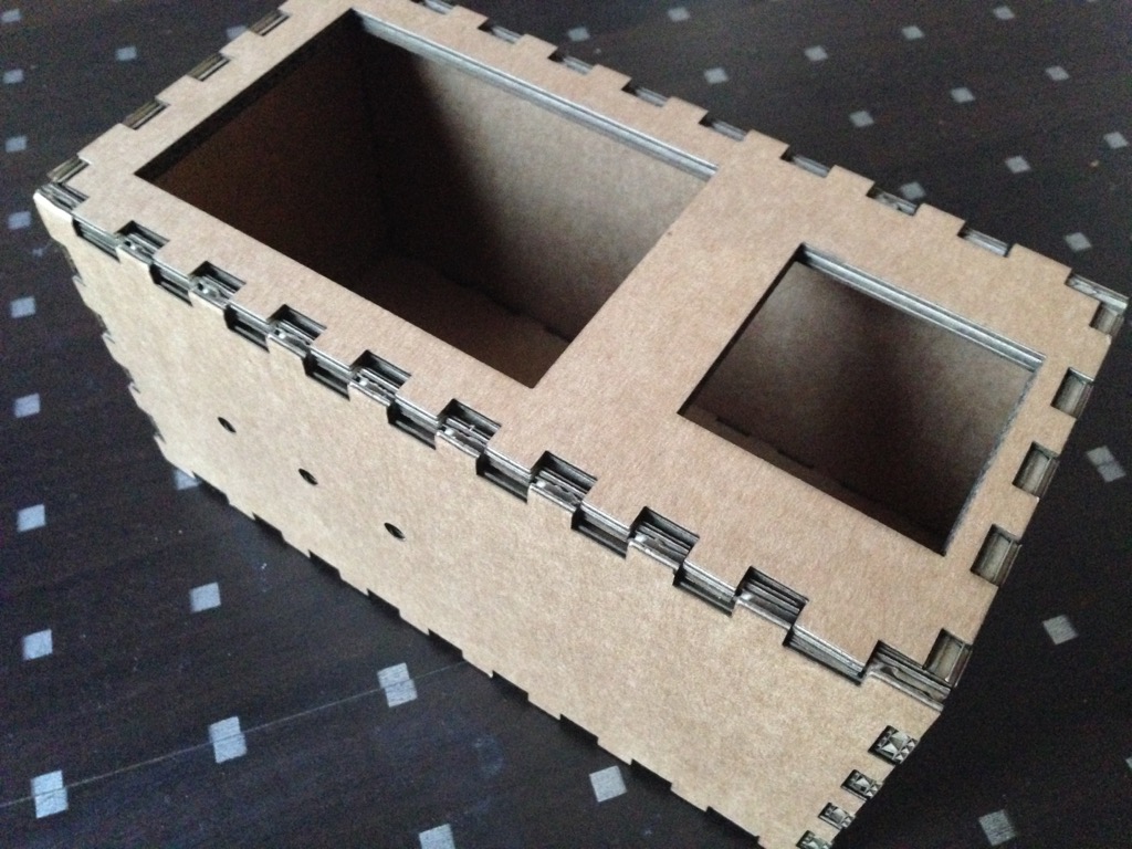
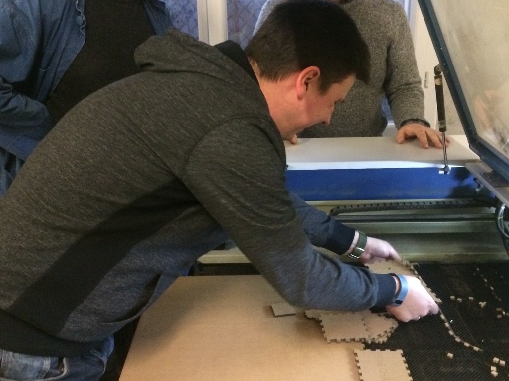
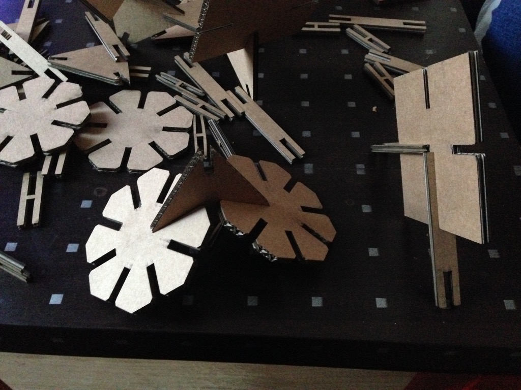
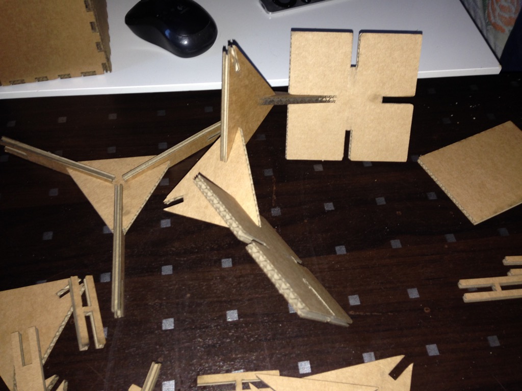
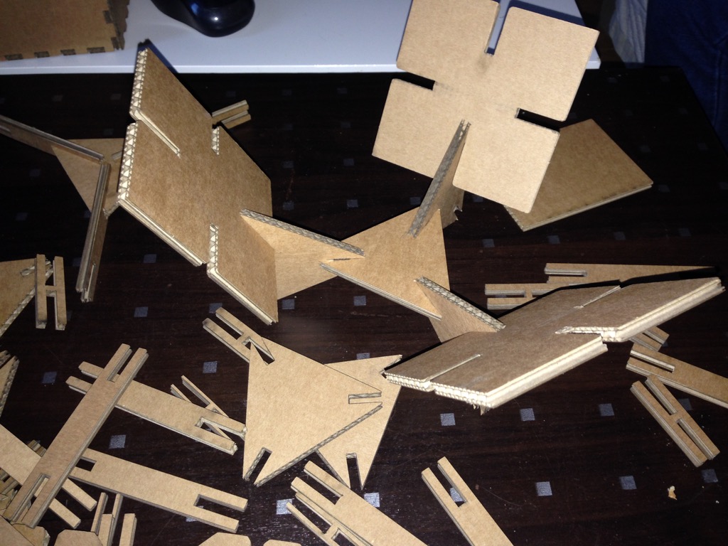
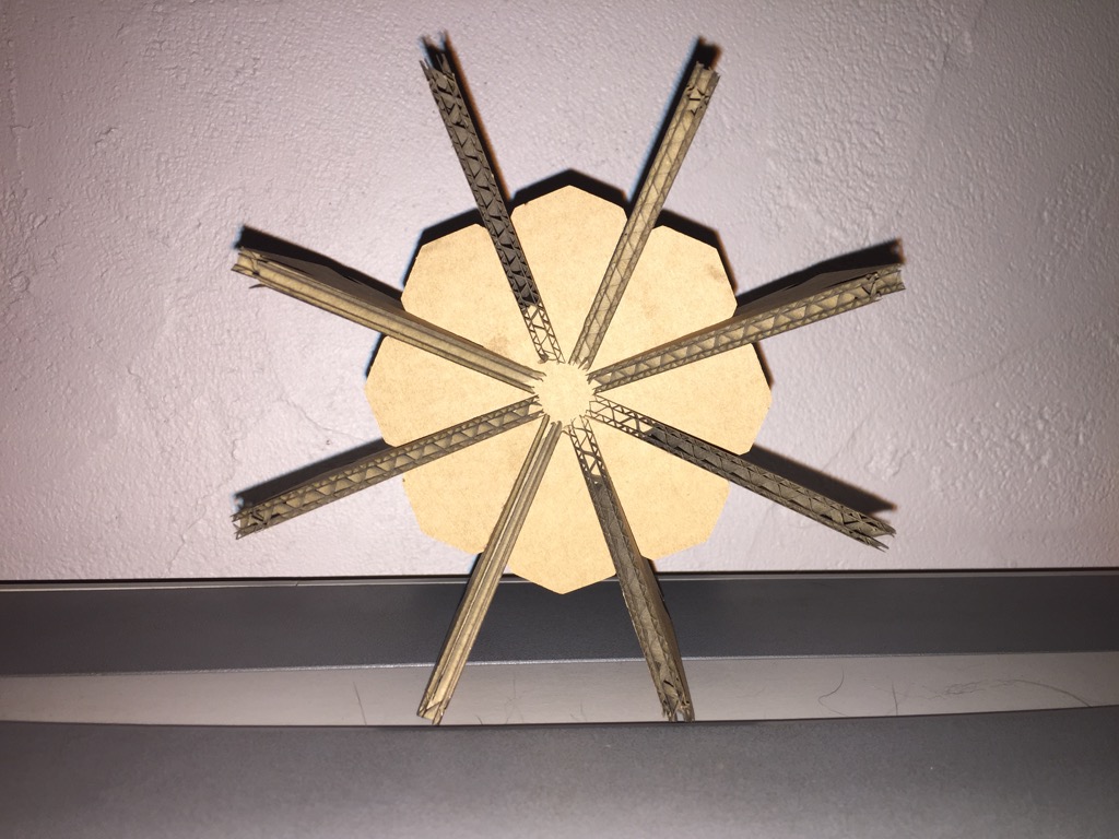
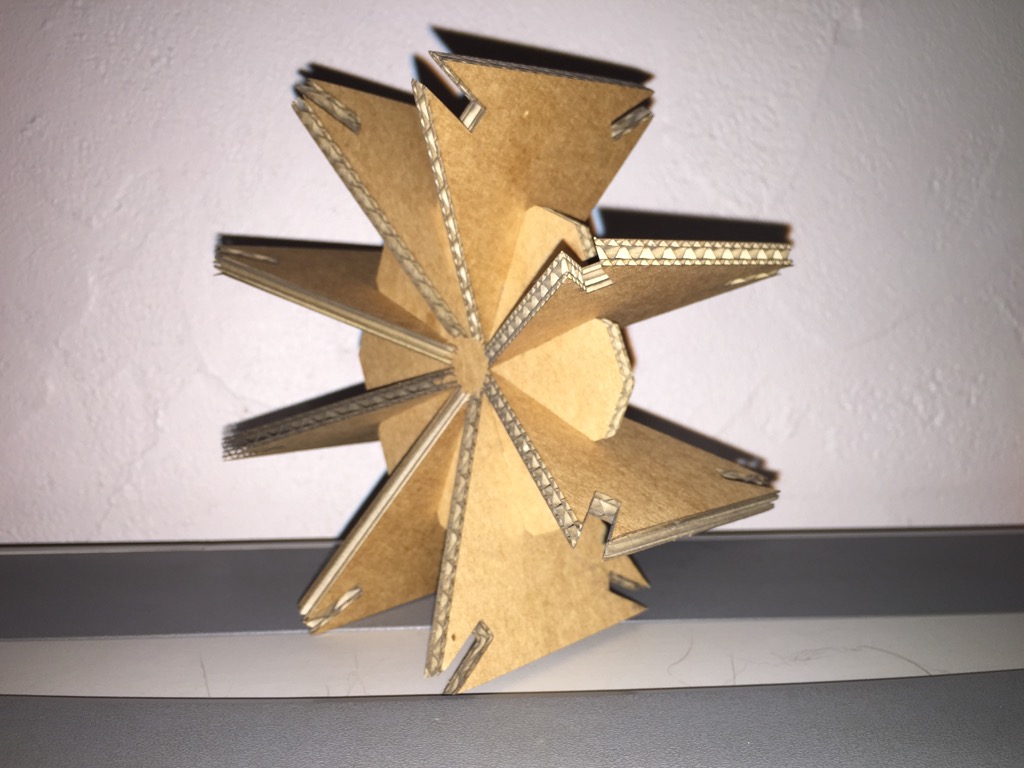
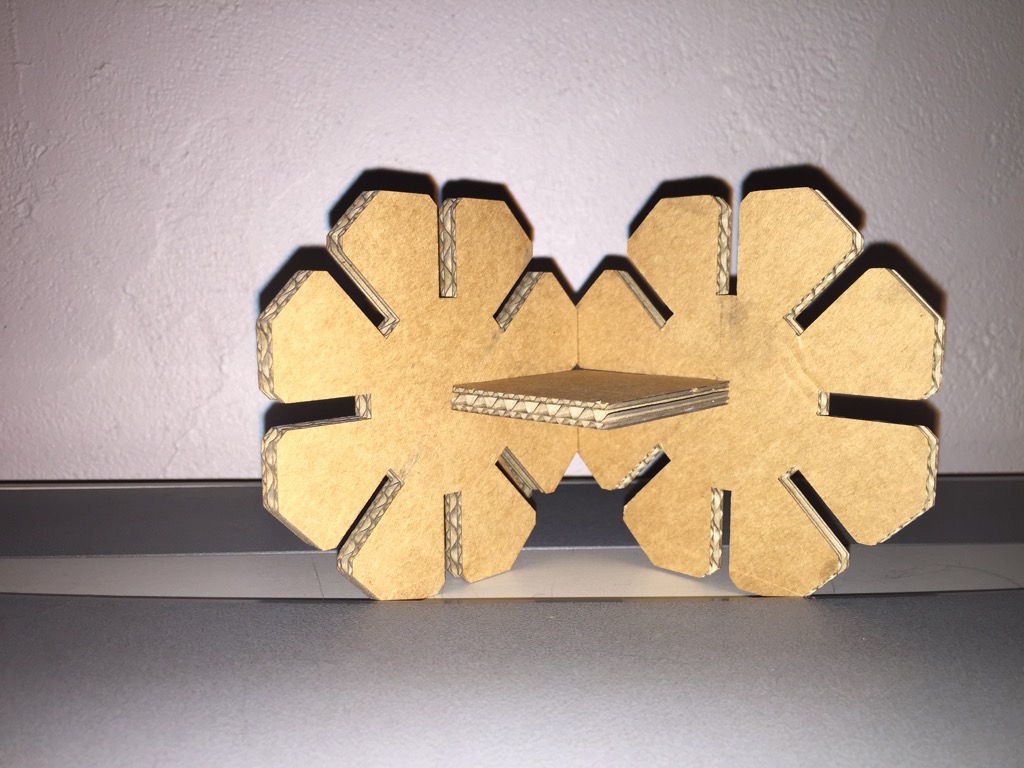
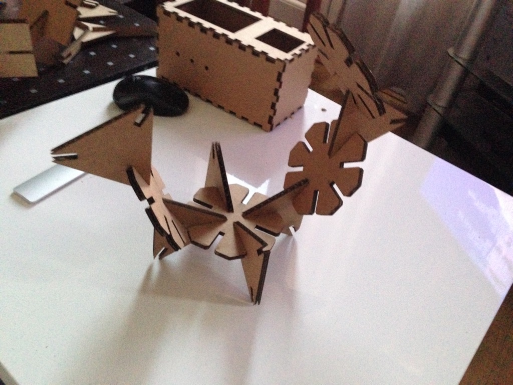
How it looks like connected
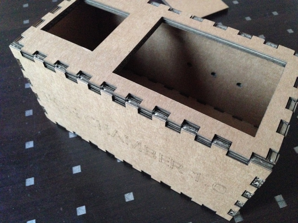
And from another side
Let now pass to KIT production
I started to use Antimony 3D tool. In fact it is really cool tool but because of little community (or hidden one :) ) I passed a lot of time on simple questions... Like why I can not export to "stl"...
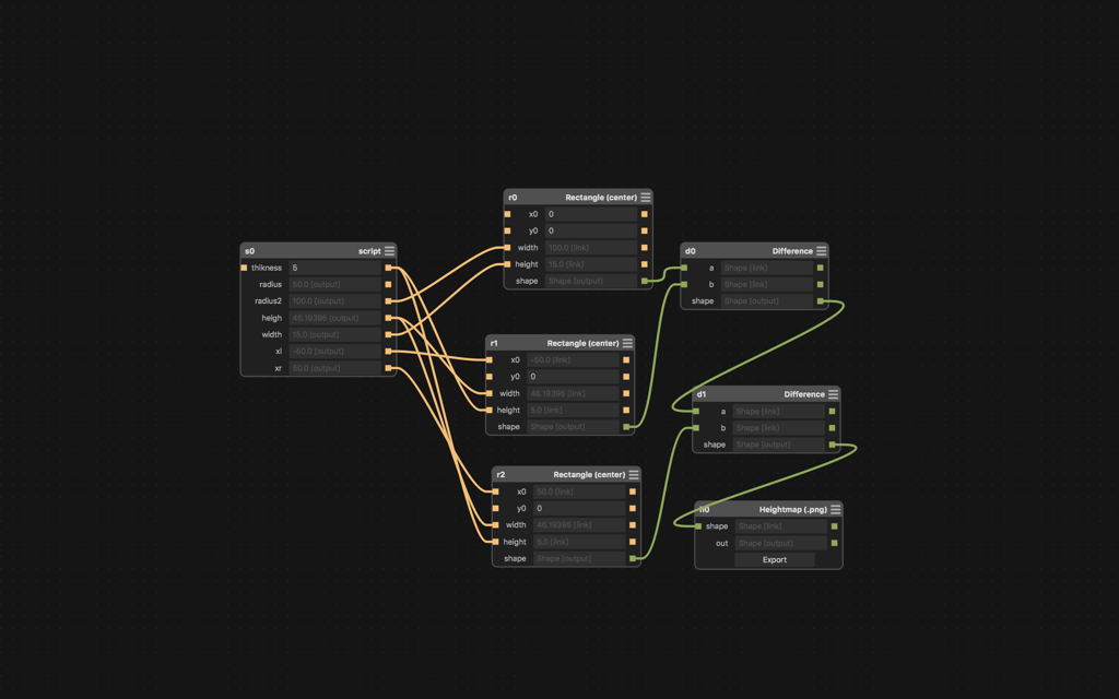
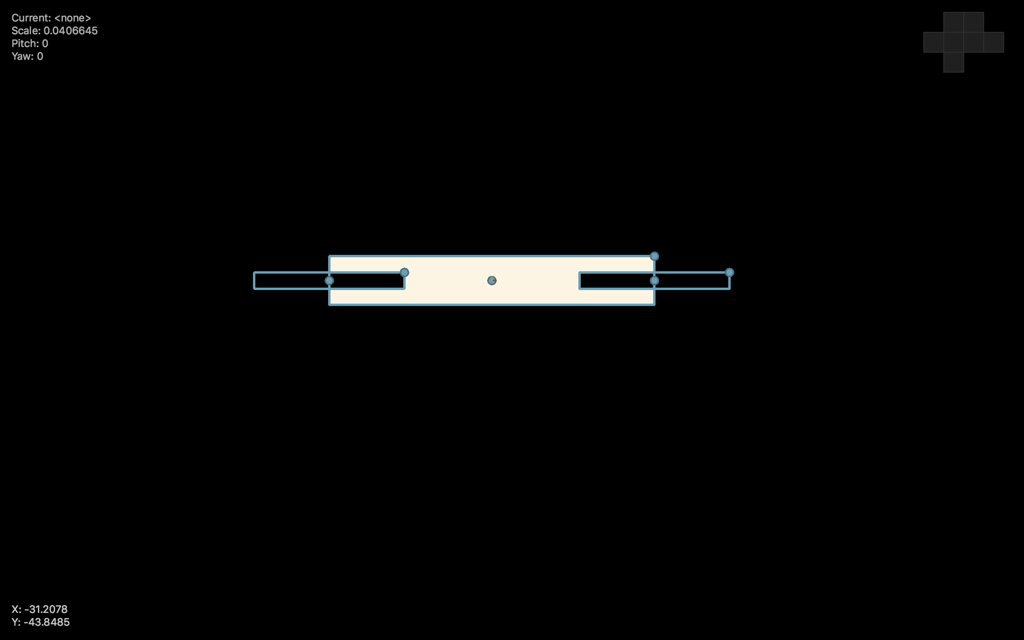
So let try to see Antimony files. At the beginning I did first test not really optimized. So my first try looks like this..
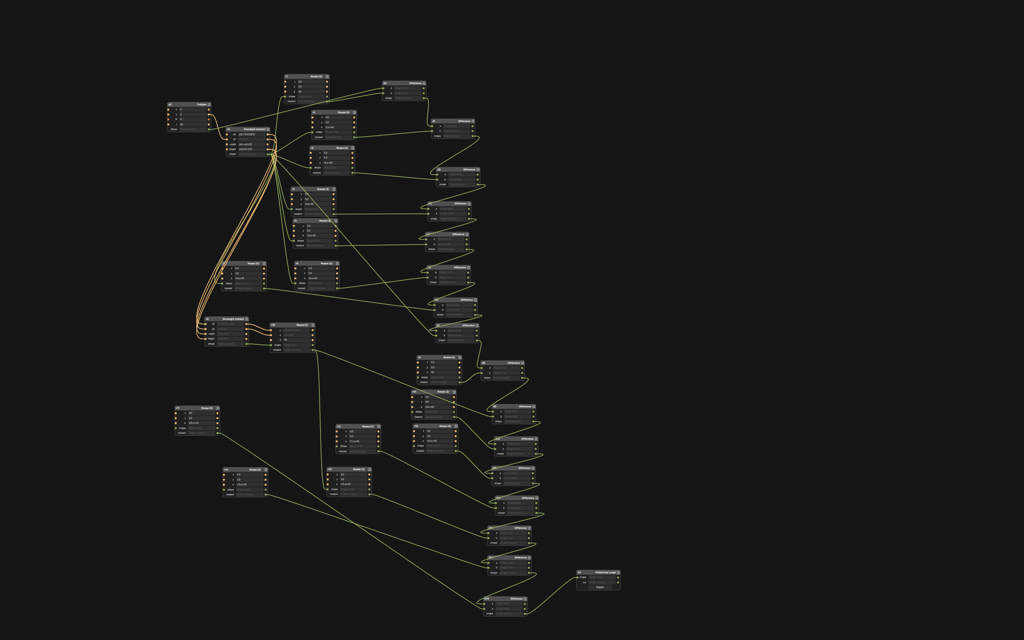
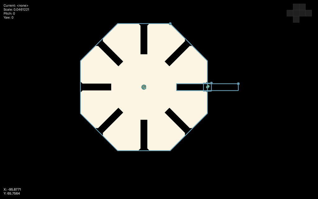
Source file is available here
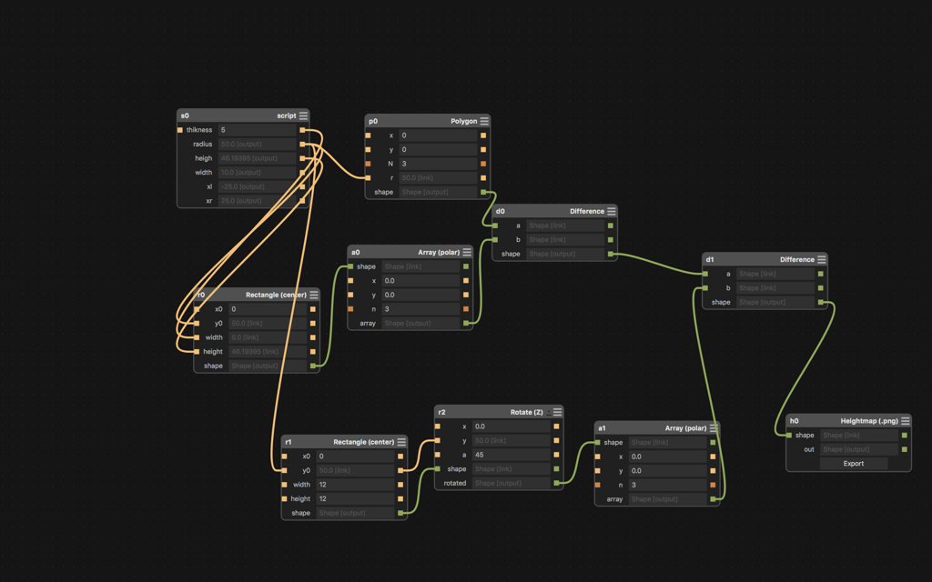
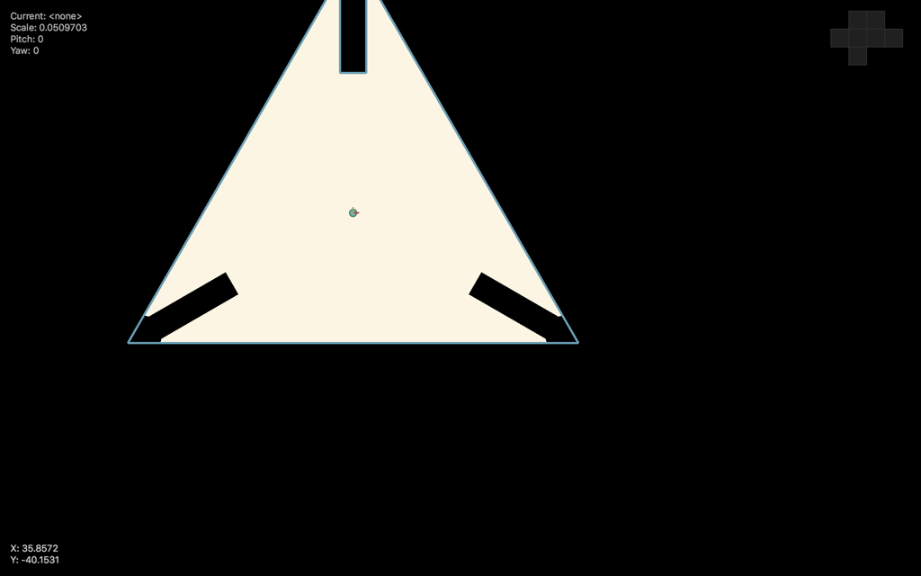
So let optimize it. I found the Array node :-). Looks much better. As well I added the script node that count all parameters before I use them. Now it is parametrized.
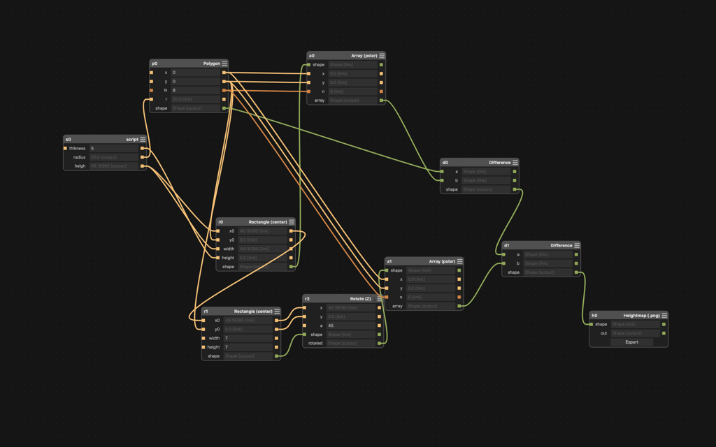
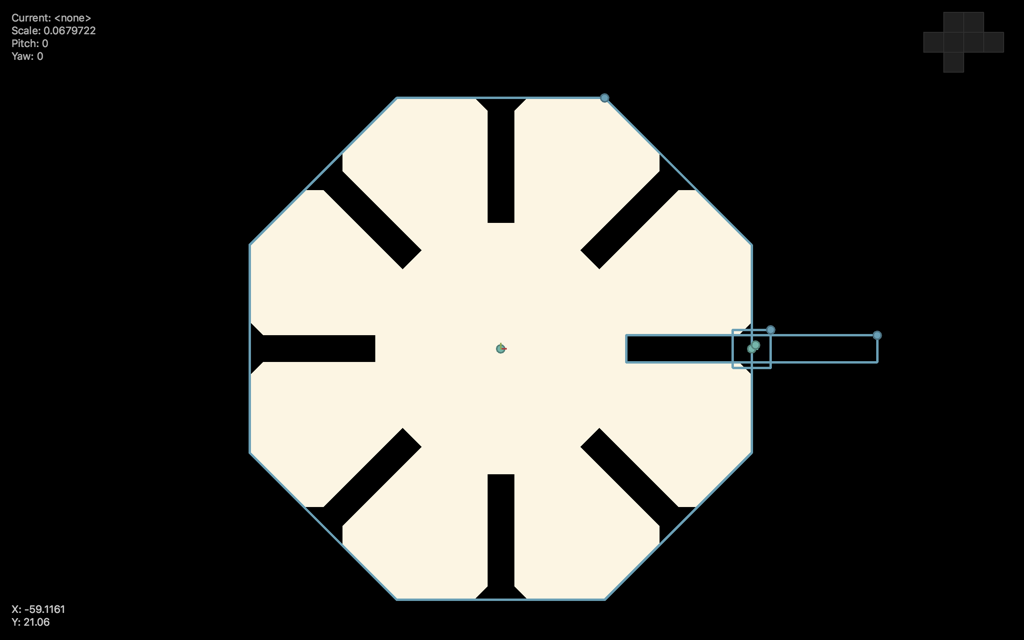
Source file is available here
Let create some more elements. Linker that links directly.
Source file is available here
Source file is available here
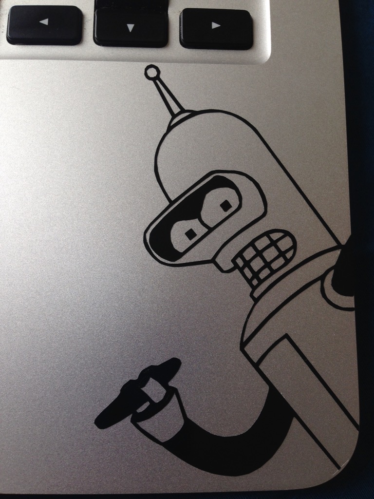
And it is ready. That's how it is looks like and can be used.
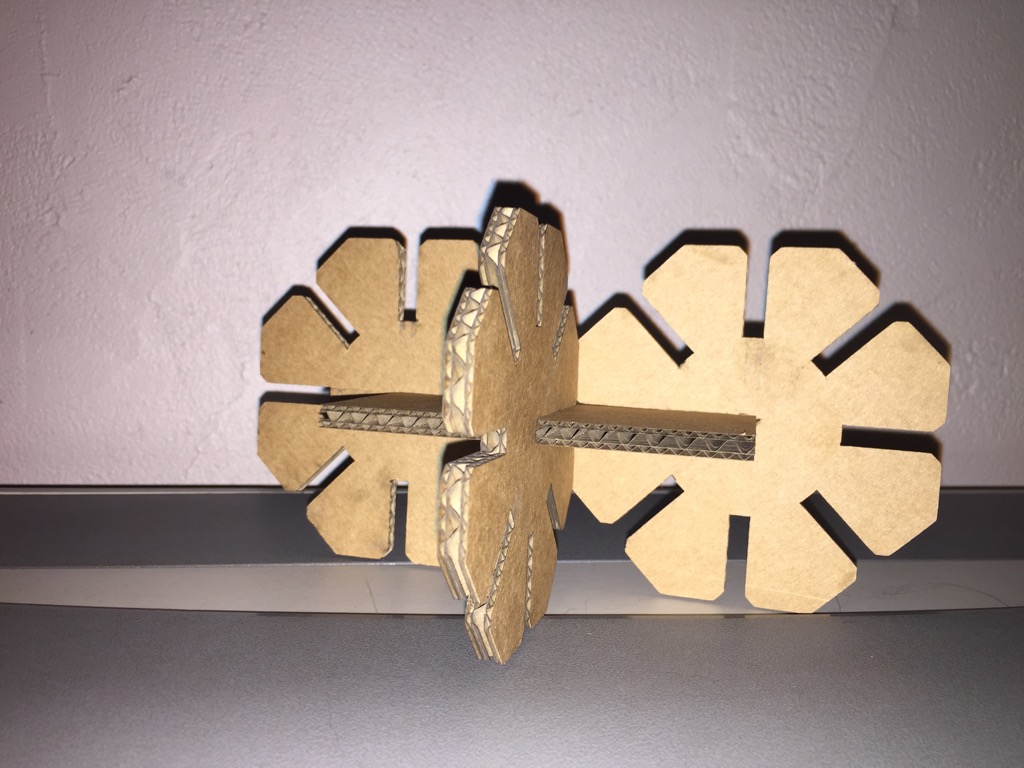
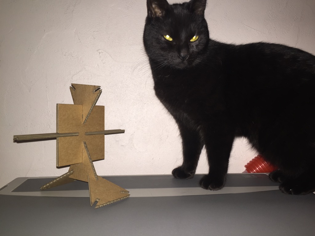
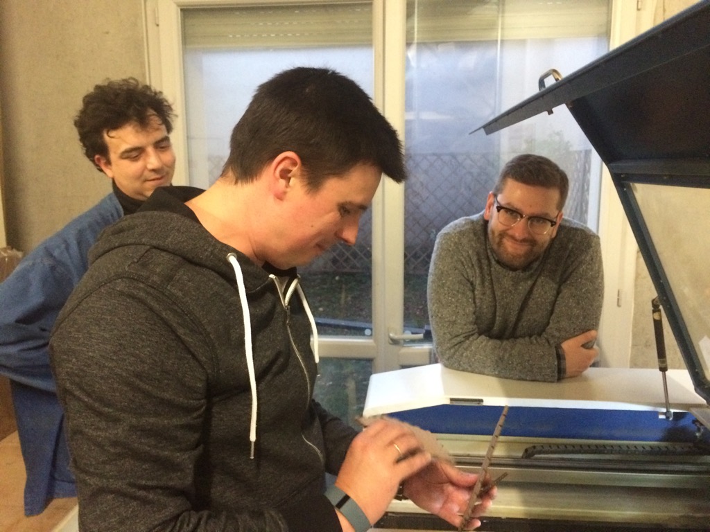
Somebody more interested in it
Some errors during print (too small)
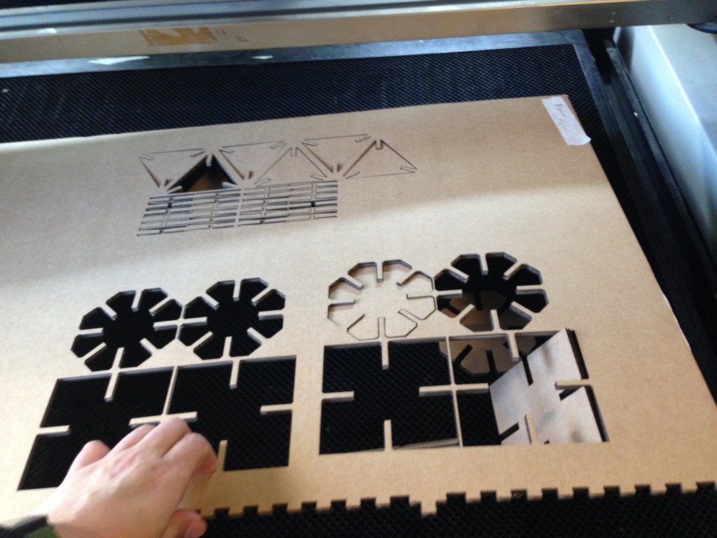
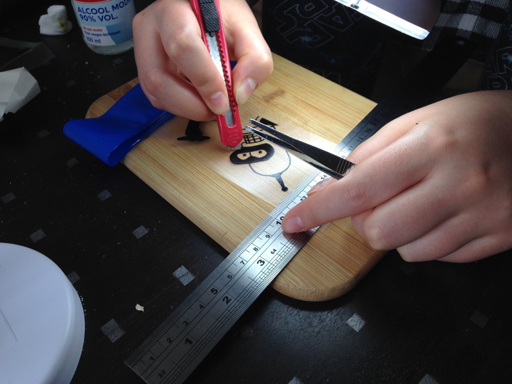
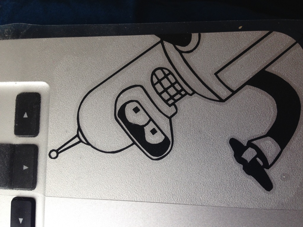
It was produced like this
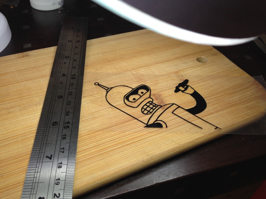
Something special :)
Workflow
Step1. Antimony png
In this step I did the antimony file and generated PNG on output.
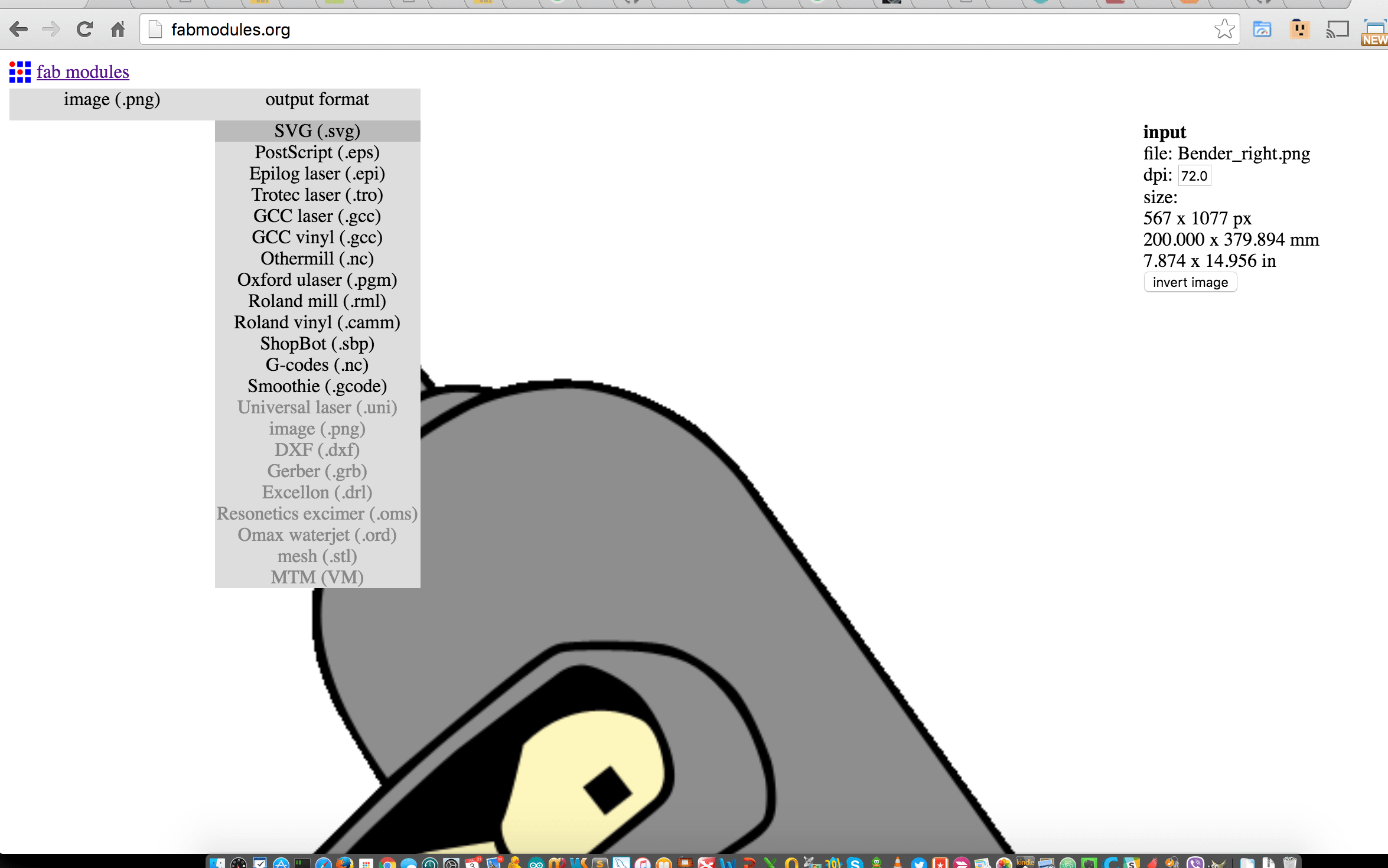
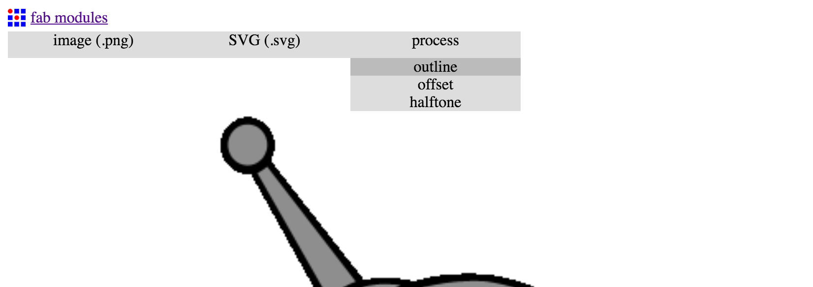
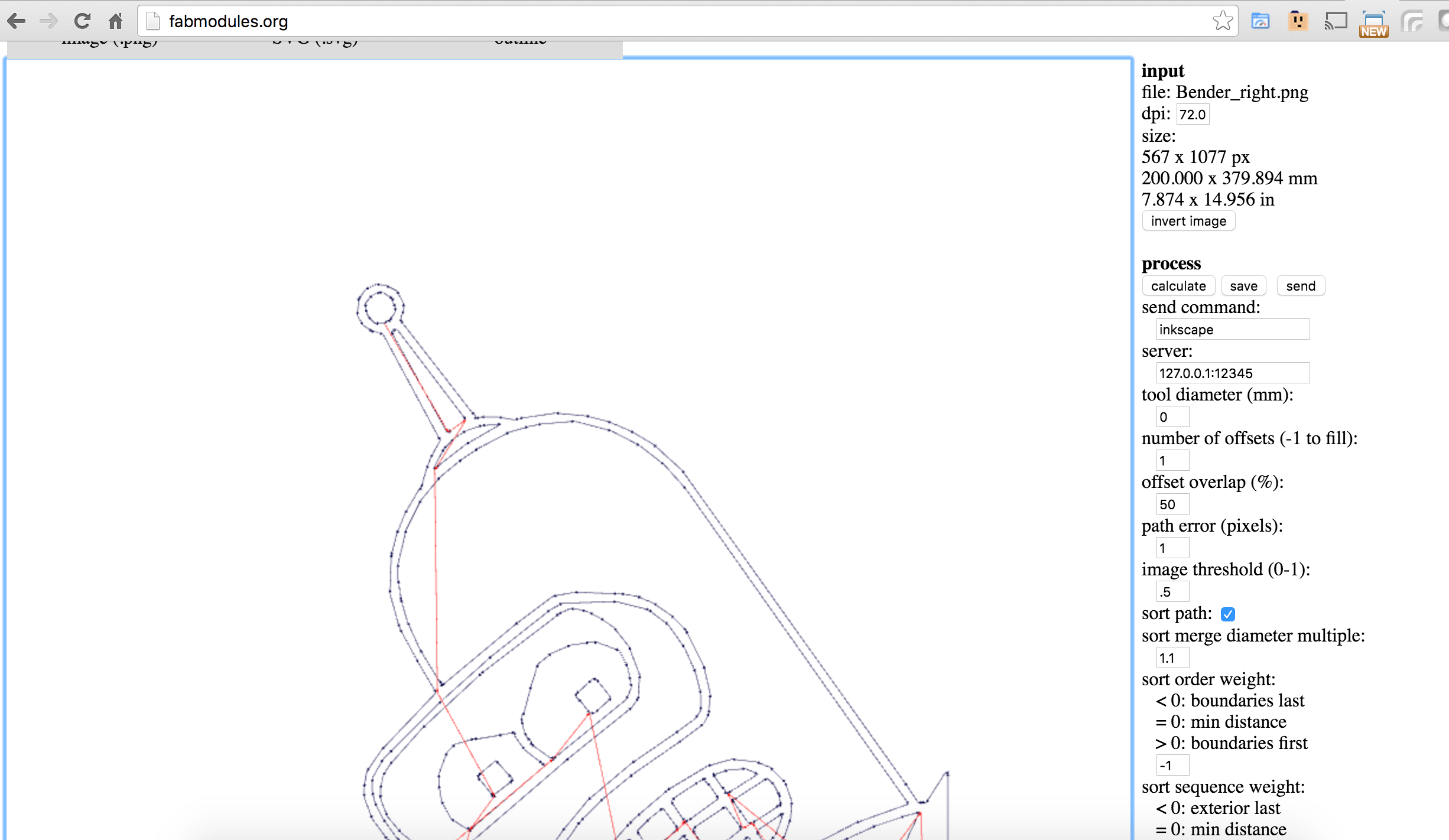
Step2. Inkscape png to vector
We take Inkscape. Load the png file. Then we use bitmap path to create vector from raster image. Then we export it into the dxf file (Autocad DXF format)
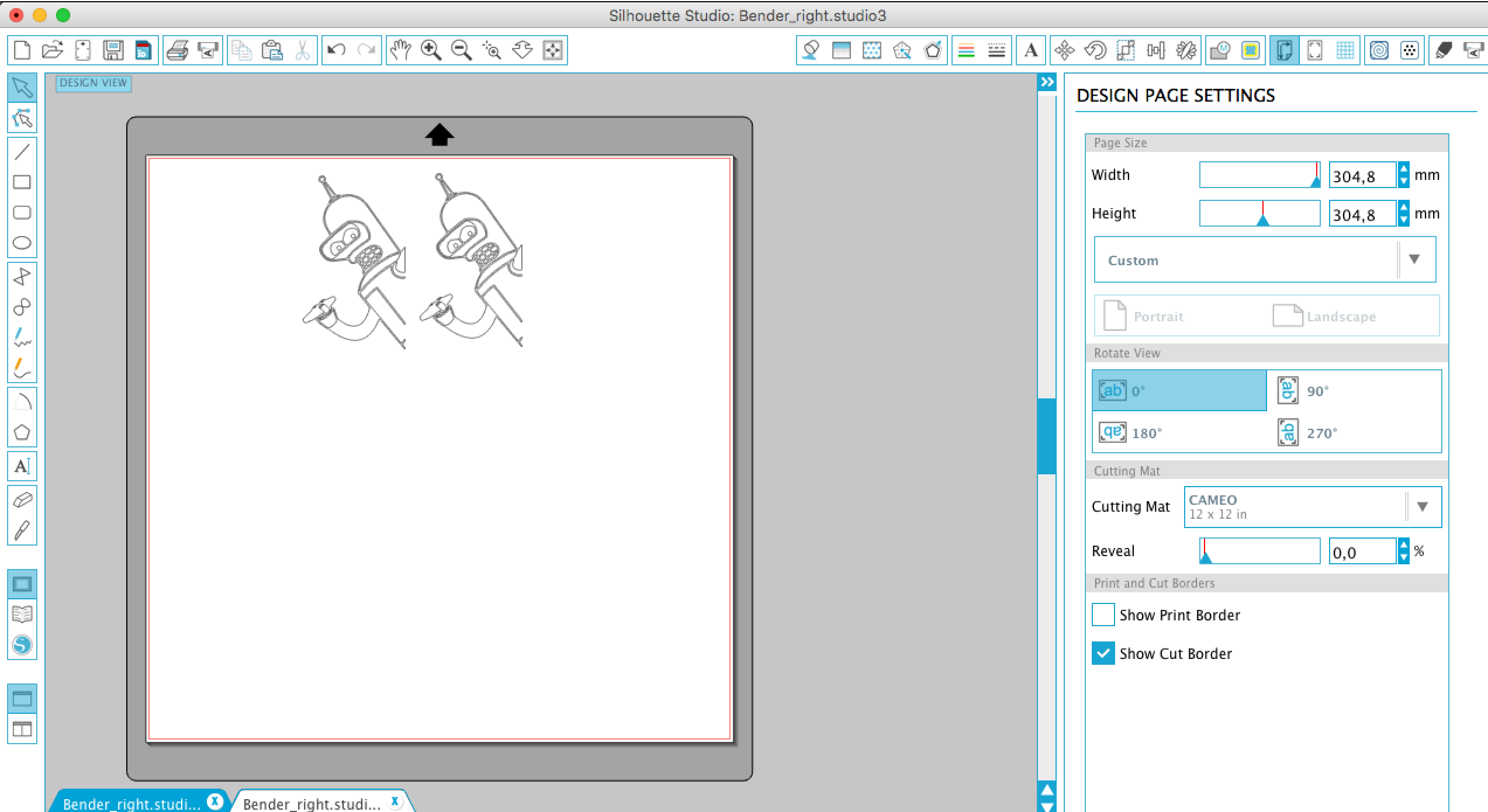
Step3. Rhino dxf to dwg
Rhino import the DXF file (be careful with same sizes as in previous step. Keep mm everywhere). Check the size, duplicate object and place it on the field. Export to DWG format that accept laser cut machine.
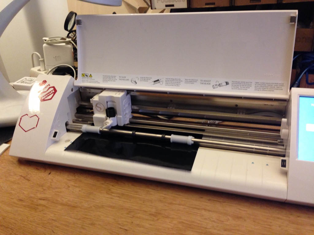
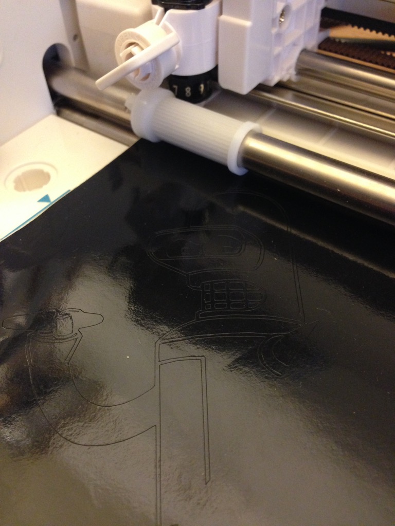
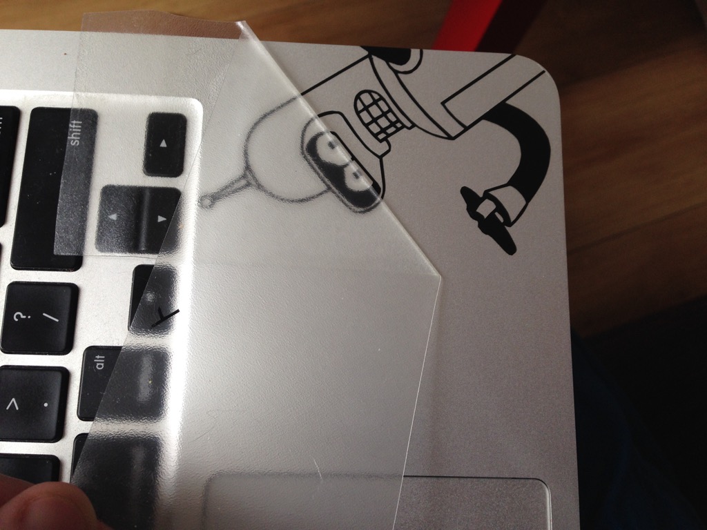
Step4. Print!
Bring the file on USB key to machine and use the standard process of printing this file.
My conclusion
Antimony is a cool tool. It can be very useful for quick parametric 2D or 3D design. And I will continue use it. It permit, when you have some experience with it, produce really fast results. But limitation about format requires to use different tools around to bring result format to be useful. (At least for 2D models). And the video of how machine works. For the first time it is impressive...