I2C network
In my final project, very probably I will use the MAX30100 "Pulse Oximeter and Heart-Rate Sensor IC ". After reading the data-sheet of the chip I found that this sensor communicate via I2C compatible protocol. So I think the best way for me is to start to study the I2C connection protocol during this week.
Some theory
I²C (Inter-Integrated Circuit) pronounced I-squared-C is protocol initially developed by Philips Semiconductors company. It is quiet simple in realization protocol uses 2 wires to communicate and + 2 (VCC + GND) wires. Because of licensing - a lot of devices uses this protocol but name it differently. For example in Arduino library it named "wire protocol", in Max30100 data-sheet - it named "I2C compatible proprietary protocol". But it is always the same one.
Addressing of nodes in this protocol is limited by 7 bit starting message. So 127 nodes. In reality number of nodes is 112 because few addresses defined as reserved. In newest version of protocol 10 bits may be used for addressing so number of devices is increased up to 1024. Speed in this protocol also varied depending of version between 100kbit/s (10kbit/s in low speed mode) and 1..3Mbit/s in recent versions of protocol.
Physical layer if communication is two wires (SDA, SCL) are connected to all nodes and using the pull-up resistors (usually 1Kohm) to VCC. So the IDLE state is always HIGH. When we pull up them to ground we define signal of action. SCL is the synchronization clock wire and used to define ticks of sending bits. Start condition is the LOW signal on data wire when the SCL is HIGH.
Communication is always provoked by master. And only master manage the SCL signal. When communication starts - master define address of node he need to communicate and the communication method (read or write). In case of write (0) - master will send data to slave node, and in case of read (1) will wait that slave node send data to master.
For the acknowledge of received messages (as well for the acknowledge the presence of address when the slave node understood that master will talk to it) slave need to take SDA link LOW during the HIGH phase on SDC link in 9th bit in communication (special bit to acknowledge receive data). As well slave may pull-down SDC before 9th bit - in case if it need some more time to process received byte. That method shows that not always the SDC controlled by master and may be used by slaves to control speed of communication)
Some practice
I decided to take 2 arduino boards and make a simple communication between them. One of two arduino boards will play role of master and will send messages ON and OFF to slave node. Slave node will apply ON or OFF state on the LED and we will see that it change it state.
So below is the code for the slave node. This node has address 8. It uses kind of interruption in arduino style code in Wire library. And on event "onReceive" - subroutine will be execute that will get message from the IIC communication and compare it to rules and change state of LED. As well message is sent to serial that we can see it for debug purpose (when we connect to USB slave node - we can read it)
#include <Wire.h>
String getString;
int led = 13;

void setup() {
  Wire.begin(8);
  Wire.onReceive(receiveEvent);
  Serial.begin(9600);
  pinMode(led, OUTPUT);
  digitalWrite(13, HIGH);
}

void loop() {
  delay(100);
}

void receiveEvent(int howMany) {
  getString="";
  while (1 < Wire.available()) {
    char c = Wire.read();
    getString +=c;
  }

  Serial.print("Got message: ");
  Serial.println(getString);

  if ( getString == "OFF"){
    digitalWrite(led, LOW);
  }
  if ( getString == "ON"){
    digitalWrite(led, HIGH);
  }

  int x = Wire.read();
  Serial.print("Message number: ");
  Serial.println(x);
}
And next code is the sketch for master node. It is more simple one as it open communication to node with address 8. Then it send there one of two messages (ON or OFF) and byte that show the message number. It also interesting to check if we disconnect wire and cut the communication - if the message will be lost, or communication will be hanged until the node arrive. (TBD).
#include <Wire.h>

void setup() {
  Wire.begin(12);
}

byte x = 0;

void loop() {
  delay(500);
  Wire.beginTransmission(8);
  Wire.write("ON");
  Wire.write(x);
  Wire.endTransmission();

  x++;
  delay(500);
  Wire.beginTransmission(8);
  Wire.write("OFF");
  Wire.write(x);
  Wire.endTransmission();
  x++;
}
Connection is simple - pins 4 and 5 are interconnected between the arduino (not required to cross them as each node connect always to SDA and SCL wire). Also GND and VCC5v are connected to avoid to power second arduino board separately.

Here you can see how it works. Slave arduino board is not connected to USB but just to master via 4 wires (VCC-5V, GND, SDA, SCL).
Let use some boards
Now, after some tests with Arduino I decided to re-execute I2C network communication by using the ATTiny 44/45 controllers.
I will do my assignment inside the idea of my Soil moisture sub-project . So the idea is to have one master node, that provide power for every nodes, and that act as a master
in the I2C communication (in schema when master requests for informational packets from slaves).
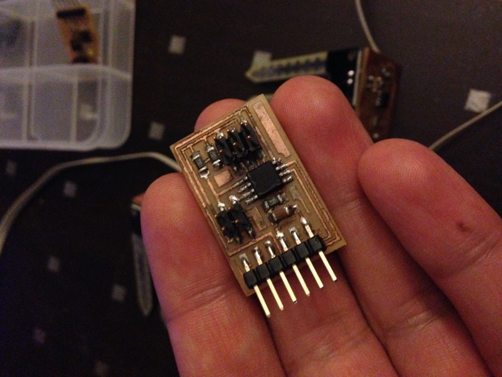
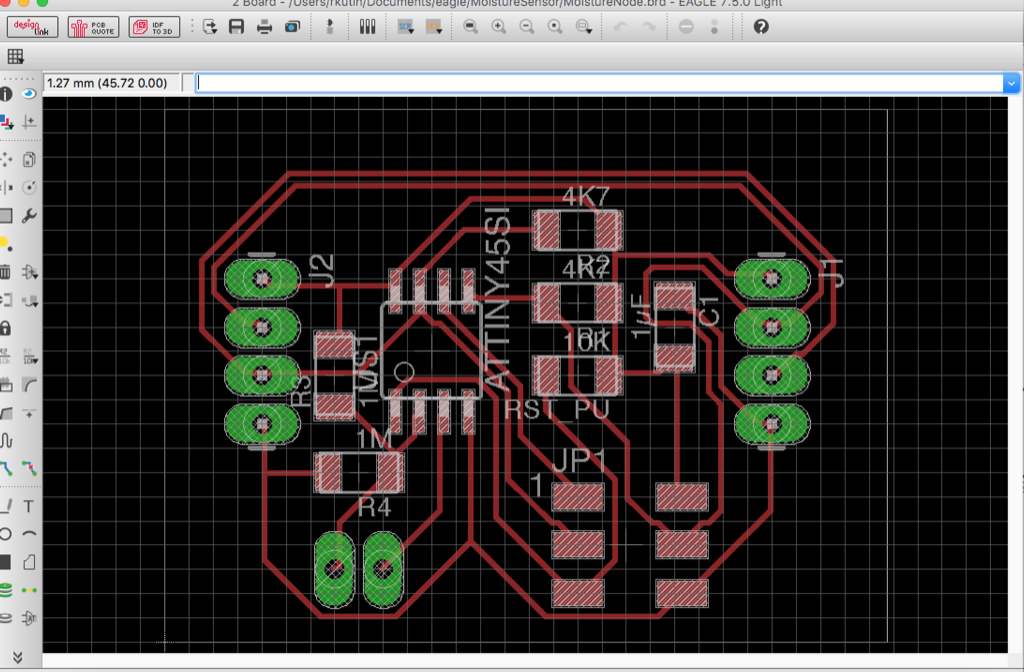
As the master board I took an existing board (for this assignment) from the week schedule materials. This board contains attiny45 chip, I2C header and the FTDI header, so I can collect data directly on screen for this assignment.
Below is the board image from the week materials.

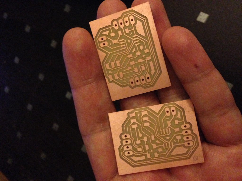
So I milled it and soldered.
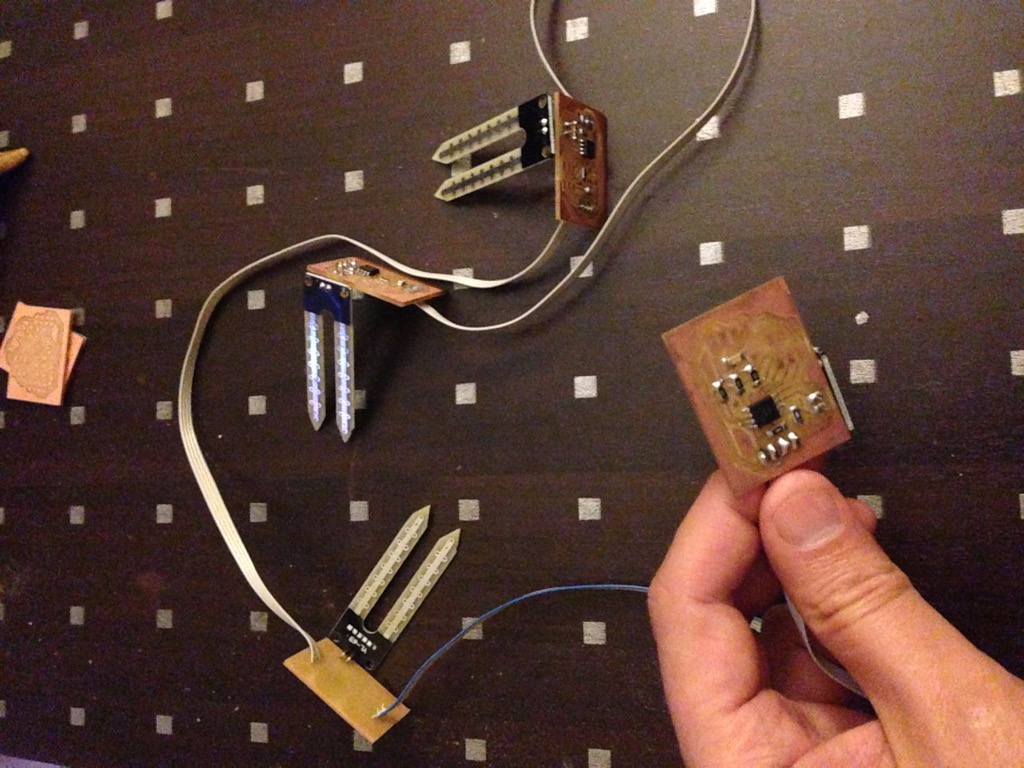
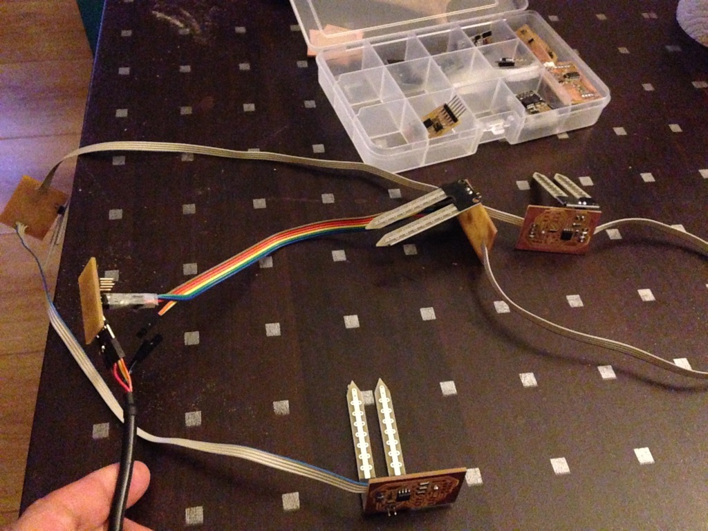
For the slave nodes - I will use my board from "Soil moisture sensors".

As well nodes were milled and soldered. Nodes are interconnected by wires directly soldered to each side of node (connector in / out to be able add to serial new nodes)
Remark: In fact, when I build these nodes I did not fully understood the selection for the pull-up resisors values. So I took values from the week materials (10KOhm on each node and on master). In example for
the week it looks as a working solution. But in reality this subject is more complex.
The value for the pull-up resistors change the shape of the signal. Bigger value increase time for pull-up signal and change the shape for the signal.
Also, we need to take in account that each node connected to same BUS (vcc, ground and two signals, SDA and SCL) and pull-up resisors are beween the common bus wires (common vcc and common sda and scl). In this logic we need
to cound global resistance. So the example from the week for 3 nodes and each time 10KOhm resistance as a pull-up resistor on each node will give us pull-up value to about 3.3KOhm...
Exist a document that explain how to calculate value for pull-up resistance. It depends of speed of I2C bus (exist 2 standards) and there is a table of minimal and maximal values for pull-up resisors...
It's funny, but common resistance is enter into the range. And even adding some nodes will continue be in correct range. I estimated it about 6 nodes - then the value will be out of range.
Most popular value for the resitance is 4K7Ohm. So when I did my next versions - I already took this knowledge in account. But in current version, I just did not soldered resistance where I don't need them.
All slave nodes are interconnected by wires (soldered to a boards).
Now let start programming them.
I started by simple. I tried to use Wire.h and quicly detected that it will not be so simple. The size of the commpiled version very quicly overload the memory of the attiny45/44 controller. Initial reflext was to use the Atmega controller instead of
attiny... So I build a prototype with satshakit. (The moment I have discovered that satshakit do not have output VCC and GND...)
I found libraries: Attiny core libraries that countains TinyWireM.h - for the master node and TinyWireS.h for the slave node. Usage is quet simple, but we need to take care about timing. These libraries are tested and works for 8MHz for attiny44/45. I ensured that fuses are correct before I do my tests.
Now I do simple code to check communication.
Slave node: Each node will have own address and will do simple action on this stage: when it will received request for data - it will do +1 to internal counter and return it back. As request will ask only for
1 byte (at least on this stage), I will return value between 0 and 255 (integer counter).
Remark: When I will program my nodes, I need to take care to change address of node each time I program a new one. NB: Need to just make a notice by pen on each node with it's address.
Below is the code that will be applied on each node:
    #include <TinyWireS.h>

    #define I2C_SLAVE_ADDRESS 0x13 // Address of the node (they are between 0x11..0x14)
    int i=0;

    void setup()
    {
        TinyWireS.begin(I2C_SLAVE_ADDRESS); // join i2c network as a slave
        TinyWireS.onRequest(requestEvent);
    }

    void loop()
    {
        // This needs to be here
        TinyWireS_stop_check();
    }

    // Gets called when the ATtiny receives an i2c request
    void requestEvent()
    {
        TinyWireS.send(i);
        i++;
    }
Master node: This node will do 2 things - it will open Serial communication to my computer and it will in loop ask each node for 1 byte of data. Received byte will be sent as a character to serial link. On
my computer I will start a serial communication app that will show output.
Below is the code:
#include <TinyWireM.h>
#include <SoftwareSerial.h>

SoftwareSerial mySerial(PB4, PB3);

void setup()
{
    TinyWireM.begin(); // join i2c network as master
    mySerial.begin(9600);
    mySerial.println("Hello from board"); // Just a message to see beginning of work
}

void loop()
{
   TinyWireM.requestFrom(0x11, 1);          // Ask node with address 0x11 for 1 byte
   while(TinyWireM.available()){            // If something replied - let get bytes
    mySerial.println(TinyWireM.receive());  // We get byte and write it direcly to Serial
   }
   delay(500);

                                            // Let repeat for nodes 0x12, 0x13, 0x14
   TinyWireM.requestFrom(0x12, 1);
   while(TinyWireM.available()){
    mySerial.println(TinyWireM.receive());
   }
   delay(500);

   TinyWireM.requestFrom(0x13, 1);
   while(TinyWireM.available()){
    mySerial.println(TinyWireM.receive());
   }
   delay(500);
   TinyWireM.requestFrom(0x14, 1);
   while(TinyWireM.available()){
    mySerial.println(TinyWireM.receive());
   }
   delay(500);
   mySerial.println("next");                // Just to see in communication next cycle start
}
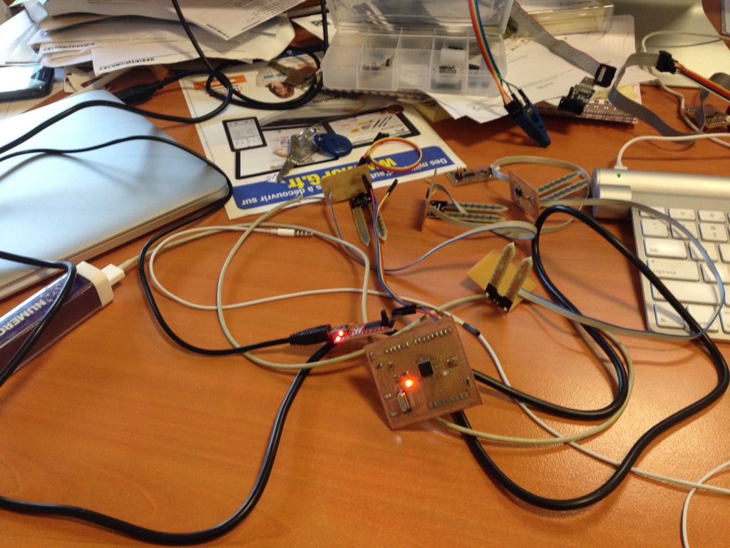
For connection between my computer and master node I will use the FTDI cable (in fact just RX and GND is enough for communication and VCC will power all nodes). Here is the final connection view:
So I see as result - nodes replies each on own step the int i value. And I see that in this I2C communication used 5 nodes (4 slave). On the video we can see the from the master node.