Prepare my 3D model for molding
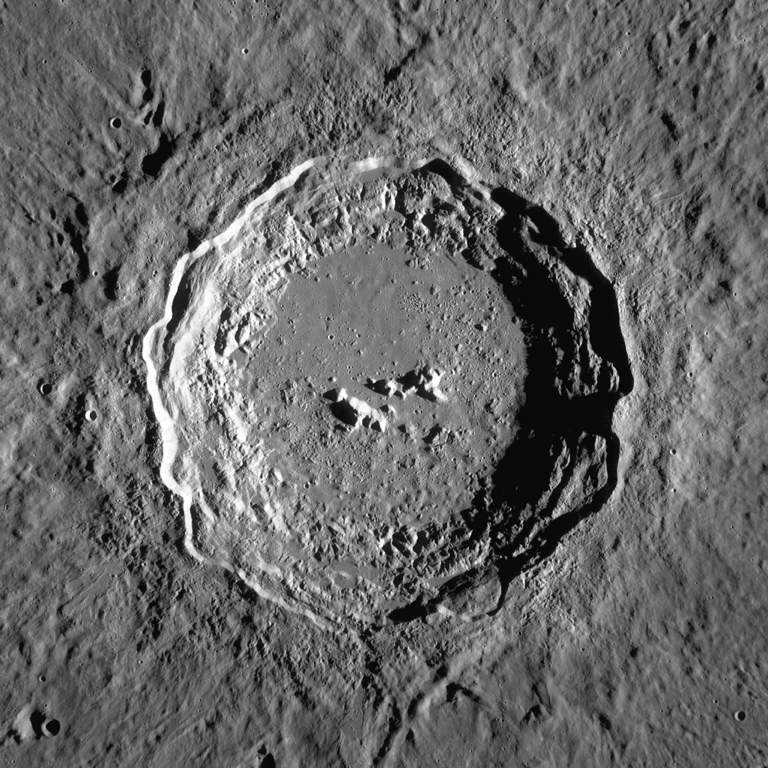
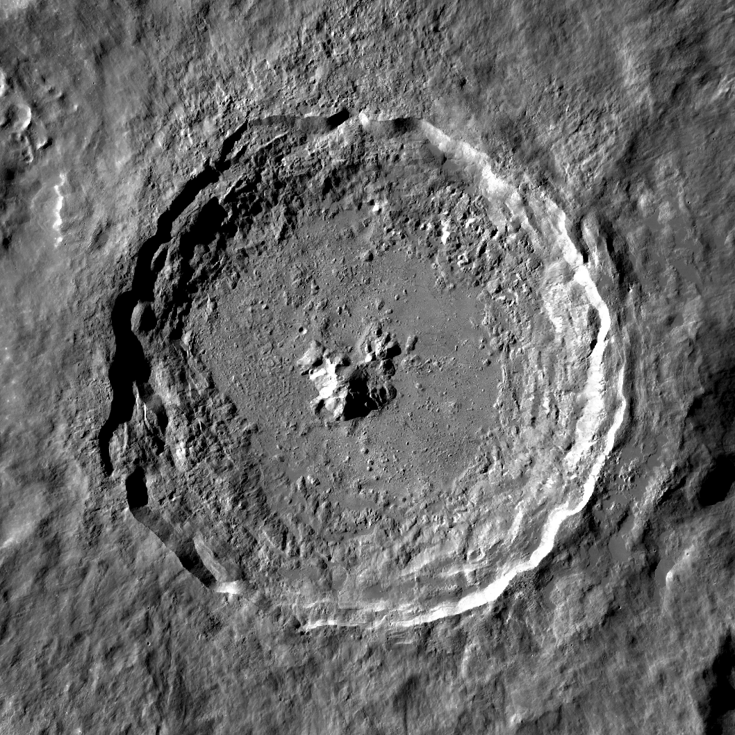
After some research and as for my main project I can not define what kind of molding and casting I may require - I decided to make a molding to create a copy of a crater on the Moon. I took a Copernicus crater as one of mostly known and recognizable crater. As well I tried in parallel to work with images of crater Tycho, just because I saw different quality of images available in the net.
First of all I need to make a 3D model from the photos that I can found in Internet. So let check this out.
I thought about different methods - found a color map with altitudes and write a code that will transform altitudes to STL mesh. And I search for existing library and found png23d application. It can take the png file and using the grasycale transform it to 3D model. So using this software I tried to produce correct result. For example here is one of my try
$ png23d -v -t x -l 32 -w 100 -d 12.8 -o stl copernicus_lro.png 1.stl
Then the result STL file I load into meshlab and try to simplyfy mesh by reducing the edges by applying the "Quadric edge planar decimation" to 10 times less edges. so from 10930831 to 1093083
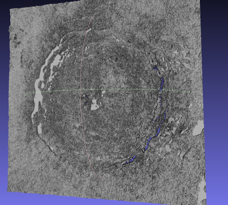
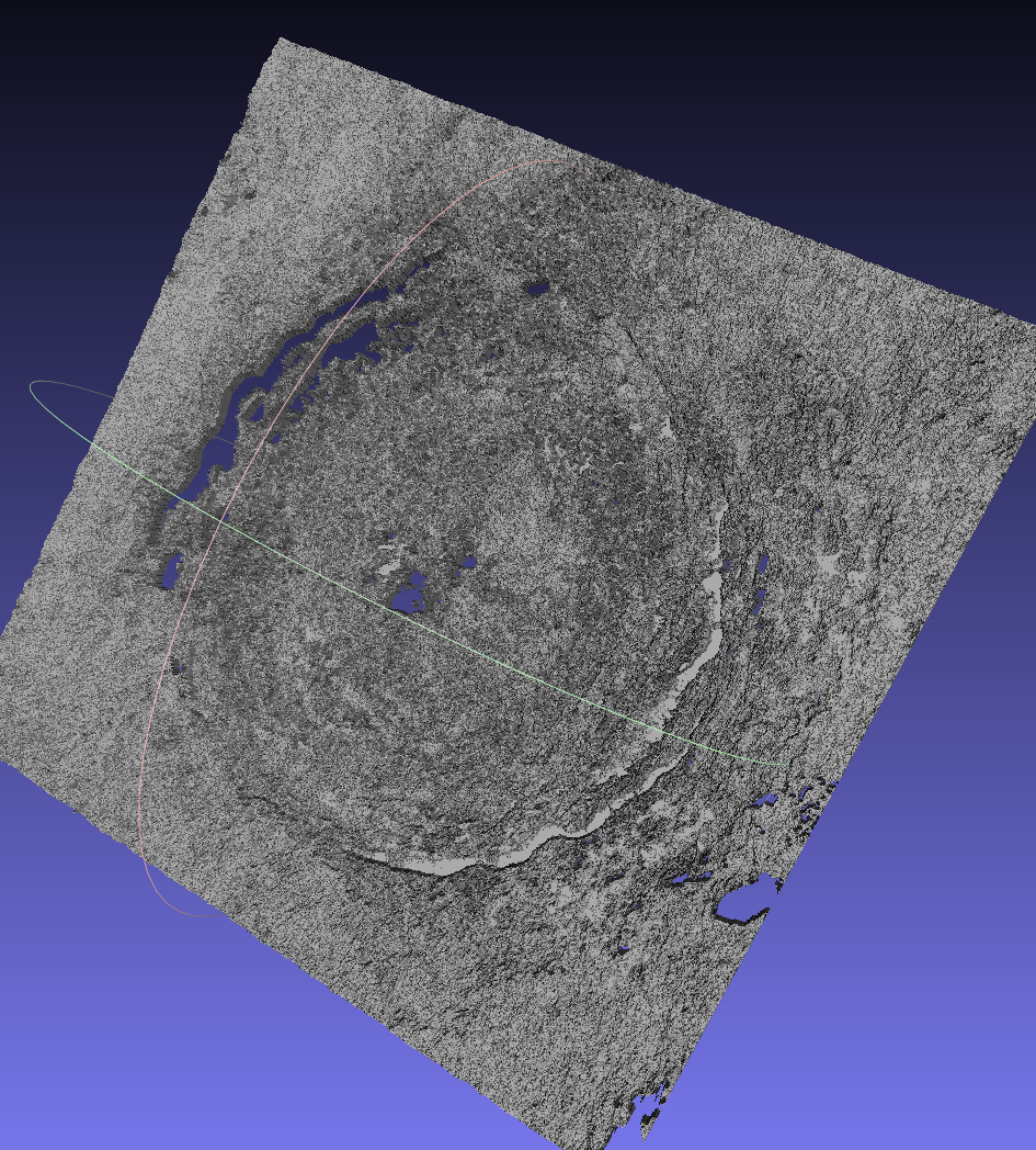

I detected that I received inverted mesh at the end. By using the inverted grascale image I got better result. (well pointed stl mesh)
Then I go to the site of NASA to get more detailed images of Copernicus and probably color map of leveling for the crater - and I found the STL! :-) Already prepared by NASA. These cool people are published some models and between them my crater! :-). All these models are available here
\Molding
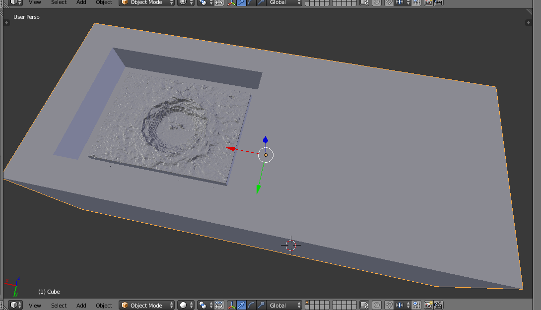
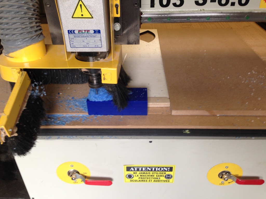
Now when I have my 3D model - I can do molding. In Blender I took the STL file and generated the brick with sizes same as Wax block and by applying boolean I inserted it inside. So now I have positive of my crater inside a brick with some standing around (1cm deep). I did not taken in account the sizes of end-mills, but it passed ok this time. Normally we need to check if end mill can pass in all holes, as well the inside part need to have rounded corner by radius of bigger endmill that will be used for rough milling.
Now we go to VCarve and we prepare path. For the rough pass it quiet simple. But for the fine path I saw that endmill tries to pass in places where it should not. And as it has con form it may have a trouble to go down to surface at the corners. So I found that we can limit the fine path by vector (we can simple draw square inside the VCarve and select it as a vector that will limit the milling area). Screenshots are below
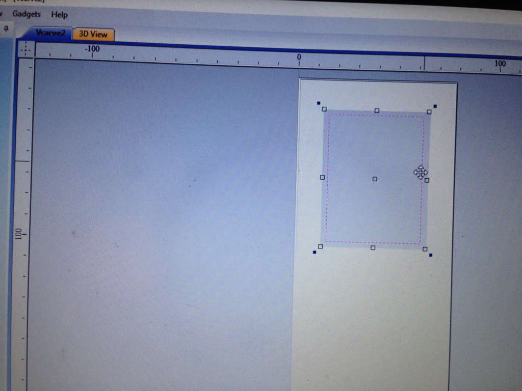 We draw the vector that will limt the zone for the carving
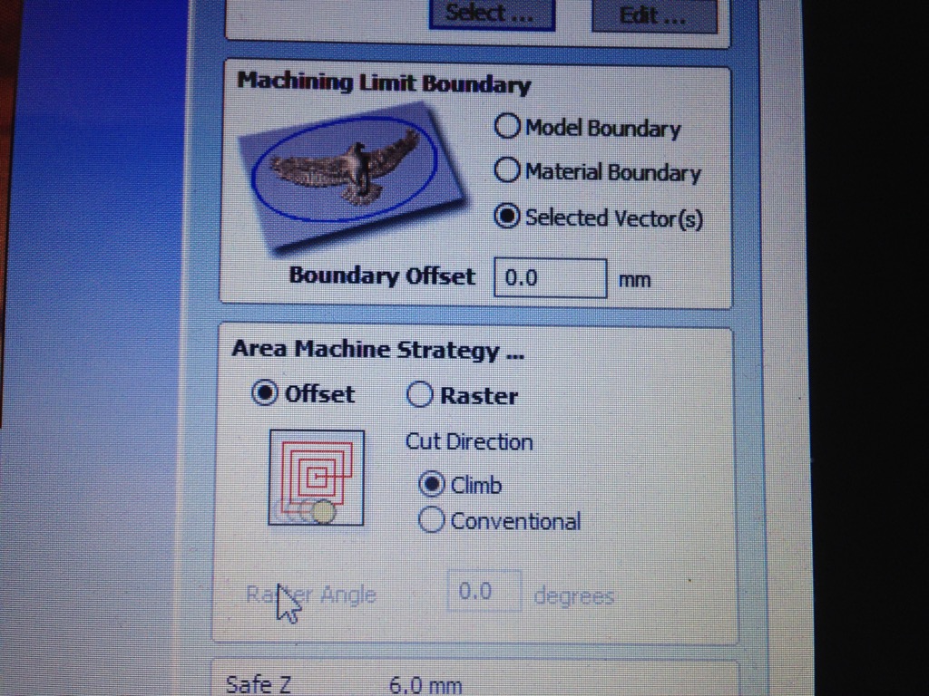 We set limit for path inside the selected vector
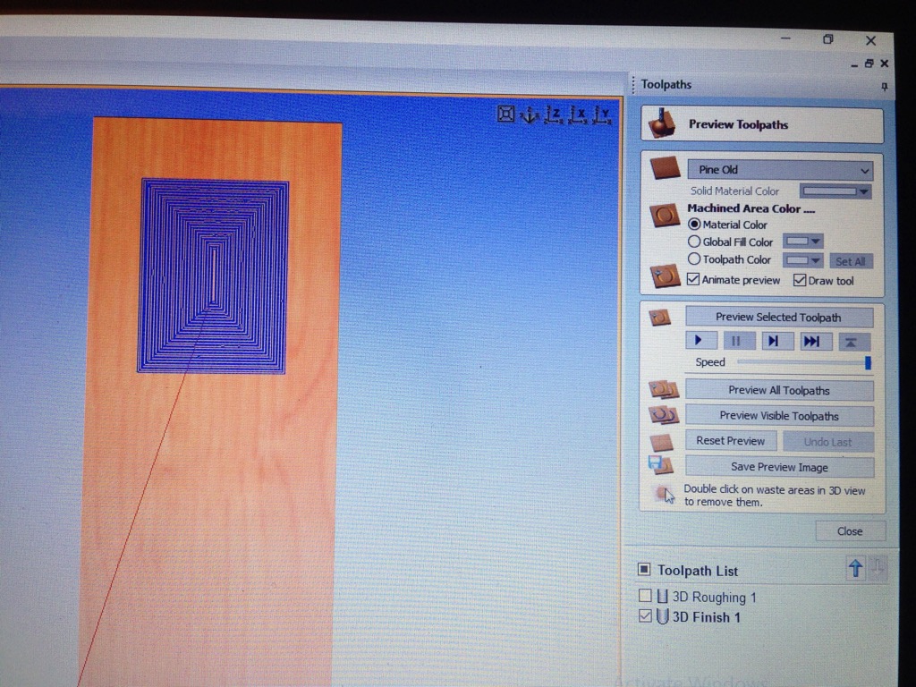 We see result
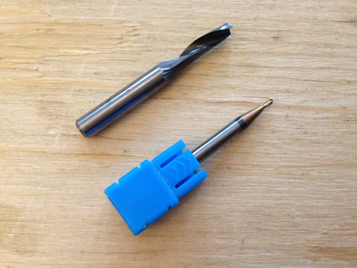
By doing this I limited problem of not very long end mill bit that can not pass to each corner correctly. Now let do machining. We have 1 tool changing. You can see used end mill bits
Casting
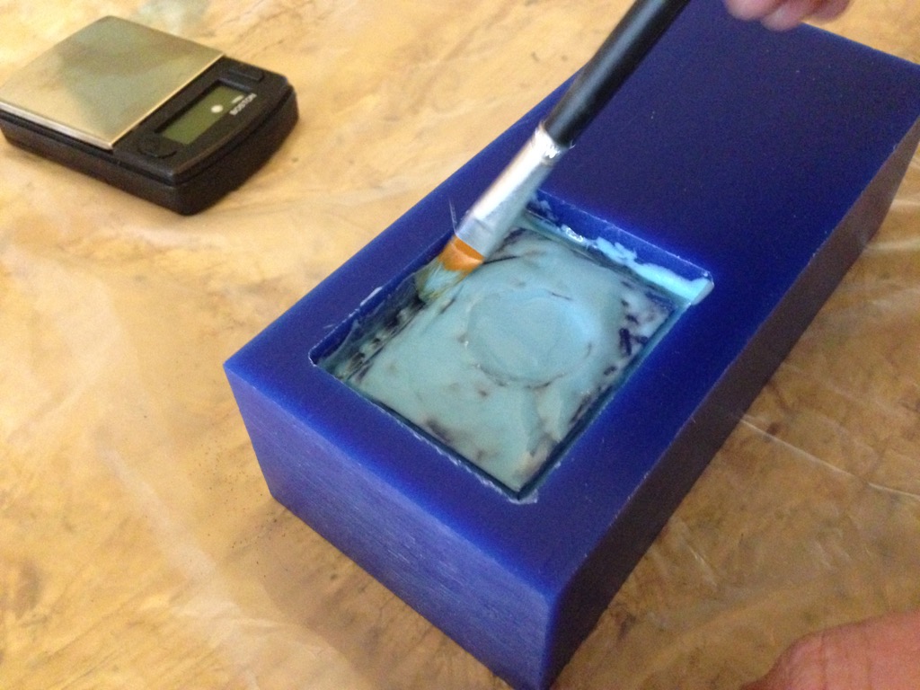
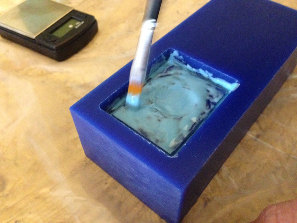
After we received the result molding we prepare the silicone with harderer in consistence 95% / 5%. We will fill the molding by the silicone to have a next step negative mold. That later we will use to have a positive models of the crater.
Important notice: When we put silicone into modling we put it using the very careful and slow flow and always in one corner that it fulfill the form by itself. It must be done for avoid the bubbles.


Then 24 hours of waiting. It need to become dry.

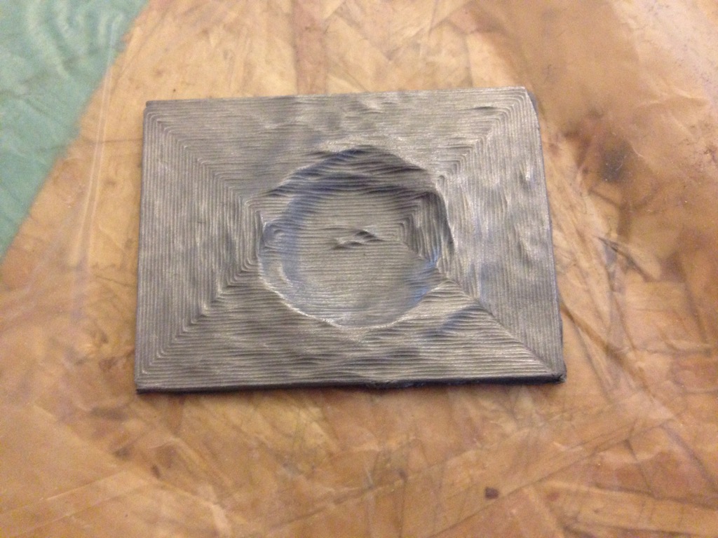
Let see what we have. And let use a hard resine to make a model of crater.

Now we put bi-component resine that become hard very fast. We add some aluminium powder in it to have a metal color. We can see that molding is quiet OK regarding the borders and deep. So it contain enough place to put resine in it and not too deep to have waste the materials.
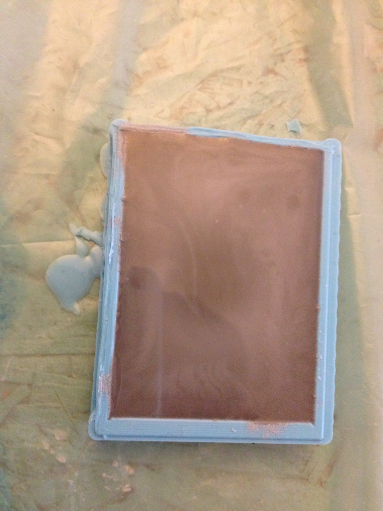
And let see final result.... Not good.. :(. Looks like that VCarve setting for final path was not OK. It is clearly visible on final model. The final path should be done in another way - X / Y path and not like a rough path.... But we still can recognize the copernicus crater :-)