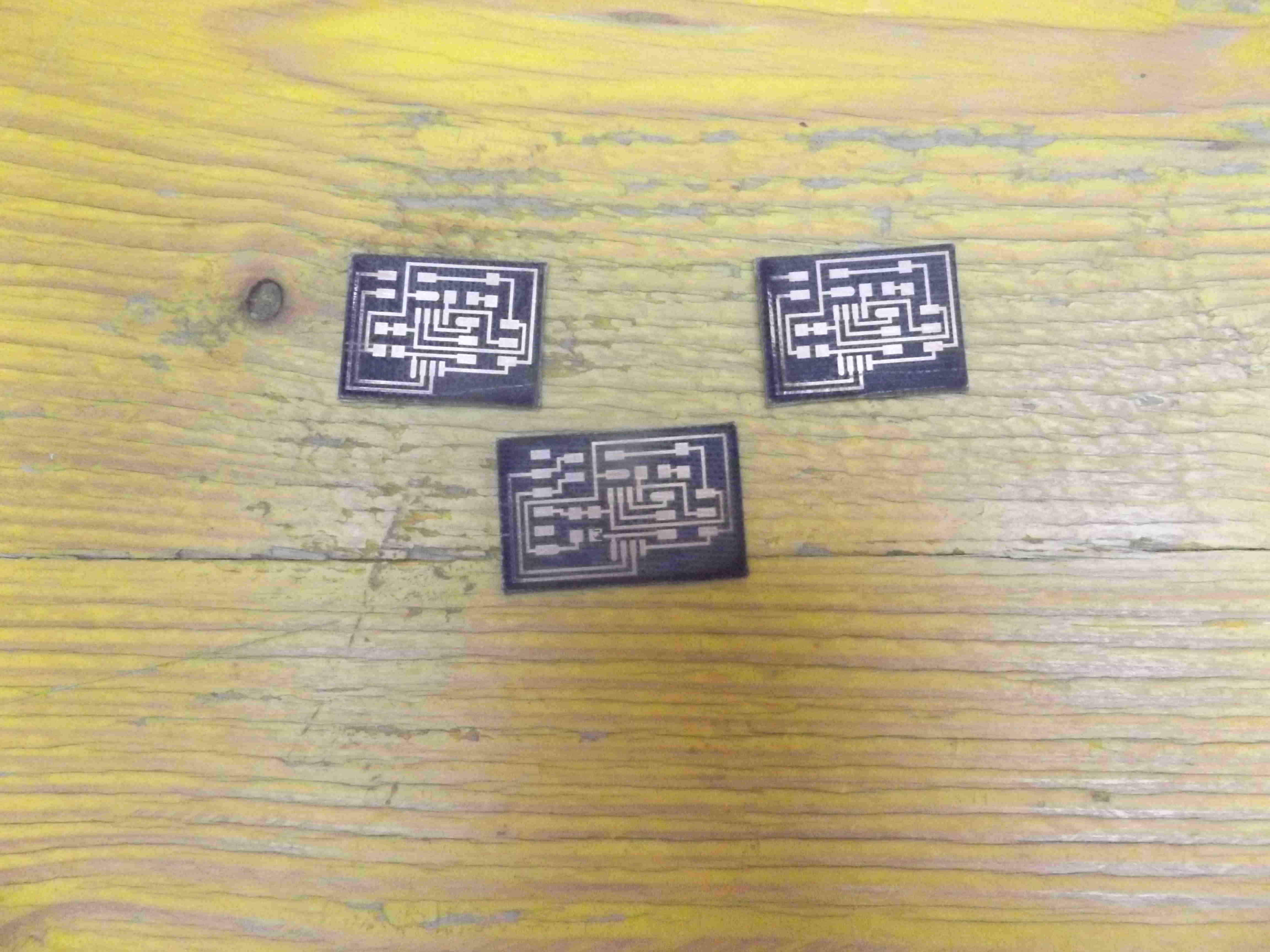
This week assignement is about networking and communication, here I impliment serial bus I download the bridge , node1 and node2 , I mill and stuff the three boards and upload the program adapt code in node1 and node2, frequency F_CPU = 8000000 and node_id equal 0 for bridge board, 1 for node1, and 2 for node2, I use atmel studio to build the firware solution for each board.
after milling and before stuffing the boards I cut some copper layers that are not well cutted by the Laser machine with cutter gravure tool.
cutter gravure tool
bridge compilation
bridge solution
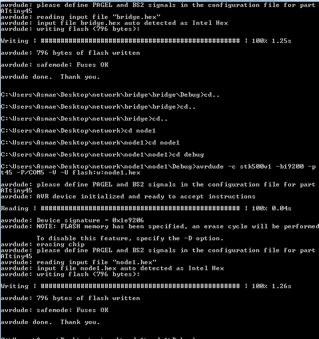
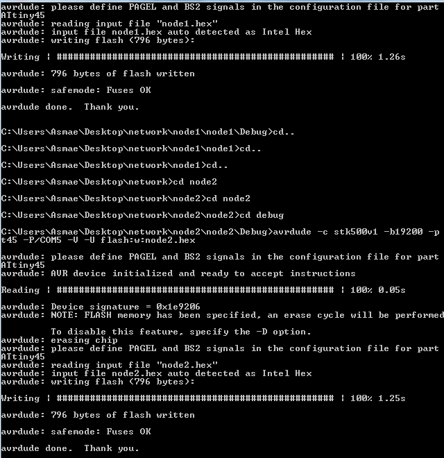
I prepare firmware folder for bridge, node1 and node2. to program with arduino as ISP, I connect the board bridge board with FTDI to usb computer port, connect arduino as isp to bridge board, from firmware bridge folder I descend to subdirectory in which I have bridge.hex file then I execute the command: avrdude -c stk500v1 -b19200 -p t45 -P /COM5 -V -U flash:bridge.hex, then to program node1 and node2 I connect node1 board to the bridge board that will provide VCC and GND to node board, I connect the programmer to node1 to program the board I enter to node1 firware descend to subdirectory that contain node1.hex file, and execute the command: avrdude -c stk500v1 -b19200 -p t45in -P /COM5 -V -U flash:node1.hex, and repeat for node2 to program. here the shortscreens.
serial bus.
testing
I use tera term terminal emulator to send input values to the boards programs.
serial bus test values sent shown on screen.
this should flash all nodes and flash twice the node sent to serial monitor. results on video.
debug
these are the problems encountered during implemention of serial communication bus.
to compile the code I needed to define F_CPU 8000000UL in it, during testing node1 was not appearing in the tera terminal and not responding, because TX,RX were not soldered well. couldnt upload the code on node2, I check with multimeter all connections solder where needed and upload the code again. to show the text on the left on terminal I configure setup-->terminal-->newline/receive--LF.
boards files are this and this . for bridge and two nodes. To download files for fiber laser and firmwares.
here is the bridge file for fiber laser. here is the node1 and node2 file for fiber laser. here is the bridge.hex file. here is the Makefile. here is the Makefile. here is the node1.hex file. here is the Makefile. here is the node1.hex file. here is the Makefile.
 cutter gravure tool
 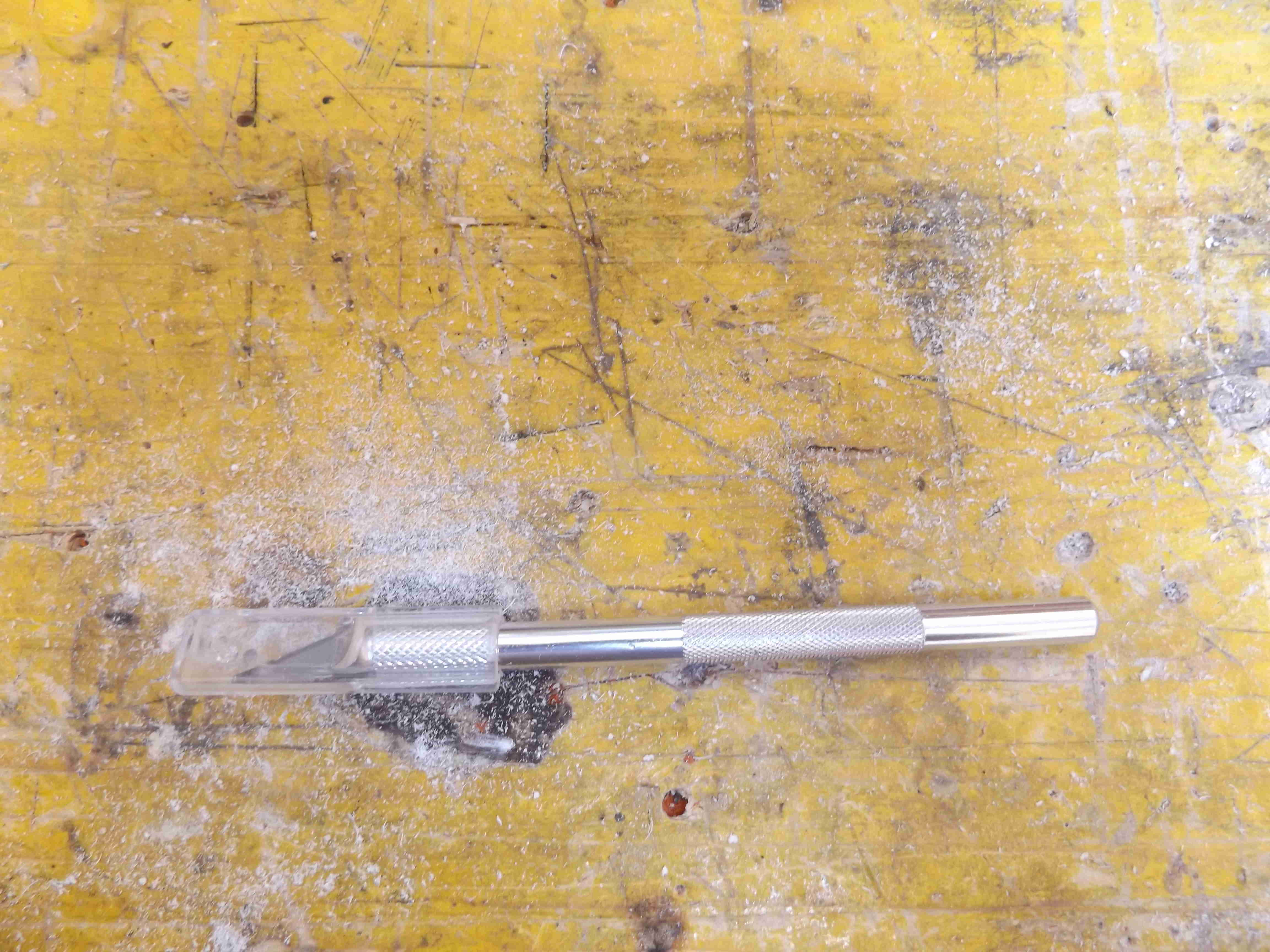 bridge compilation
 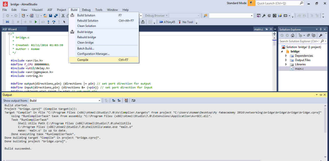 bridge solution
 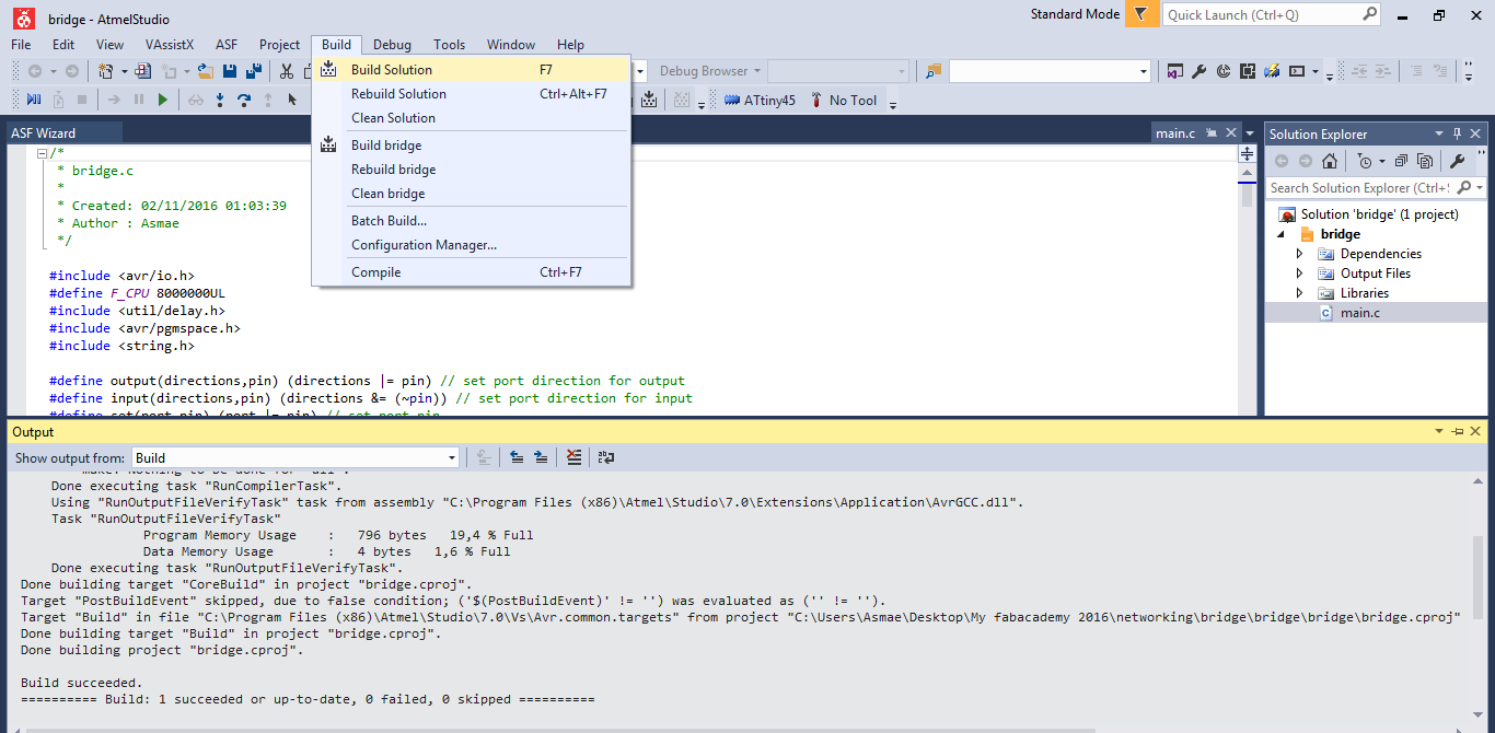 I prepare firmware folder for bridge, node1 and node2. to program with arduino as ISP, I connect the board bridge board with FTDI to usb computer port, connect arduino as isp to bridge board, from firmware bridge folder I descend to subdirectory in which I have bridge.hex file then I execute the command: avrdude -c stk500v1 -b19200 -p t45 -P /COM5 -V -U flash:bridge.hex, then to program node1 and node2 I connect node1 board to the bridge board that will provide VCC and GND to node board, I connect the programmer to node1 to program the board I enter to node1 firware descend to subdirectory that contain node1.hex file, and execute the command: avrdude -c stk500v1 -b19200 -p t45in -P /COM5 -V -U flash:node1.hex, and repeat for node2 to program. here the shortscreens.
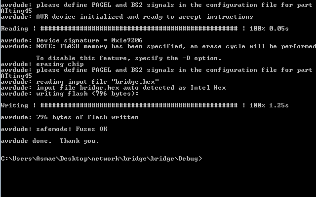
 serial bus.
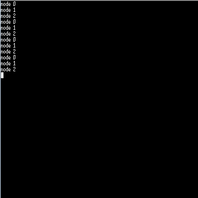 this should flash all nodes and flash twice the node sent to serial monitor. results on video.