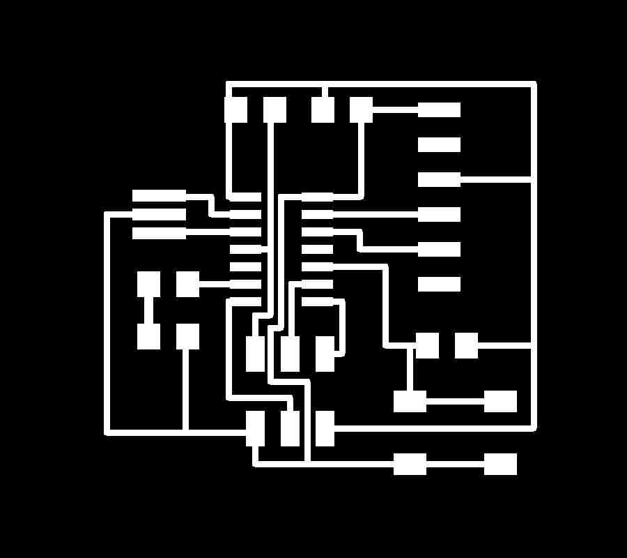
refering to attiny 44 datasheet the chip has VCC GND PA0-PA7 and PB0-PB3 physical pins Input/Output with different capabilities like interrupt, external clock, ADC etc, and reset, MISO, MOSI, SCK, signals, in the example of Electronic design the attiny 44 is connected to a button switch in PA3 and to Led in PA3 see below hechip pinout and the programs.
Fuses setting.
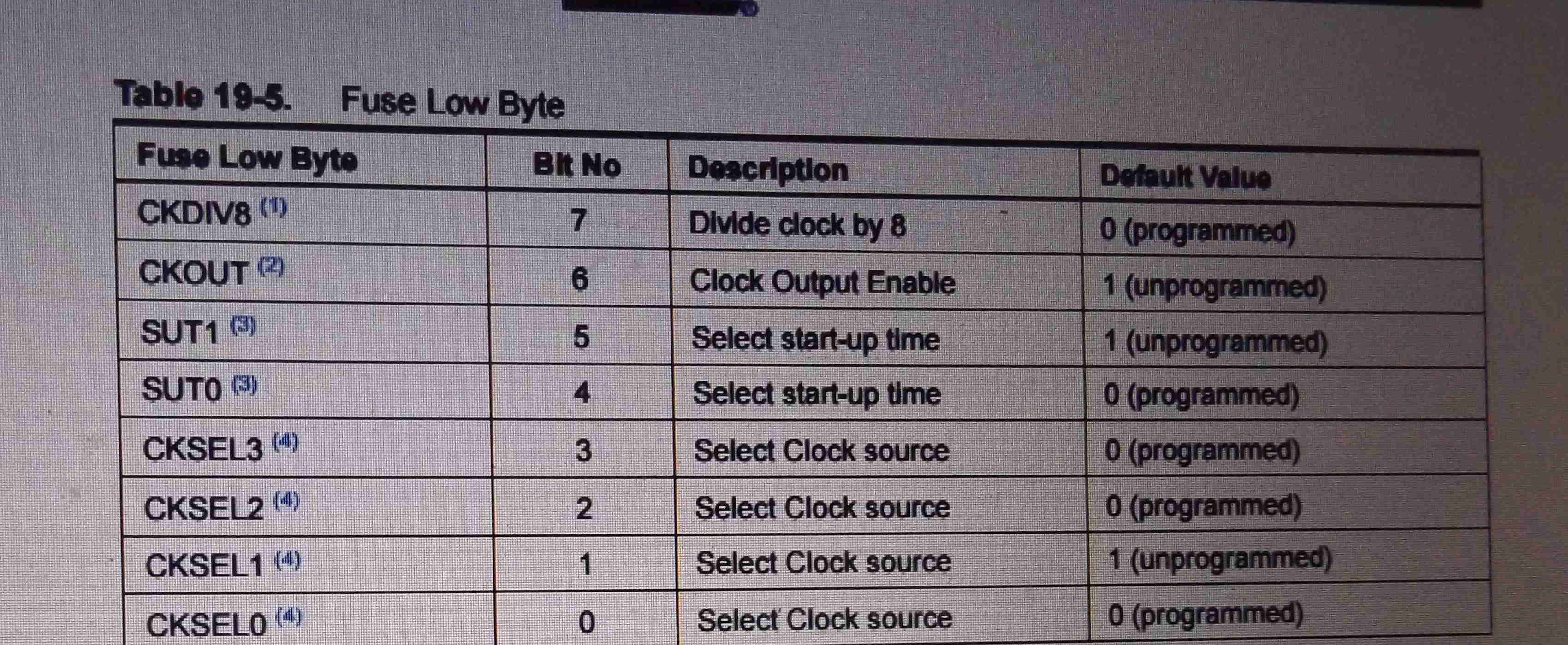
to use external clock of 16MHZ frequecy I need to set fuses accordingly before programming the board. in this and this pages details of fuses types, defaut values, fuses calculator and avrdude command to send to the Microcontroller for fuses settings.
there are three bytes of permanent storage in the chip that are low byte fuse, high byte fuse, and extended fuse, they are 1 if not programmed and 0 if programmed, theses values refer to specified bits in the chip. here are the bits that I programmed and default values and meanings.
programming low fuse
CKDIV: 0 by default means clock divided by 8 But here I will set to 1(no division factor is required)
CKOUT: 1 by default if programmed it allow chip clock to drive other circuit here I will keep it 1 unprogrammed
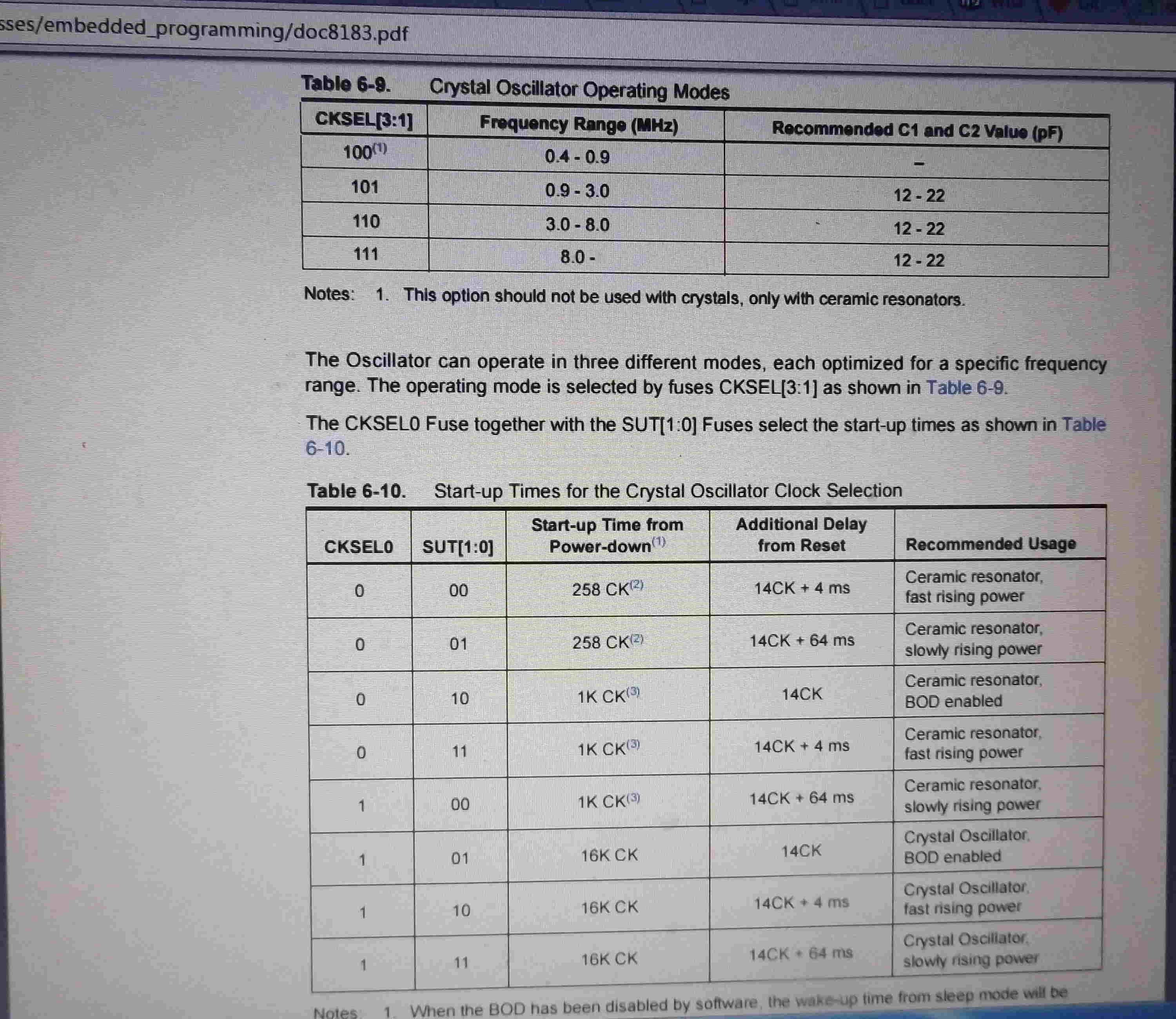
SUT: 10 by default start up time for external clock the longest to ensure that MCU is kept in reset mode when the clock is not stable value kept the same 10
CLKSEL: 0010 by default if its internal 8MHZ oscillator but here Im using external 16MHZ ceramic resonator programmed 1110
programming high fuse
RSTDISBL 1
DWEN 1
SPIEN 0 programmed to eable serial program and data downloading 159
WDTON 1
EESAVE 1
BODLEVEL 111
extended fuse programming
SELDPROGEN 1
here low byte fuse is 01101110 in binary which is DE in hexadecimal, high byte fuse is 11011111 (DF), extended fuse is 11111111(FF).
the command to program fuses using ardino uno as ISP is:
avrdude -c stk500v1 -P/COM5 -b19200 -p t44 -V -U lfuse:w:0xDE:m -U hfuse:w:0xDF:m -U efuse:w:0xFF:m
command to program fuses using fabisp programmer is:
avrdude -c usbtiny -P/COM5 -b19200 -p t44 -V -U lfuse:w:0xDE:m -U hfuse:w:0xDF:m -U efuse:w:0xFF:m
its also possible to set fuses using software, further explaination in this page. to run at full 16MHZ I need to divide the clock by 1 instead of 8 the default value: adding this lines to main code will set the lfuse at the desired frequency.
CLKPR = (1 << CLKPCE);
CLKPR = (0 << CLKPS3) | (0 << CLKPS2) | (0 << CLKPS1) | (0 << CLKPS0);
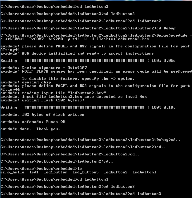
then to program the Microcontroller I prepare the firware in c and Assembly putting results hex files and makefile in the same folder then I enter to the folder where the hexfile is found and send it to the AVR using this command. here one command for programming with arduino as isp and fabisp respectively. repeat from firmware where hex file is located, replace hex file.
avrdude -c stk500v1 -P/COM5 -b19200 -p t44 -V -U flash:w:led1button.hex
avrdude -c usbtiny -P/COM5 -b19200 -p t44 -V -U flash:w:led1button.hex
Embedded programming.
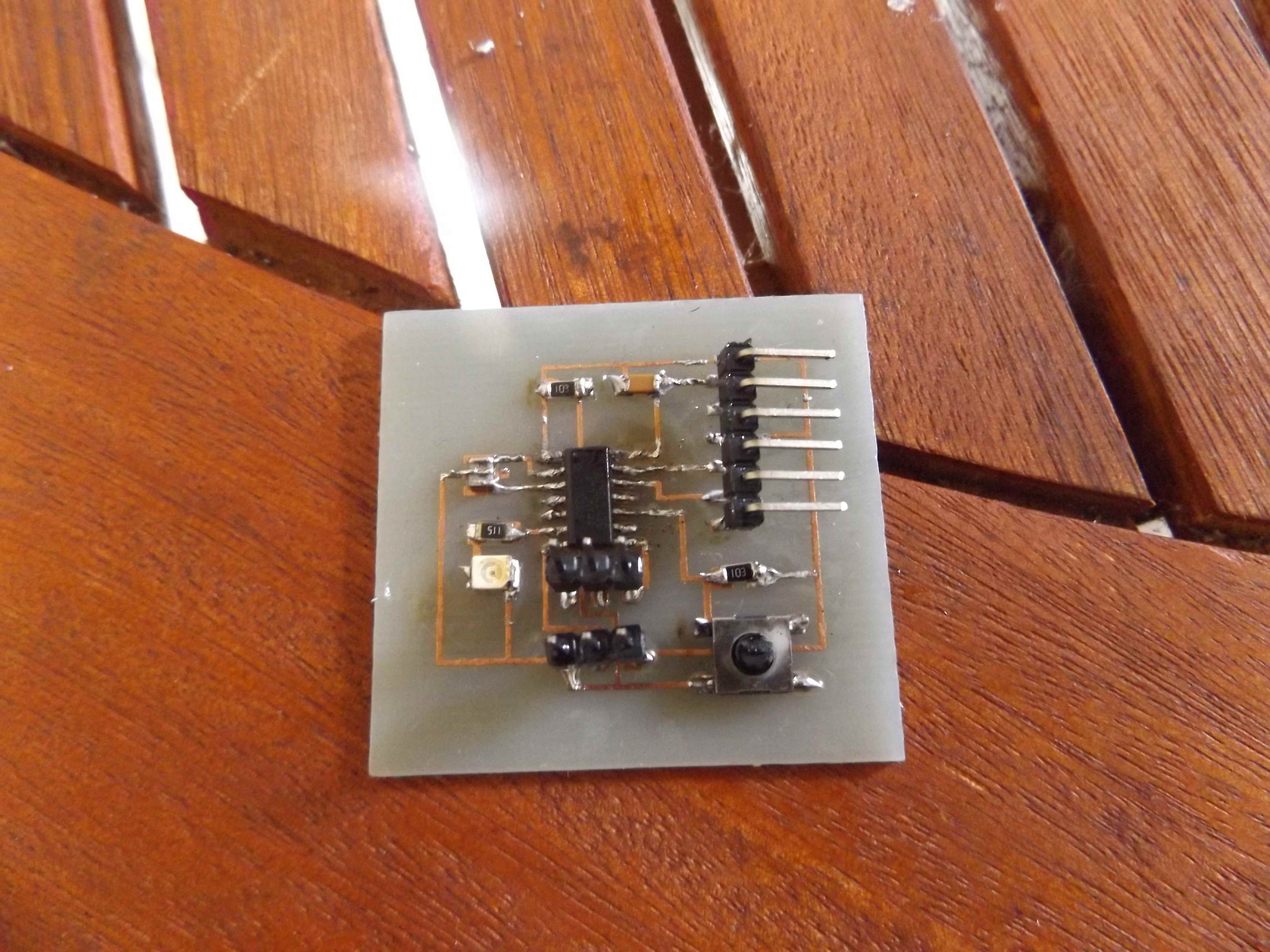
this week project is to program the hello_world board realized in electronics design week. in the beginning I could not upload programs to this board!, after testing with multimeter, desoldering and soldering (attiny 44), my first board was destroyed and I prepare an other one to mill and stuff considering thicker copper lines in my design. in fact this didnt solve the problem, I was using two 3X1 pin connecters instead of one 3X2 pin conncetor because the 3X1 that I found in the local online electronics and in my designs I supposed to use 3X2 so they were not totally conform, problem were solved when I replace this component according to my design. I couldnt realize this board in fablab casablanca because the cnc machine was not available on time. so the card I programmed in this exercice is made in casablanca but not in the lab by a chemical way, I stuff the board checking connections, below are the screenshots of the schematic, board.
Electronics board, and outline.
C programs.
to create a c project in atmel studio. I open a new project, in C/C++ categorie, click on GCC excutable project, add project name and browse project location, project solution is set automatically, then I choose device family its ATiny, ATiny 44, build->compile to compile the code, corret any syntax error in the code if necessary, this will also make the makefile, then build->solution this will make the hex file that will be uploaded to the microcontroller during programming session, here are c projects.
in this program (8 bit)direction register DDRA is set to 0/1 value in one of theses pins (PA7, ,PA1,PA0) if 1 it is an output pin on portA if 0 its an input pin on portA here is an output pin7 on portA. PortA is an 8-bit register that stores logic to output on the according physical pin, here output pin7 is set to 1 on portA. will make led on. in this port
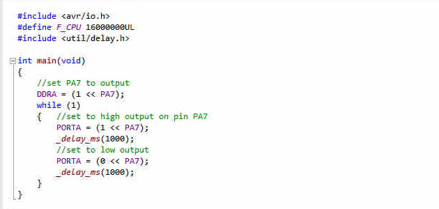
in this program DDRA pin7 is set to output pin, and PORT value of this pin is 1 for 1 second and 0 for 1 second. so led on portA pin7 is blinking.
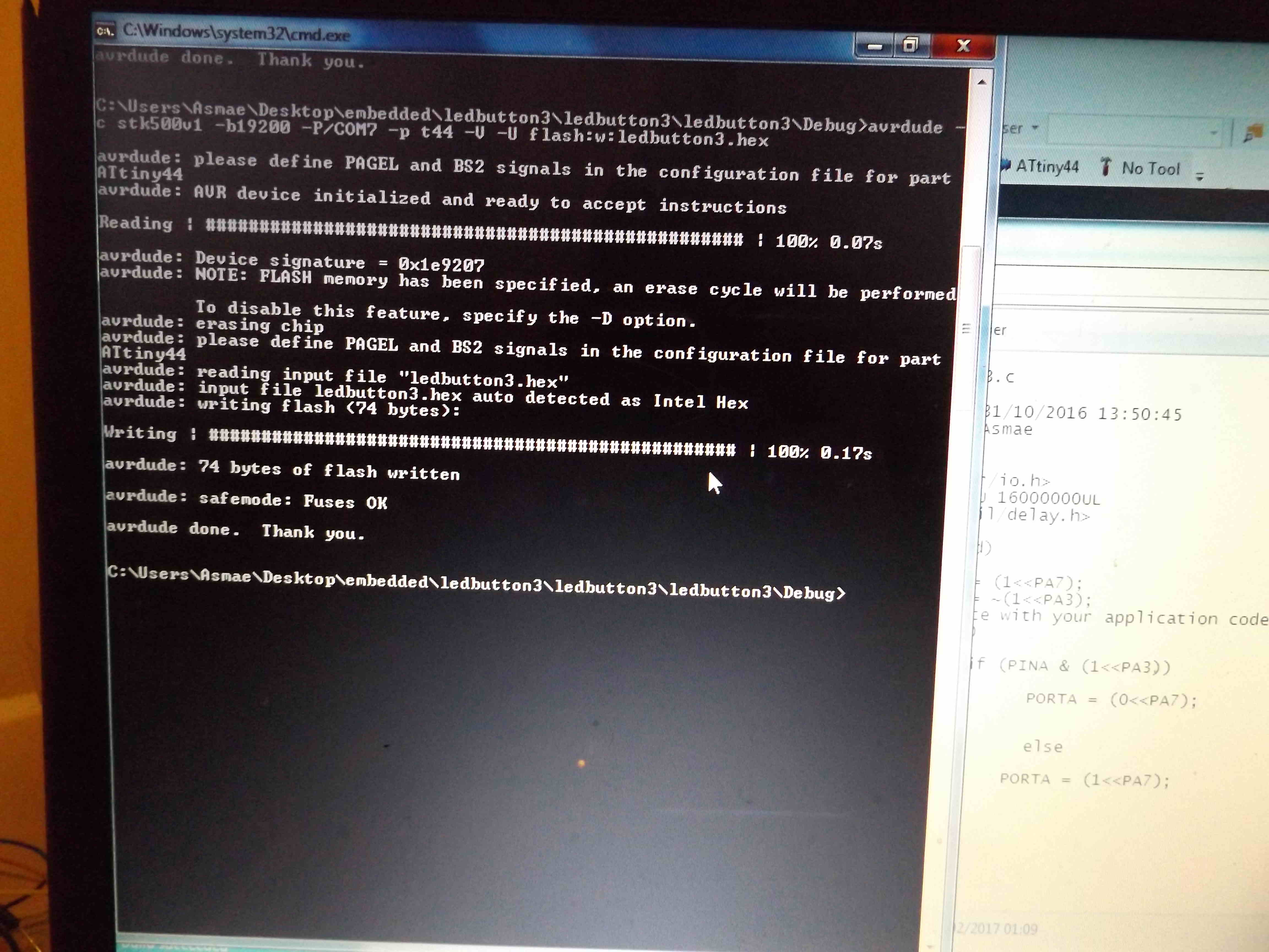
in the third program, there is pin PA3 is set to input and PA7 is set to output in DDRA register, PINA is an input register, values to read are stored in the according pin(PA7....PA0), in the circuit shematic PIN3 is connected to pullup resistor and switch button, if no switch is pressed this value is different from 0, if the switch is pressed this value is 0, in the code led is on when button is pressed and 0 otherwise, in the code if condition read pin3 and compare with either 0 and 1 when it is equal to 0 then led is on otherwise led is off.
programming board with hex code.
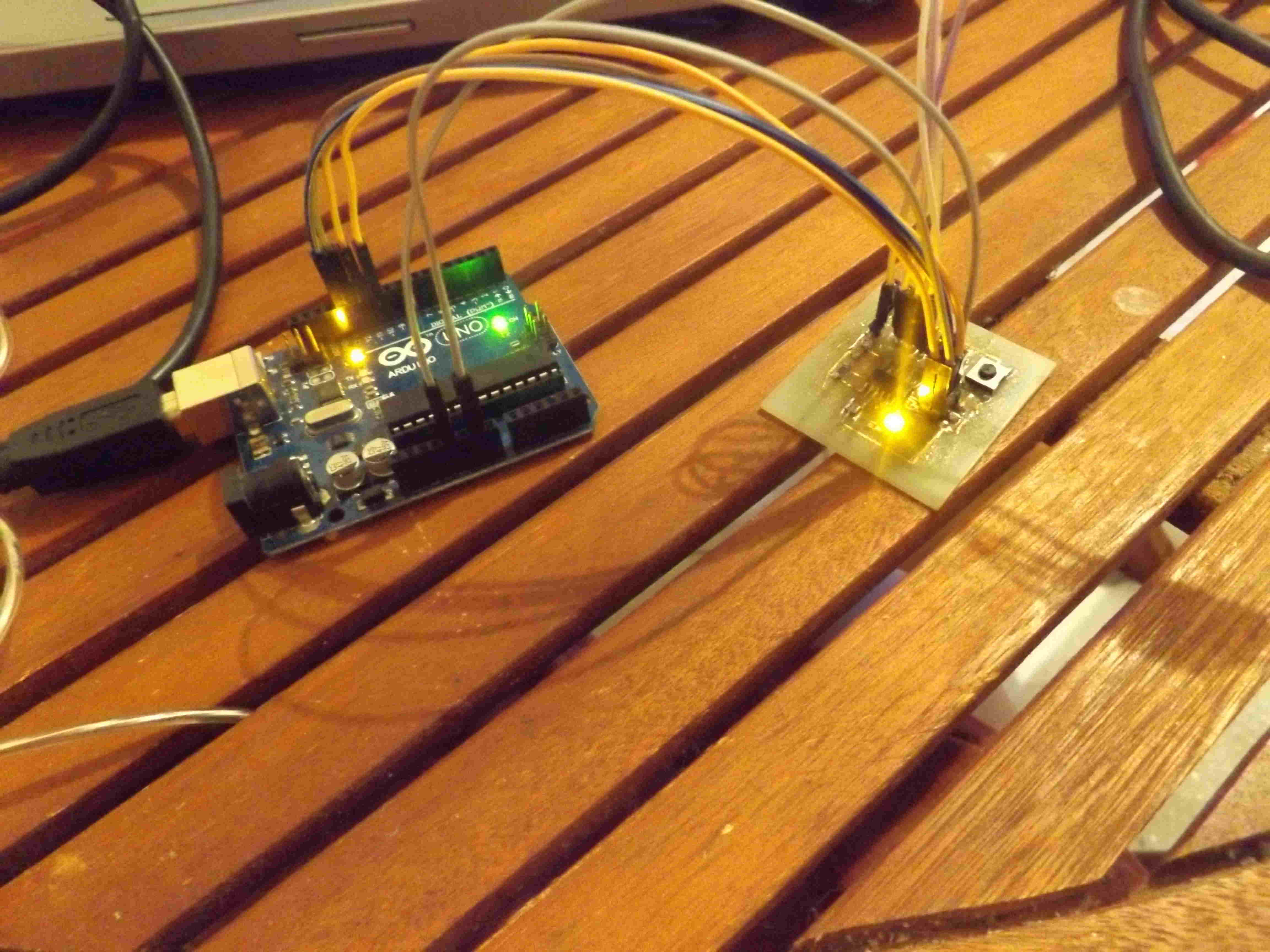
for programmin the board I need: 5V FTDI/USB cable, programmer FabISP or arduino uno as ISP, or any other programmer, firmware, jumpers here programming board with ledbutton2.hex, and ledbutton3.hex
Arduino IDE blinking led.
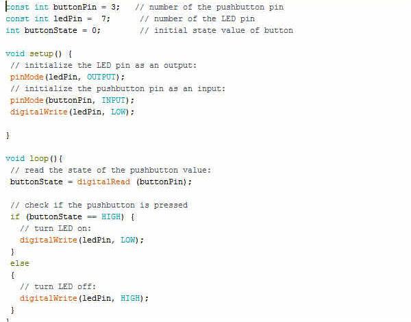
to program with arduino IDE I need to install the bootloader that will set the fuses and upload the program using corresponding programmer steps are:
tools--> card type(Atiny44/16MHZ)--> port-->COM5 programmer-->arduino as ISP/ usbtiny tools-->bootloader, then to program the avr I compile the code and I upload arduino program using progarmmer.
to add attiny 44 to arduino IDE library I folllow this tutorial.
results on videos.
to download eagle files c, assembly firmwares and arduino program. here is board file in eagle. here is board traces file for cnc. here is board outline file for cnc. here the led1button.hex file. here the Makefile for led1button here the ledbutton2.hex here the Makefile here the ledbutton3.hex here the Makefile here led arduino program.