this olive harvest tool is designed as described in the first chapter using Blender
2D modelling
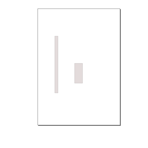
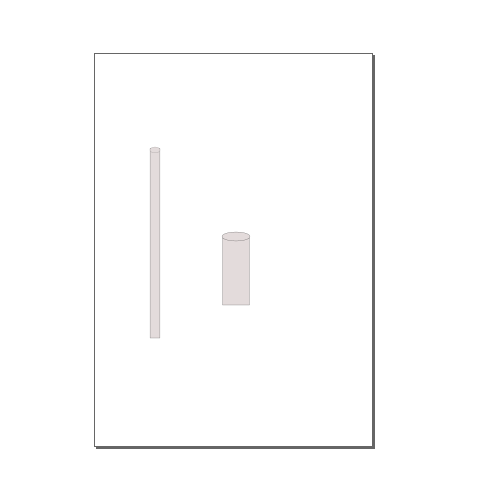
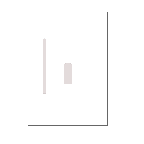
I use Inskape to sketch 2D tool, I add 2 separate rectangles adjust the two sizes one big and one small, then I add 2 small ellipses put each ellipse in one retangle side, make sure that ellipse diameter and corresponding rectangle width are identical, align vertically each two shapes click path then Union, repeat for the two other shapes to form two cylinders for hand and body, apply gray color, then linear radient to give the effect of 3D, size, align vertically the two cylinders, click path then union.
I use Inskape to sketch 2D tool, I add 2 separate rectangles adjust the two sizes one big and one small, then I add 2 small ellipses put each ellipse in one retangle side, make sure that ellipse diameter and corresponding rectangle width are identical, align vertically each two shapes click path then Union, repeat for the two other shapes to form two cylinders for hand and body, apply gray color, then linear radient to give the effect of 3D, size, align vertically the two cylinders, click path then union. here you can dowload the file on dxf format here you can dowload the file on svg format
3D modelling
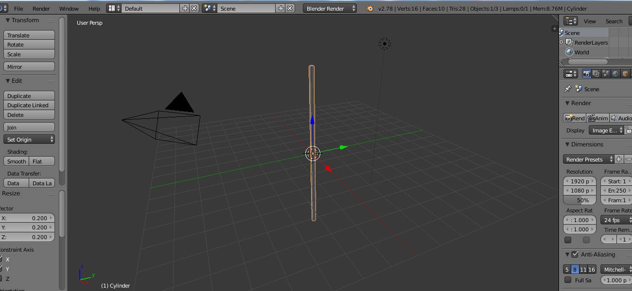
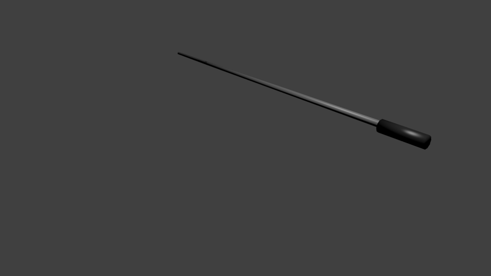
here are the step by step my tool 3D moddelling. its two cylinders body and hand of different sizes. in the 3D modelling I exepect the hand large cylinder to have an extention to make it taller, the step by step design below is respecting this rule.
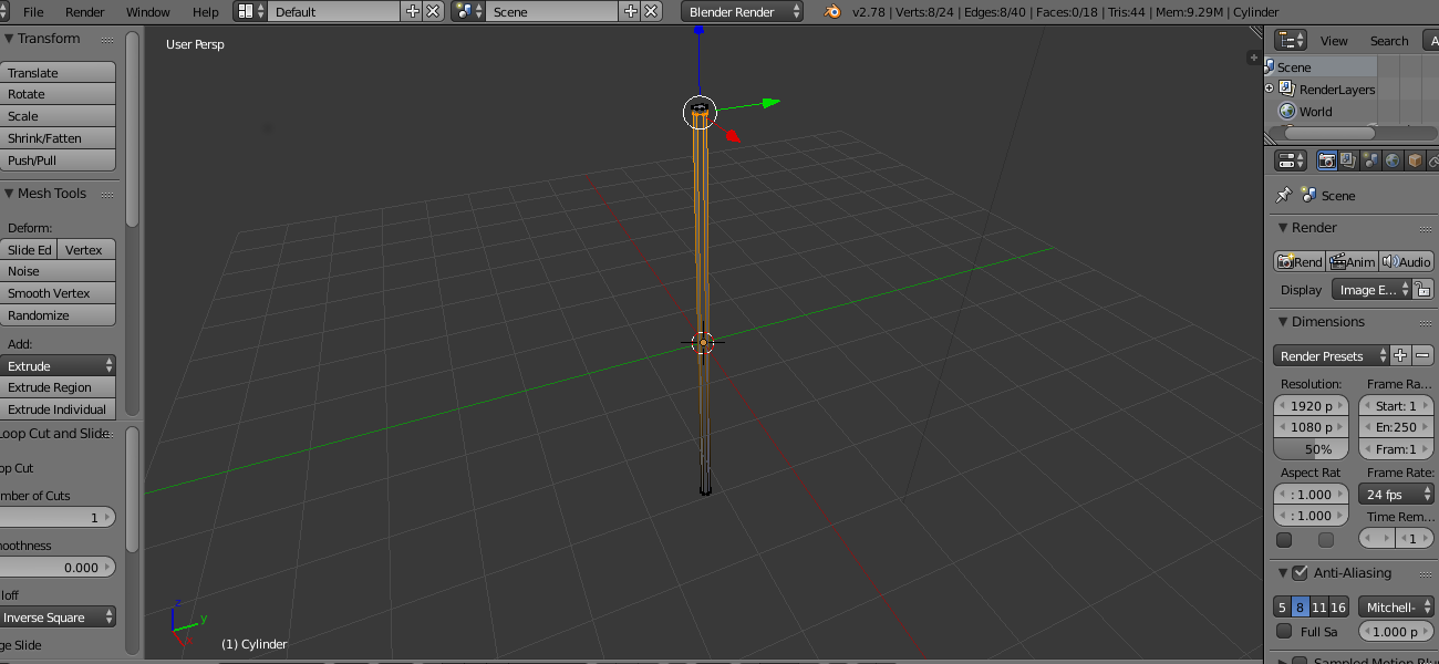
to add cylinder (body): add->mesh->cylinder in add cylinder properties I put no of vertixes to 8
to size (adjust the width): I switch to edit mode click S and shift Z to minimize over X and Y axis, I hold the ctrl key pressed to restrict the movement
to size (adjust the length): on edit mode I press S on keyboard and Z to maximize over z axis
to make the top part thinner: I press ctrl R to divide the surface, I create one near the top and minimize pressing S then shift Z and minimize, to make the top even thinner on edit mode I click on edge edit mode and I click + alt to select the outer circle press S shift Z and minimize
to create an additional part on the top in order to make the tool larger as needed: on edit mode, wireframe, edge mode select , left click+alt to select the outer loop press P to separate the selection click to cancel the movement press E Z to excrude over Z axis this part could be mounted or unmounted as preferences
to size the top on edit mode wireframe, edge mode I press , click+alt to select the outer loop then I press S shift Z and minimize
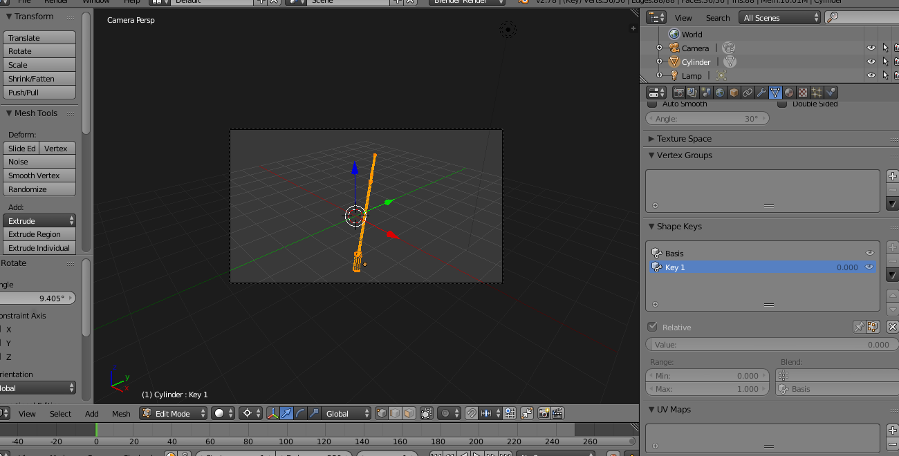
To add user interface
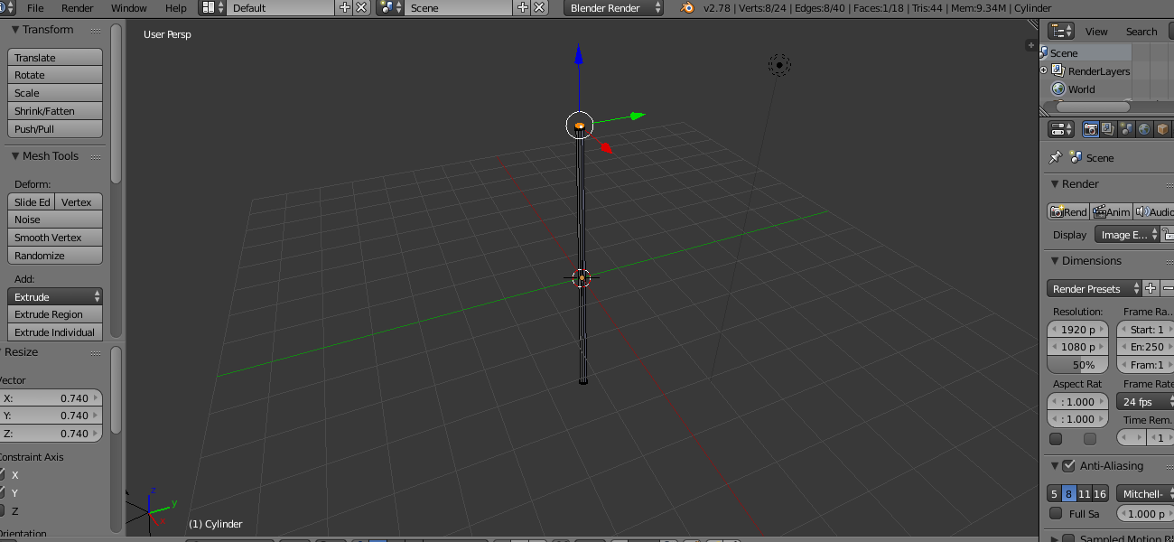
I select the object add a subdivision modifier in the outliner I click modifier-> add modifier press subdivision surface enter 2 in view and in mesh tools I click on smooth
add cylinder "hand": add->mesh->cylinder in add cylinder properties I put no of vertices to 10 and in edit mode size over x y and Z press ctrl to restrict the movement apply smooth
apply materials for both cylinders check on render paragraph
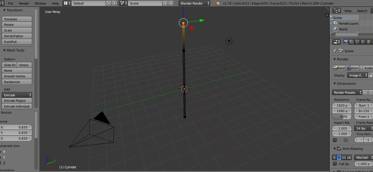
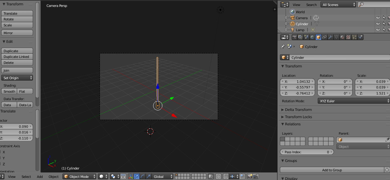
place tool's parts: on left view put body and hand adjust the left right back and front views
make it one object: select objects ctrl j
pivoting point: on edit mode press A to select all press G and move the object make the pivoting point at the bottom switch to object mode
fix the top view: on front/back press R to rotate X Y Z to rotate over a predefined axis ctrl to restrict the movement
To add user interface: on top view, edit mode, edge mode select I select the vertice edge de delete, then I select the 2 adjacent vertices edges I press F to fill the surface, on the sides I select 3 vertices edges and press F to fill the surface then I apply smouth on hand
you can download my files in stl format here and here
rendering
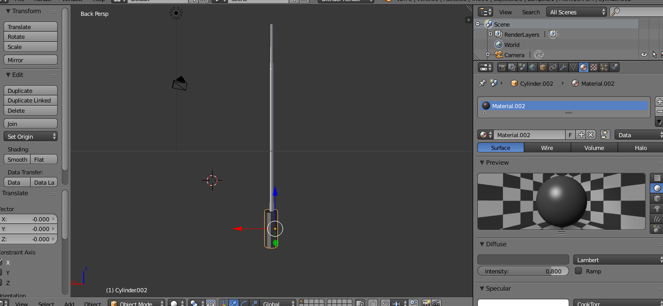
tool's body: in object mode select cylinder in outliner press material->new->diffuse->scroll bar up to select light gray keep default settings
tool's hand: in object mode select cylinder in outliner press material->new->diffuse->scroll bar down to select dark gray keep default settings
press image to generate the render change the placement of camera light object as needed and regenerate the render
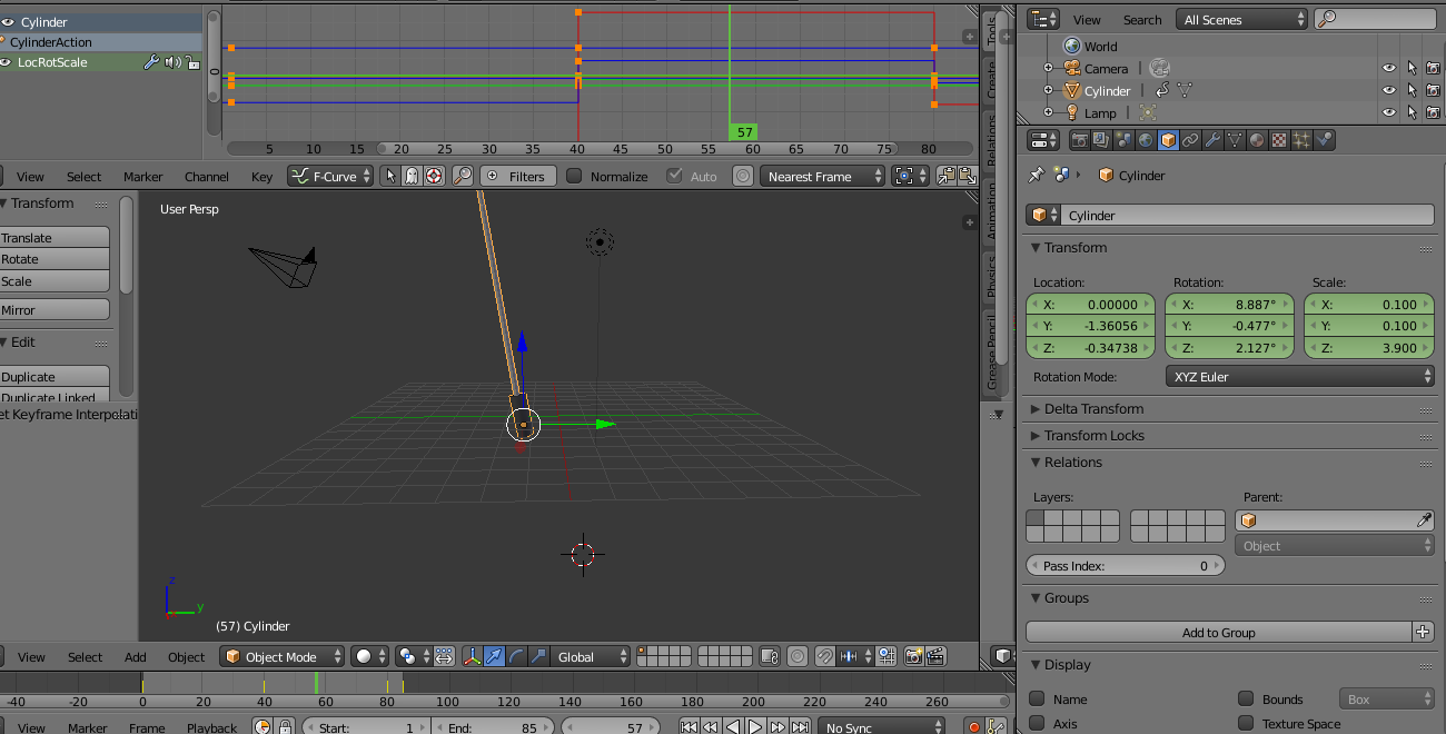
animation
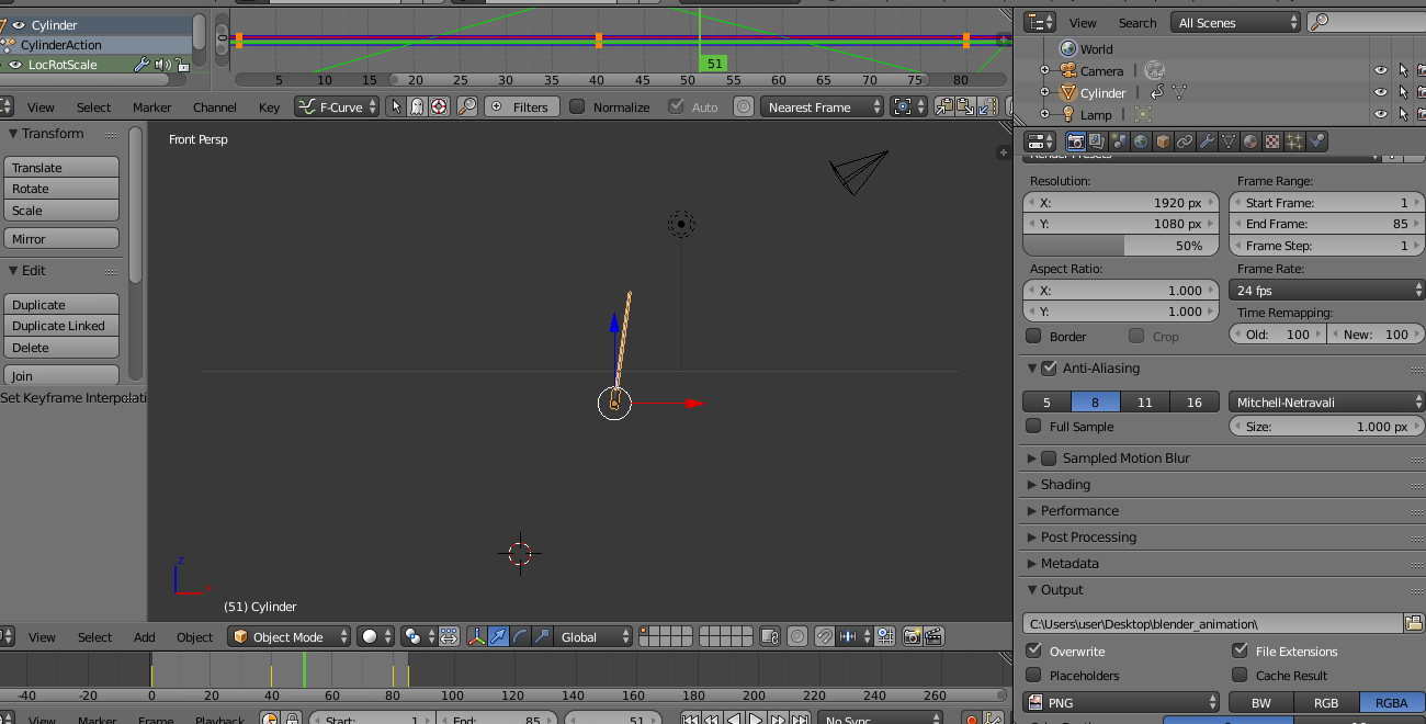
my first animation were 20 frames, in timesline frame0 I apply no rotation and insert first key in frame 20 I apply a slight rotation to the right and insert a second key then in graph editor I change key interpolation mode to linear.
to make it longer I increase the no of frames to 85 and use automatic key
in timesline I set start from frame1 to frame85 to generate 85 images for the animation, I activate the keyvalue, then I rotate slightly from left to right then I forward a certain no of frames and redo the rotation this insert a new key value, and repeat
on top I open the graph window, I press A to select all graphs, then I press key->graphs interpolation mode->linear for linear movement
switch to view camera to see the scene make sure that the tool is within the view if not move object/camera to fix the view
save the animation: see the simulation chapter
here you can dowload the file on blender format here you can dowload the animation file on blender format
simulation
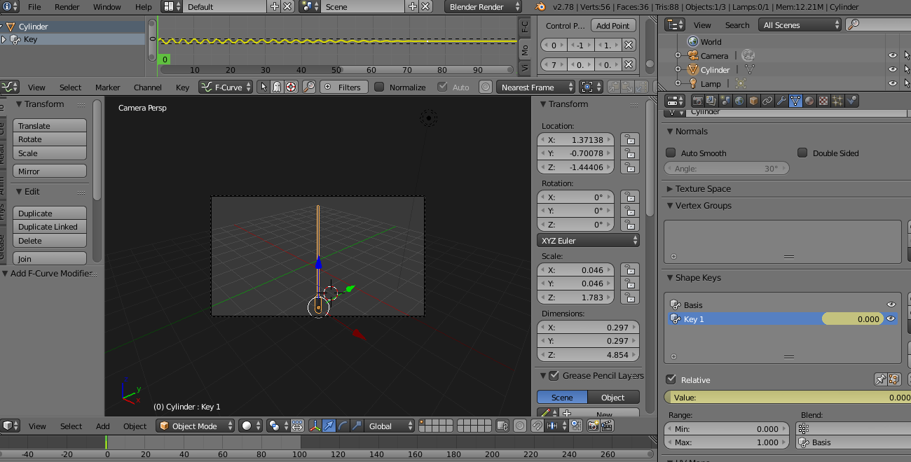
in 3D view window, top view, select the object, in outliner I click on object data, shapes key, I press +,to insert basis, the I press+ to insert a key0, I select the key, in 3D view window, I press shift c to place the 3D cursor in the center of the scene, change pivot point, then rotate over 3d, I press R rotate slightly to the right, set range min=-1 and max=1, press I on value to insert key0 value.
on top I open a graph editor window, I press N to open properties menu, add modifier, built-in function, to insert sine wave presenting oscillation, adjust frequency to 2 in order to increase speed of oscillation, amplitude =1 should be within the range in min-max to not cause a stop in movement.
to fade out at a particular time, I set the starting and ending frame of simulation, I add a modifier enveloppe add a point->frame1,min -1, max 1 then add a point ->frame75, min 0, max 0
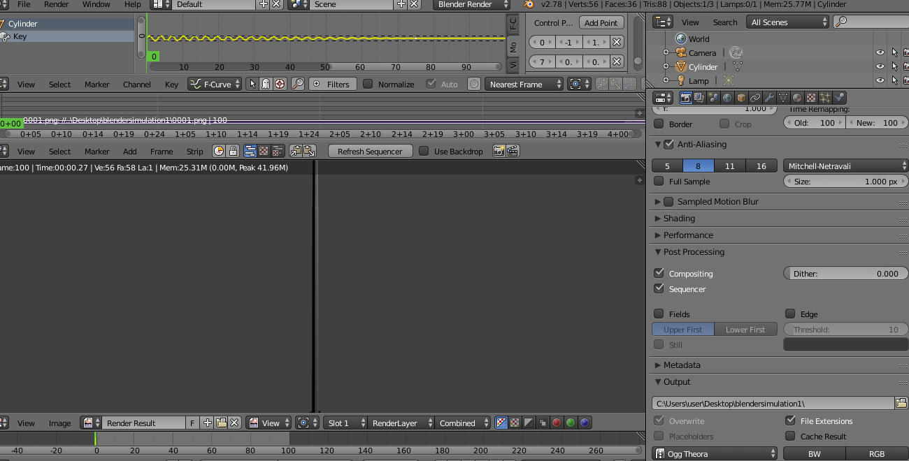
to render the images of simulation: in outliner menu->render->output->set the path of folder that will contain images->format:png->check camera view->check frame 1 in the beginning of simulation before rendering, and press ctrl+F12 to render, then check folder that contain images of the simulation.
I open video editing window->add->image->navigate to folder select all images of the simulation->add image strip, check conformity between starting frame in images imported to graph editor and timeline and adjust, in outliner, in post processing check compositing and sequencer, output format video choose ogg theora, launch render animation
here you can dowload the simulation file on blender format

 To add user interface
I select the object add a subdivision modifier in the outliner I click modifier-> add modifier press subdivision surface enter 2 in view and in mesh tools I click on smooth
To add user interface
I select the object add a subdivision modifier in the outliner I click modifier-> add modifier press subdivision surface enter 2 in view and in mesh tools I click on smooth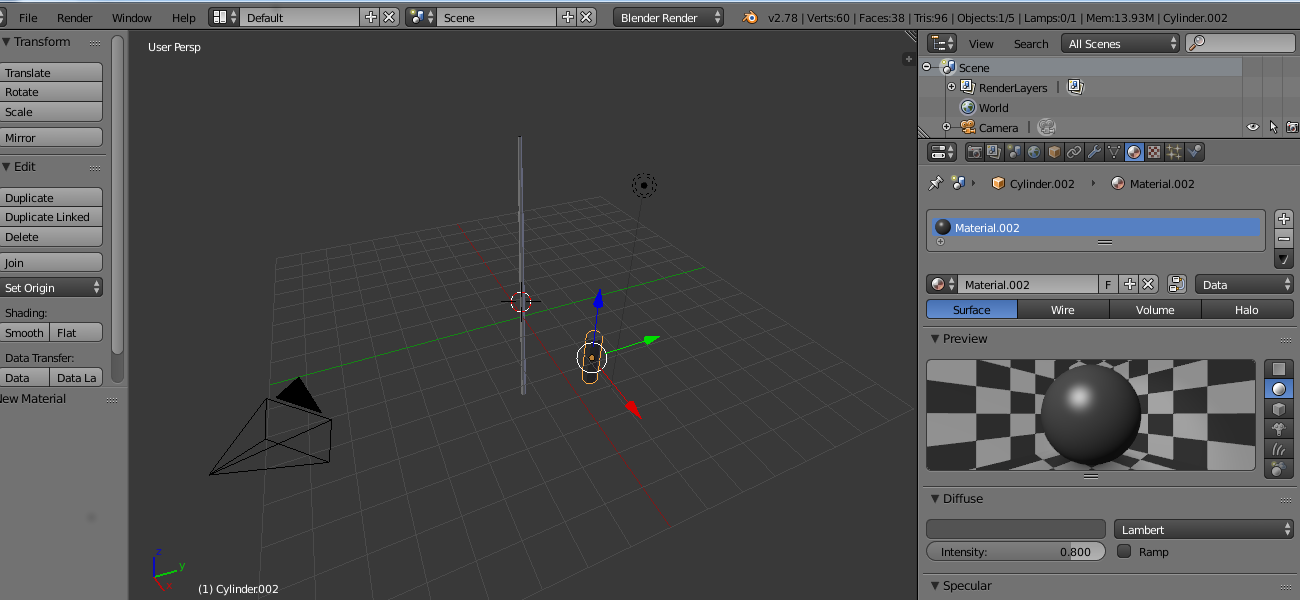