Electronics production
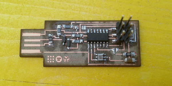
During this week we had to make practice whit PCB fabrication. starting from the [hello.ISP.44.res] trace, i used [Inkscape] to add the logos of "Opendot" and of the Fab foundation.
![[hello.ISP.44.res]](http://academy.cba.mit.edu/classes/embedded_programming/hello.ISP.44.res.png)
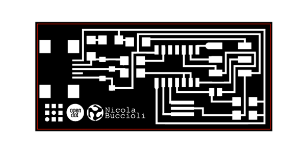
During this week we had to make practice whit PCB fabrication. starting from the [hello.ISP.44.res] trace, i used [Inkscape] to add the logos of "Opendot" and of the Fab foundation.
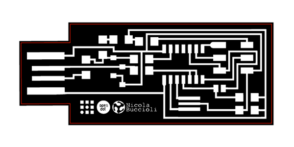
I also tried to change the usb connector of the board, to plug it directly in my laptop like an usb. Once i understand the different between USB and USBmini, i redesign the board in order to use the USB connector. The pin out of the USB and USBmini are mirrored so i had find a new path of each tracks. I used a 0 Ohm resistance to invert the D+ and D- signal track

In our lab we decide to fabricate the laser with our laser cutter [Trotec speedy 100 flexx]. Starting from Inkscape, where i've imported the .png file of the "hello.ISP.44.res" to modify the tracks and to add the logos, and i also design the borders of the PCB in pure RGB red color.
In this way the laser will engrave the black parts with the fiber laser, and after that the red line will be cutted thanks the CO2 laser. It's very important to remove the copper under the red line with fibra laser before cutting with the CO2 laser.
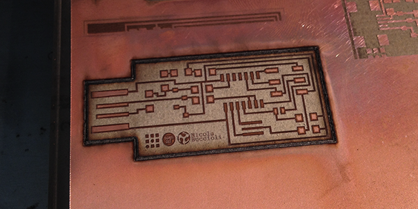
From inkscape i print the board with JobControl software to set the laser cut. The students of the previous year had found the optimal settings to make this kind of work with the [Trotec laser], so i started from that settings. Actualy the result was quite good: the copper tracks hasn't detached and the cutout of the PCB don't require more passes.
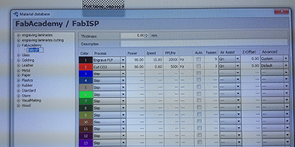
Engraving:
Type: fiber laser.
Power: 80.00.
Speed: 20.00.
PPI/Hz: 20000.
Passes: 10.
Correction: 10.
High quality: yes.
Raster correction: yes.
Cut out:
Type: CO2.
Power: 80.00.
Speed: 0.60.
PPI/Hz: 5000.
Passes: 3.
Once the PCB was lasered the practice with the solder of the components is started.
There was several tools that i never used because it was the first time for me with the surface-mount, but once i've understad the tecnique (from the inside to the outside), the work isn't been so difficult.
It's important to weld first the microcontroller!!!
Check the result..
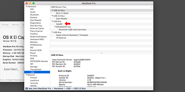
Once the FabISP was soldered, starts the programming parts.
It's been very simple thanks the [tutorial] on the FabAcademy's archive.
i work on a MacOS X 10.11.6 (El Capitan) so the first step was to download the right firmware and to install XCode from the apple store.
To program my FabISP i used another FabISP, because we got some problems with our programmer.
The next step was to compile the firmware using the following command lines through the Terminal:
"make clean"
"make hex"
Since i've got a successful message, i went foward with the command "make fuse" to set the fuses of my board with an external clock (crystal).
I've got the following message in the Terminal :
avrdude: safemode: Fuses OK
avrdude done. Thank you.
so, it was time to make the final step with the "make program" command to program my boad as ISP.
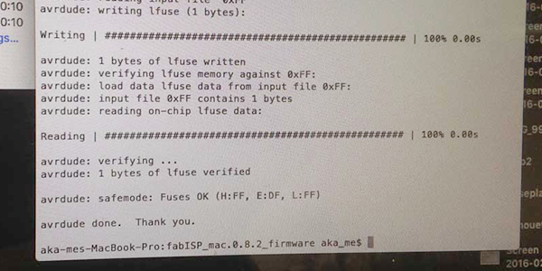
Once the programming process was done without error messages, my laptot was able to detect my FabISP in the USB devices list.