Week #3 COMPUTER-CONTROLLED CUTTING
Design and make a corrugated cardboard press-fit construction kit
Assignment
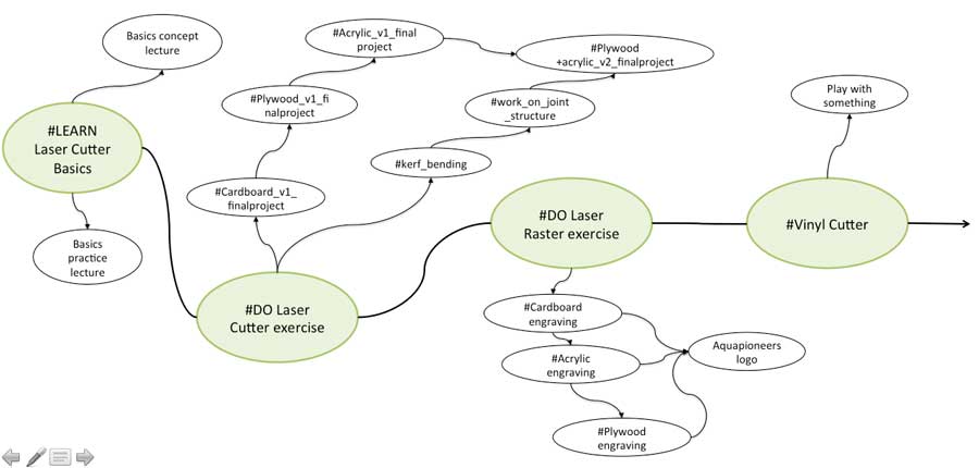
Week workflow
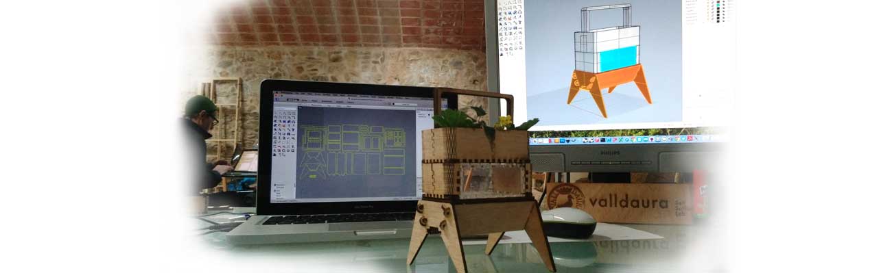
This is how I see my week
Softwares used
- Inskcape
- Rhino
- Join Control
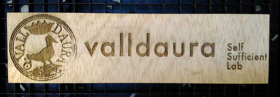
Laser engraving
At the Green Fab Lab we have a Laser cutter Trotec Speedy 400 offering a working area of 1000 x 610 mm. We started the week with the engraving technique using Inkscape and the Green Fab Lab logo. First action has been to turn on the TROTEC
STEPS with Trotec : Turn it on with the key / shift + up to adjust the level / put manually the laser on 0 / set up the right focus / close the lit
STEPS on Inkscape : Open the bitmap with Inkscape/ set document properties in "mm" and working area "1000 x 610 mm" / select black and white logo / path / trace bitmap + trace red line rectangle / save it as .svg or .pdf / print / select Trotec join control driver

STEPS on Join Control : Set material properties / select material / select material thickness / select laser power / speed / Hz / associate a color to laser function (in our case black = cut and red = raster) connect JC to engraver / drag and drop .svg file / click ready
Laser Cutting
Using Cardboard
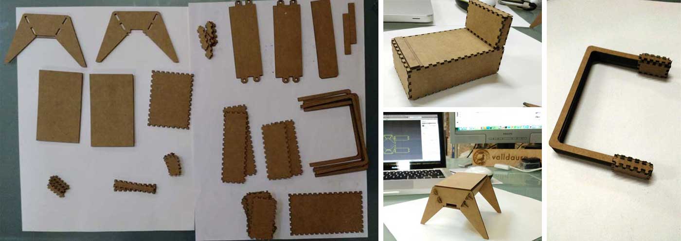
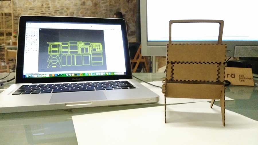
As I intend to do every week, I want to work toward my final project as much as possible. So I decided to apply the laser cutter assignments (i.e. use cardboard / acrylic / plywood / work on different joints / kerf cutting / kerf bending / etc) on the 3D model I've been working on last week with Rhino.
To start with and in order to make the "rectangular" form of the aquarium / the growbed and its two respective legs, I decided to use an open source tabbed box creator plugin for Inkscape, called Boxmaker. It can be downloaded from Github . I tried it out and what a great tip to understand "cutting kerf" concepts.
STEPS FOLLOWED WITH BOX MAKER: Select Extension / Laser tools / Tabbed Box Maker / and introduce the dimension and kerf value. Knowing that the typical Kerf Width for Laser is 0.25mm and laser diameter is also 0.25 mm the kerf value to introduce on tabbed box maker should be 0.5mm

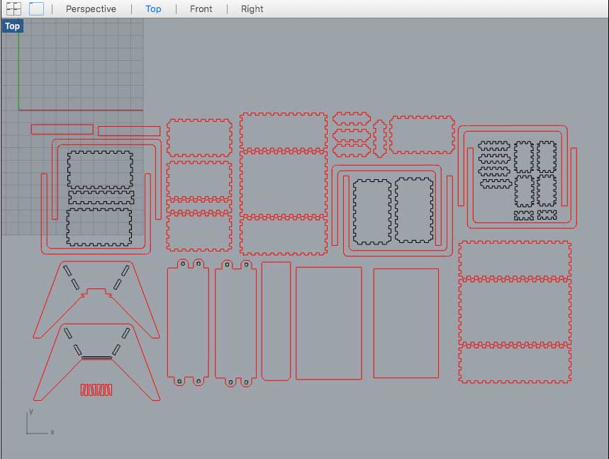
For the other 3D model modules, I've used the "Make2D" command to project their respective geometry to the construction plane to make a 2-D drawing. The Make2D command creates curves from the selected NURBS objects as silhouettes relative to the default construction planes. The silhouette curves are projected flat and then placed on the world xy plane
STEPS TO FOLLOW: Go to construction plane / select object / MAKE2D command / OK.
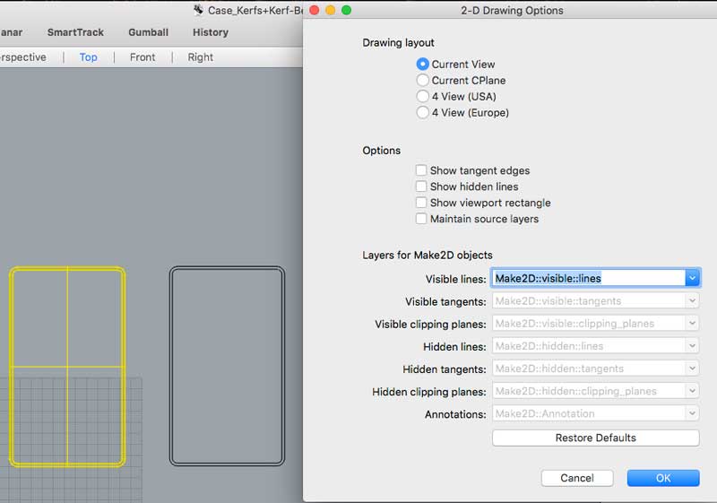
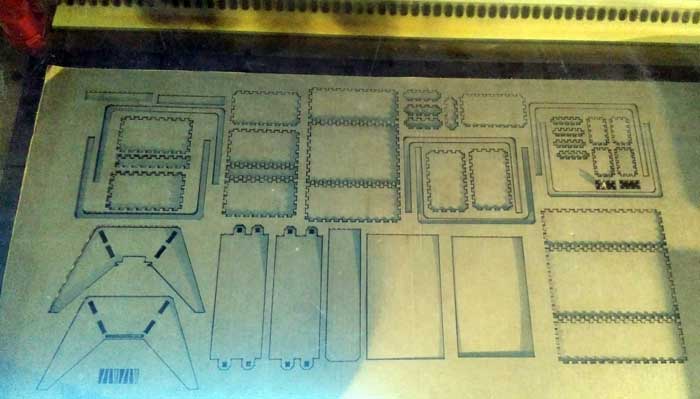
Once every component has been Made2D on the top view window, we are ready to go for laser cutting. A good tip is to work with different color strokes that is understood by the laser, as the "strategy" to follow. In my case, the black strokes represent a component inside another component and should be laser cut first, to avoid focal problem if we were doing the other way around.
STEPS FOLLOWED WITH RHINO: Import Box made on Inkscape / create top view projection of each component / create two layers (1 black for internal cutting and red for external cutting) / Nest the components to win some space / select print / Trotec Join Control driver / set material properties / Material: Cardboard / Thickness: 1,8mm / Power: 100% / Speed: 3% / Hz: 1000 / Ready
To win some space on nesting, I've discovered a browser-based vector nesting tool called SVGNest . It can be downloaded from Github
Using Acrylic
The idea was to "Box make" the aquarium and laser cut it with Acrylic.
To start with, I draw a small circle and test different Power / Speed / Hz settings configuration. When laser cut, Acrylic smells realy bad and can cause nausea. So a good tip is to wait for several minutes after the cutting in order to correctly evacuate the smoke before opening the machine.
 Set material properties / Material: Acrylic/ Thickness: 3mm.

        Test 1: Power: 100% / Speed: 3% / Hz: 1000 > Did not cut properly / need to run the laser 3 times

        Test 2: Power: 100% / Speed: 1% / Hz: 1000 > Seems OK

        Test 3: Power: 100% / Speed: 0.5% > The acrylic melt and some flames get out of the laser

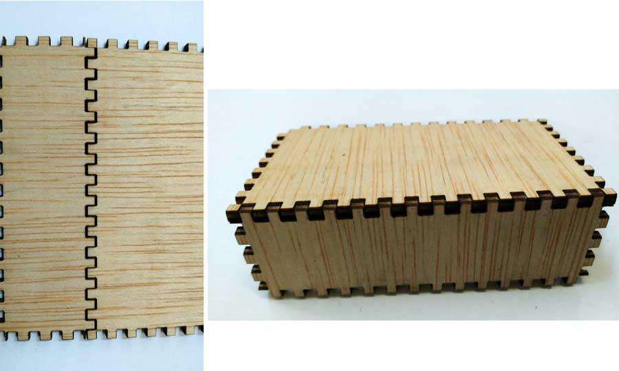
Using Plywood
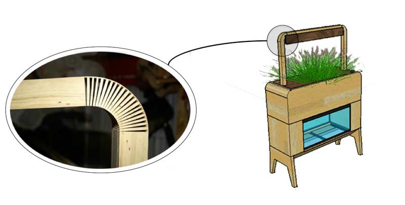
For the laser cut v2 aquaponic model, I wanted to use plywood and acrylic and turn each 90° sharp angle into a curve following my original model on Rhino. I think the kerf bending technique would help me working on that aspect. But first of all, let's find the set-up confirguration to "Box Make" plywwod
I will work with some 2.8 mm thickness plywood. To begin with let's find the right set up for kerf cutting and laser power / speed / Hz.
BOX MAKER
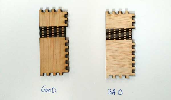
Tab Width = 2.5 mm Kerf value = 0.5mm > Not Good, to tight to assemble the joints Kerf value = 0.25mm > Good
JOIN CONTROL SET UP

                Material: Plywood
                Thickness: 2.8 mm
                Power: 80% / Speed: 1% / Hz: 20000
Kerf-bending
Looking a bit on Internet I found some nice research on Instructables proposing a .dxf file with ten different kerf bending patterns.

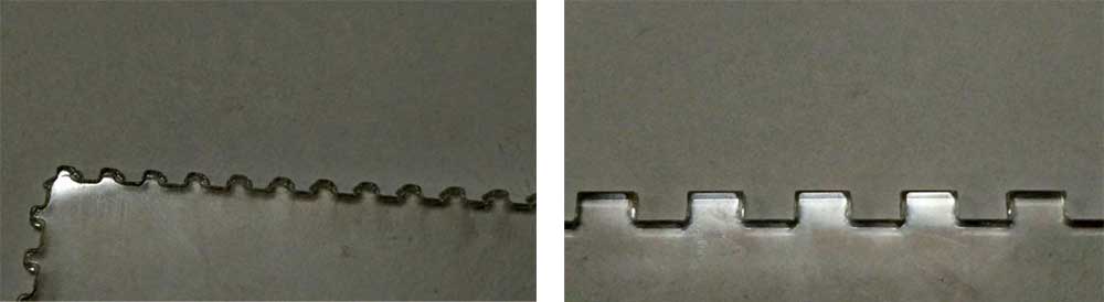
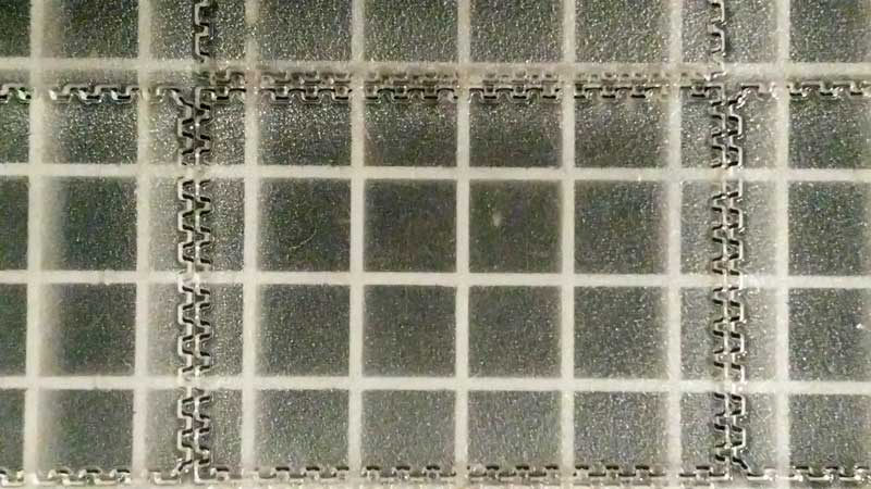
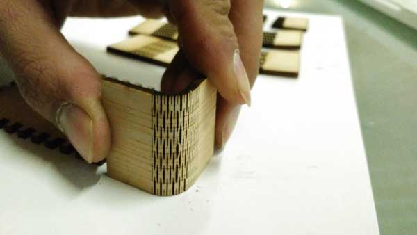
I give a first try with the Straight lattice, the most common lattice hinge and the most reliable. Lattice hinges rely on torsion of the material to bend and it's easy to see in this photo. The radius of the bend depends on the length of the cuts, the distance between them and the thickness of the material.
FIRST TEST
SET UP:
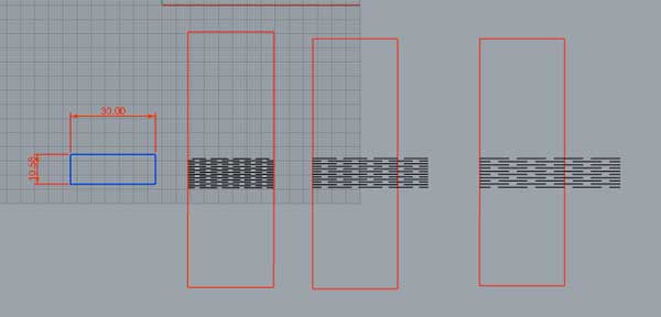
Material: Plywood Thickness: 2.8 mm External Cut (red line): Power= 100 / Speed = 1,5 / Hz = 20000 Internal Cut (blue line) Power= 80 / Speed = 1 / Hz = 10000 Kerf Bending surface: W= 10.59mm x L= 30 mm -Rectangle 1 / Kerf Bending delta = 0.68 mm -Rectangle 2 / Kerf Bending delta = 0.93 mm -Rectangle 3 / Kerf Bending delta = 1.13 mm
Then I tried them all doing a 90° angle and they all break down ...
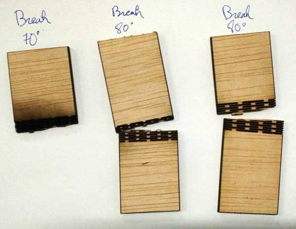
Key lessons learnt:

        1- One of the reason why it broke down is that kerf bending direction should never be in the same direction of the wood fiber direction but perpendicular... which was my case
        2- May be the power was too strong
        3- Kerf area was too small
SECOND TEST
SET UP

         Material: Plywood
         Thickness: 2.8 mm
         External Cut (red line): Power= 75 / Speed = 1 / Hz = 20000
         Internal Cut (blue line) Power= 90 / Speed = 1,5 / Hz = 10000
         Kerf Bending surface: W= 10.59mm  x L= 30 mm
         -Rectangle 1 / Kerf Bending delta = 0.68 mm
         -Rectangle 2 / Kerf Bending delta = 0.93 mm
         -Rectangle 3 / Kerf Bending delta = 1.13 mm

         Kerf Bending surface: W= 13.68mm  x L= 30 mm
         -Rectangle 4 / Kerf Bending delta = 0.68 mm
         -Rectangle 5 / Kerf Bending delta = 0.93 mm
         -Rectangle 6 / Kerf Bending delta = 1.13 mm


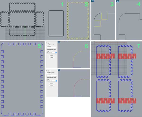
Once the right kerf bending set up configuration has been found I've been adapting the Box Maker and Kerf bending pattern together doing the following steps.
STEPS

         1) lk
         2) lk
         3) lk
         4) lk
         5) lk
         6) Mesuring the lenght of the side curve with "lenght" command > height of surface of the kerf bending area + other space (need to be explained).
         7) lk

If the time allow me, I will try to work on parametric kerf using Grasshoper.
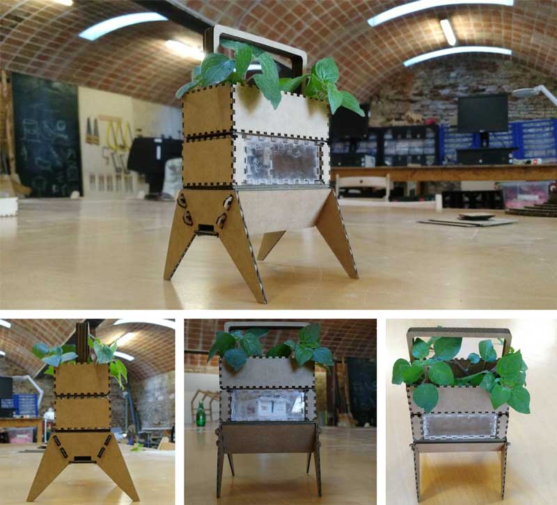
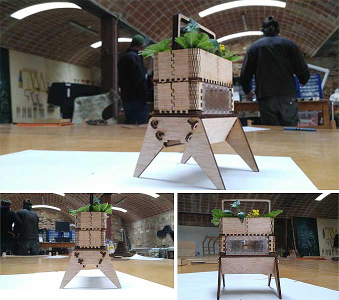
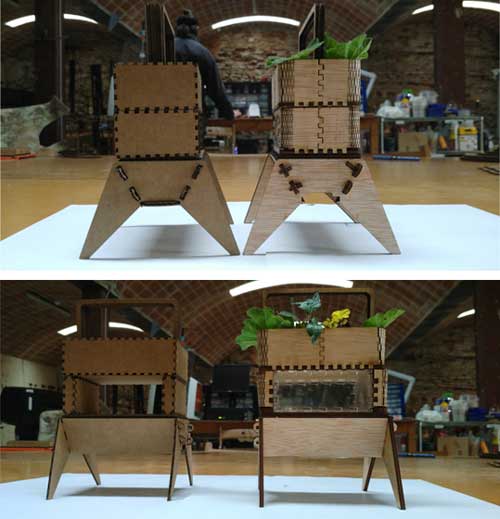
Aquaponic v2: Joint Structure + Kerf-Bending + Plywood + Acrylic
Now it's time to apply all the previous techniques learnt this week for a v2 model
Vinyl Cutting
Coming soon
Download
You access and download all the files generated during this week from my google drive:
Conclusion
During this week I've discovered the magic of laser cutting and engraving using different materials to turn the indoor aquaponic garden 3D model done on Rhino into a small sized kit. One of the key outcome of this week is to start laser cutting very small pieces first to find out the right "Power/Speed/Hz" presets associated to the material used. When it comes to Kerf bending, it's an iterative process: "apply different set-up on various samples".