Week #2 COMPUTER-AIDED DESIGN
Model (draw, render, animate, simulate, ...) a possible final project, and post it on your class page with original 2D and 3D files.
Assignment
Softwares used
- Photoshop
- Inkscape
- OpenSCAD
- Sketchup
- Rhino
2D software: Photoshop / Inkscape
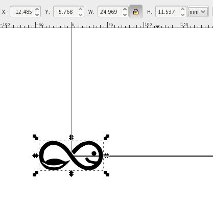
Converting Aquapioneers' Bitmap logo into Vector
I decided to work with the Aquapioneers' logo I recently drafted. I first open it with Photoshop and convert it in black and white and saved it as .jpg to get a bitmap image

To convert this bitmap into a vector image, I've used Inkscape and followed these steps
Image selected / path trace image thresthold (the lower the value is the more white the higher the value is the darker / we hit ok and we close the window

Then to prepare the vector for OpenScad we must do some tricks. As OpenScad has a problem with curves, we must convert all the curves to corner points.
	         Select the shape, extensions / modify path / flatten beziers (The small the number, the closes aproximation, the more lines, the bigger the file will be: We have a compromise with this. We chose now 0.1 click ok and close the window;
             Now file save as: we choose autocad .dxf (unit: mm, uncheck LWPOLYline)
3D software: OpenSCAD / Sketchup / Rhino
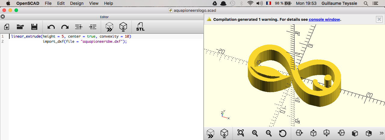
OpenSCAD
OpenSCAD is a free CAD software that will be usefull when it comes to 3D printing. To get started with Open OPenScad, open a new file. A code window will appear on the left side and a 3d window on the right side. To get started I've open the Help / Documentation and go to point 4 “Using 2Dsubsytem” / click point 1.4 / import dxf. It is goood the remember that values in OPenScad are in millimeters and you nedd to save it on the same folder as the dxf (always same folder) otherwise the compilation will not work.
	           <pre linear_extrude(height = 5, center = true, convexity = 10)
                import_dxf(file = "aquapioneers.dxf";>
Then go to design and click on render. If we want to change the size of the model, we can go back to inkscape and change it there and save it and go back to OPenScad and render again
Now let's add a new object (a polygon) and place it underneath Aquapioneers' log. For that follow the previous process with a new file on Inkscape and open it in OpenSCAD. In the help we search for translate, on the point 3. An then copy the following line between the two lines
<pre translate(v = [x, y, z]) { ... } >
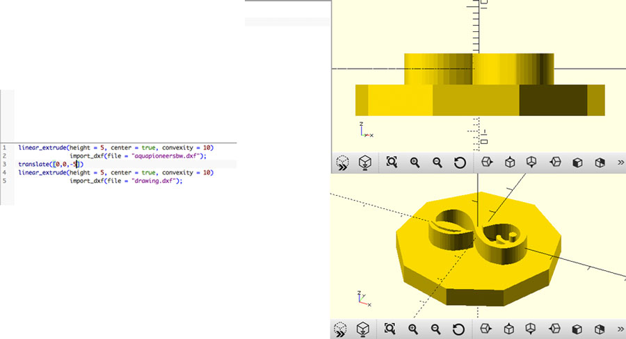
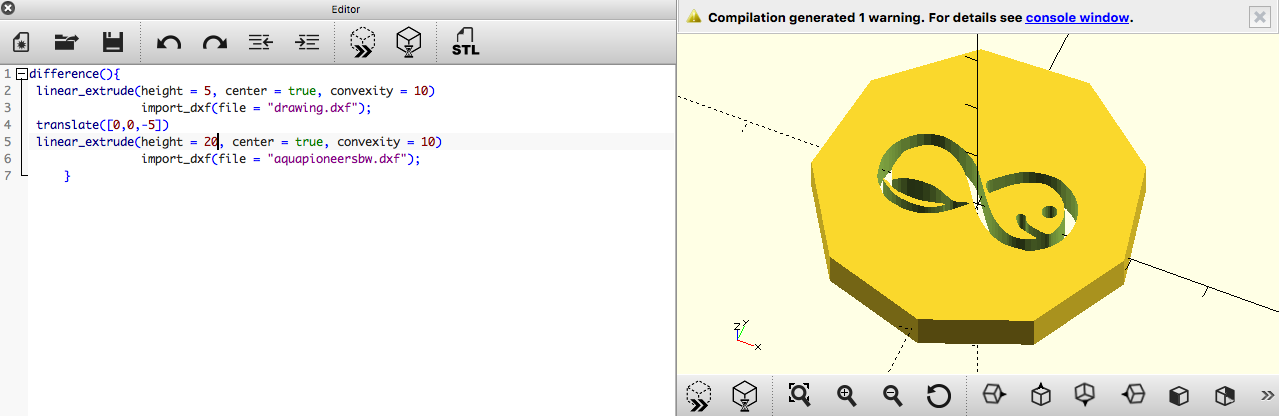
Now let's work on difference between two objects. For that make sure the polygon goes throw the logo shape
	           <pre difference(){
               linear_extrude(height = 5, center = true, convexity = 10)
               import_dxf(file = "aquapioneers.dxf");
               translate([0, 0, -1])
               linear_extrude(height = 10, center = true, convexity = 10)
                import_dxf(file = "polygon.dxf");
                }  >
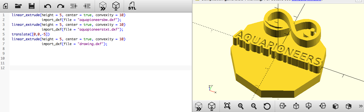
Now let's do it with fonts.
- Type something
- Path object to path (convert it to path)
- Ungruop the object (object ungroup)
- Path combine or ctrl k
- Ctrl d or edit duplicate
- Path dynamic offset
- Drag the handle and make it bigger the size
- Object filll and stroke and change the stroke
- Select the stroke path
- Object to path and with the secondary arrow we can edit the bezier points and hadlers (if the path is not closed, select the path and click on the fourth small icon under second icon menu to join selected path)
- Move one up and the other down with the layer section
- Click ctrl - or path difference with both paths selected
- Extension modify path flatten beziers 0.1
- Save as .dxf

And here is the result with OpenSCAD
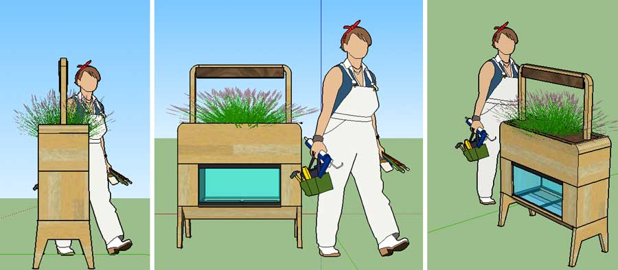
Using Sketchup to quickly draft my original idea
As I was a bit familiar with Sketchup and wanted to give a first shot to 3D model the indoor aquaponics garden I have in mind. It enabled me to learn how to create different shapes, assemble them into components, texturize them / rotate them / etc
A nice feature with Sketchup is that you have access to one of the world's largest site for downloading 3D Models to fuel your creative pursuit: 3D Warehouse . So to place the aquapioneers indoor garden into a housing context, I've downloaded a kitchen model.
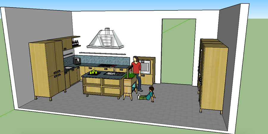
Next step will be rendering ! After some bibliography, I decided to try with LightUp a SketchUp renderer plugin that uses object-based. rendering. This means you get results instantly inside the SketchUp window. The speed of LightUp makes it adapted for quick rendering. You can tweak and iterate your models and immediately see results without waiting around for minutes. You can move the camera around your model and watch everything render in real time. I've included some snapshots of the rendering in the flick'r gallery below

Get introduced to Rhino
I get introduced to Rhino for the first time this week so I started to get familiar with it by following a nice tutorial from our local guru. We worked on a coffe cup in order to learn the basic functions.
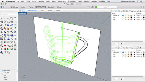
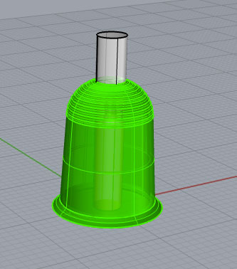
Knowing the basic now, I have chosen to work on a pot, a small structure, that will provide support to the plants and their roots in the aquaponics grow bed in order to help them grow healthy..
First action has been to import a bitmap picture that wil help me design the general form of the pot.
Command: "picture frame" helped me to import the bitmap picture frame
Command: "polyline" helped me to trace a line that follow the external shape of the picture.
Command: "revolve” helped me to create a surface by revolving the profile curve that defines the surface shape around the Z axis
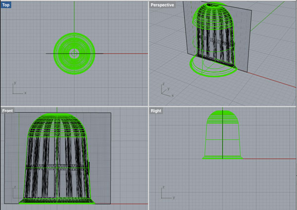
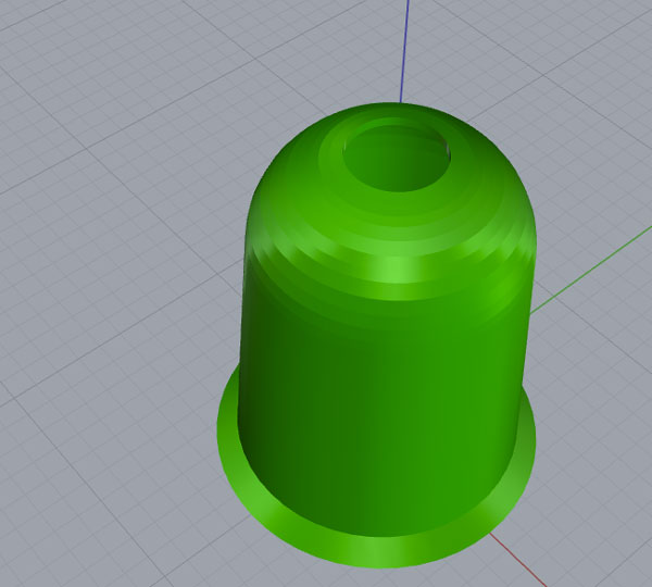
Command: "render" helped to render the model using the current renderer producing a color image in a separate display window.
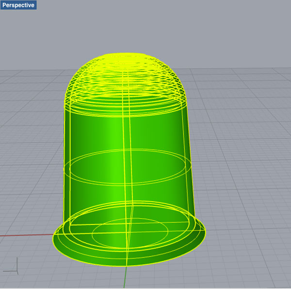
Command: "BooleanDifference" helped me to trim the shared areas of pot & cylender polysurfaces to open the base and top part of the pot
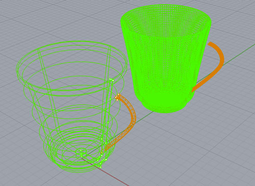
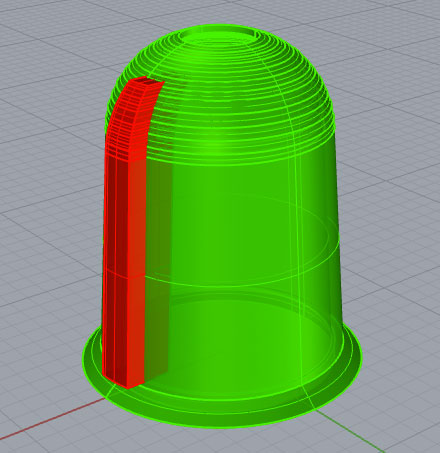
Now its time to extract some materials to enable the plants roots to get in contact with the grow bed.
Command: "polyline" helped me to trace a line that follow the external shape of the picture.
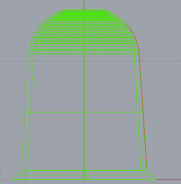
Command: "Revolve" (angle=15°) helped me to generate a required polysurface to be extracted later on.
Command: "Cap" helped me to join the hole edge of this opened surface into a single solid.
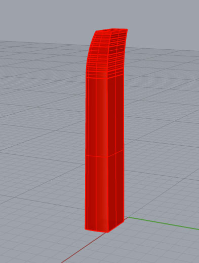
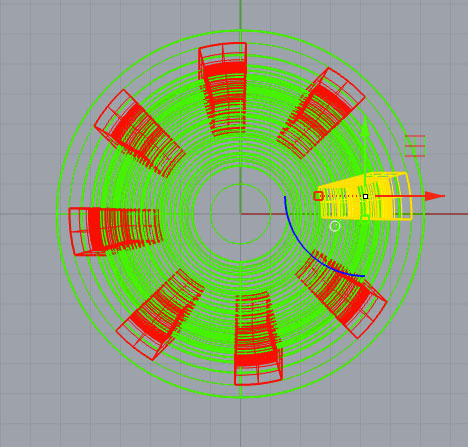
Command: "ArrayCrv" helped me to duplicate the red solid 8 times along a circle curve.
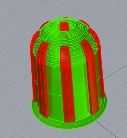
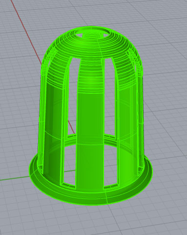
Command: "BooleanDifference" helped me trim the shared areas of selected red and green polysurfaces
Knowing the basic now, I have chosen to work on a pot, a small structure, that will provide support to the plants and their roots in the aquaponics grow bed in order to help them grow healthy..
First action has been to import a bitmap picture that wil help me design the general form of the pot.
Command: "picture frame" helped me to import the bitmap picture frame
Command: "polyline" helped me to trace a line that follow the external shape of the picture.
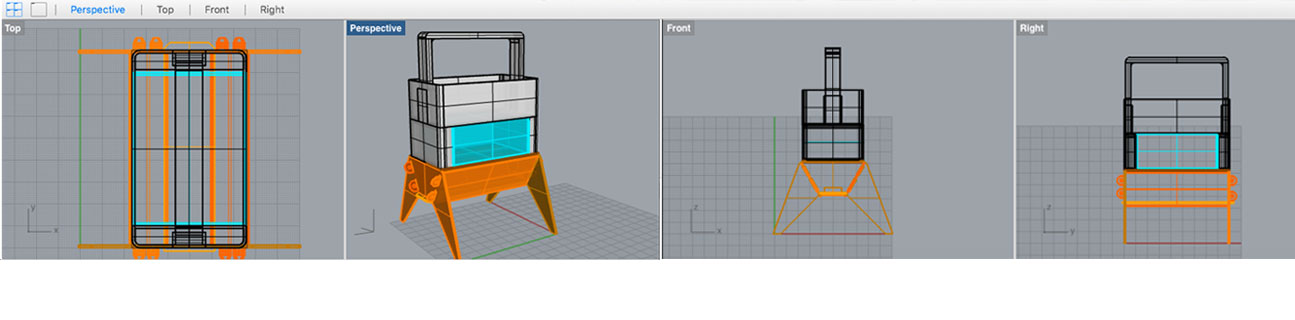
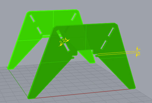
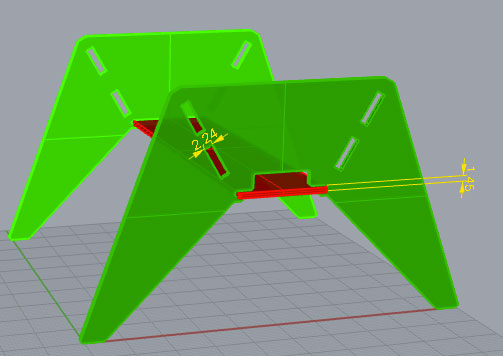
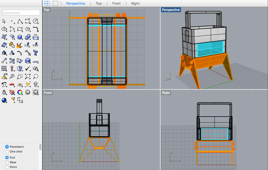
Modelling the original idea with Rhino to prepare next week "laser cutting"
As next week, we will work on laser cutting I wanted to model with precision my first design idea, so that I would be able to laser cut it next week in order to have a first look and feel.
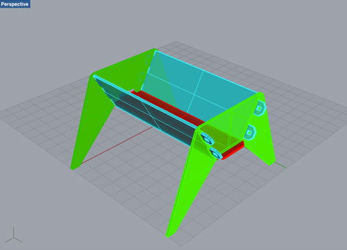
I started by modelling the table on which the aquaponics system will be based on. To work on something more original, I get inspired by the Colorado opensource beehives design project.
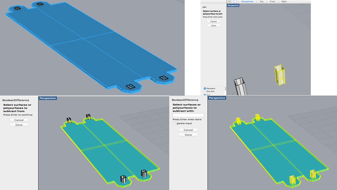
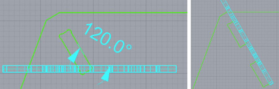
Command used: "Polyline", "Cap" (to turn closed polysurface into a solid), "ExtrudeCrV", "Join", BooleanDiff", etc
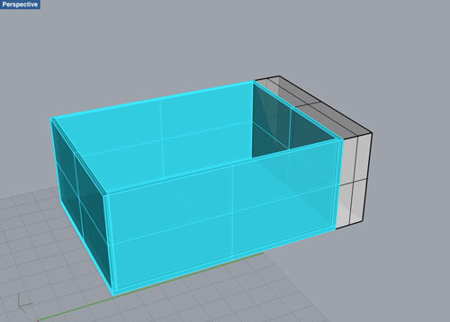
Then working on the design of the aquarium, the grow bed and the lighting system
Command used: "Shell" command creates a hollowed out shell from a solid. Shell only operates on simple, solid, manifold polysurfaces. These surfaces are removed and the remainder is offset inward, using the outer parts of the removed surfaces to join the inner and outer parts. Nice tutorial on youtube
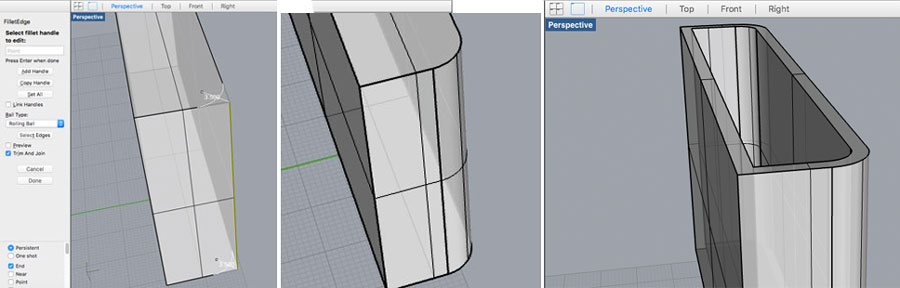
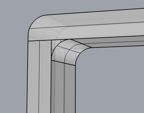
Commands used: (1)"Filet Edge" creates a tangent surface between polysurface edges with varying radius values then trims and joins the original faces to the fillet surfaces. Followed by a "Shell".
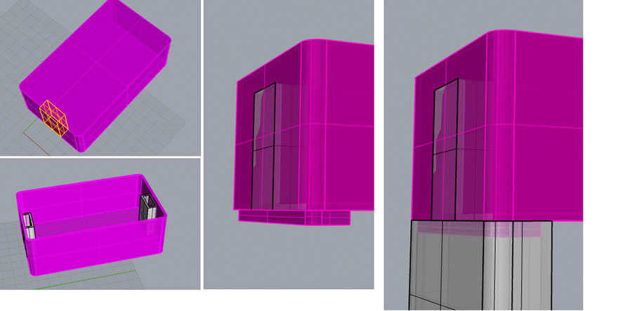
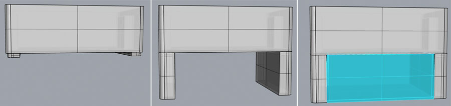
Command used: (1)"The BooleanUnion" command trims the shared areas of selected polysurfaces or surfaces and creates a single polysurface from the unshared areas (2) Followed by a "Filet Edge"
Now that we have all the major modules for the aquaponics system, we can visualize a step by step approach to build it.
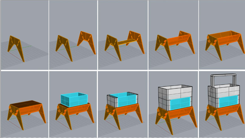
I've included below the 3D Model. It can be rotated and zoomed with the mouse/trackpad.
Download
You access and download all the files generated during this week from my google drive:
Conclusion
During this week I got to use many different 2D and 3D softwares. As I was almost new to any 2D and 3D softwares and curious to try different ones, I decided to use each software for a different purpose. 2D software helped me to work on the Aquapioneers logo. 3D software Sketchup helped me to quickly sketch the first design I had in mind for the indoor aquaponics garden. Using its warehouse and rendering plugin, it also help to vizualize the aquaponic system into a housing / kitchen context. 3D software Rhino helped me to design a specific aquaponic component, a pot that could be later on 3D printed to provide support for the plants and also the first design I had in mind for the indoor aquaponics system. I would have loved to try SolidWorks as an alternative for Rhino, but didn't have time this week. Let's do it next one then !